EP1424812A2 - Eine drahtlose lokale Anschlusseinheit zum Verbinden in das Internet - Google Patents
Eine drahtlose lokale Anschlusseinheit zum Verbinden in das Internet Download PDFInfo
- Publication number
- EP1424812A2 EP1424812A2 EP03022216A EP03022216A EP1424812A2 EP 1424812 A2 EP1424812 A2 EP 1424812A2 EP 03022216 A EP03022216 A EP 03022216A EP 03022216 A EP03022216 A EP 03022216A EP 1424812 A2 EP1424812 A2 EP 1424812A2
- Authority
- EP
- European Patent Office
- Prior art keywords
- data
- isp
- wireless lan
- current position
- spot
- Prior art date
- Legal status (The legal status is an assumption and is not a legal conclusion. Google has not performed a legal analysis and makes no representation as to the accuracy of the status listed.)
- Granted
Links
Images


Classifications
-
- H—ELECTRICITY
- H04—ELECTRIC COMMUNICATION TECHNIQUE
- H04W—WIRELESS COMMUNICATION NETWORKS
- H04W48/00—Access restriction; Network selection; Access point selection
- H04W48/18—Selecting a network or a communication service
-
- H—ELECTRICITY
- H04—ELECTRIC COMMUNICATION TECHNIQUE
- H04L—TRANSMISSION OF DIGITAL INFORMATION, e.g. TELEGRAPHIC COMMUNICATION
- H04L67/00—Network arrangements or protocols for supporting network services or applications
- H04L67/50—Network services
- H04L67/52—Network services specially adapted for the location of the user terminal
-
- H—ELECTRICITY
- H04—ELECTRIC COMMUNICATION TECHNIQUE
- H04L—TRANSMISSION OF DIGITAL INFORMATION, e.g. TELEGRAPHIC COMMUNICATION
- H04L67/00—Network arrangements or protocols for supporting network services or applications
- H04L67/50—Network services
- H04L67/55—Push-based network services
-
- H—ELECTRICITY
- H04—ELECTRIC COMMUNICATION TECHNIQUE
- H04L—TRANSMISSION OF DIGITAL INFORMATION, e.g. TELEGRAPHIC COMMUNICATION
- H04L69/00—Network arrangements, protocols or services independent of the application payload and not provided for in the other groups of this subclass
- H04L69/30—Definitions, standards or architectural aspects of layered protocol stacks
- H04L69/32—Architecture of open systems interconnection [OSI] 7-layer type protocol stacks, e.g. the interfaces between the data link level and the physical level
- H04L69/322—Intralayer communication protocols among peer entities or protocol data unit [PDU] definitions
- H04L69/329—Intralayer communication protocols among peer entities or protocol data unit [PDU] definitions in the application layer [OSI layer 7]
-
- H—ELECTRICITY
- H04—ELECTRIC COMMUNICATION TECHNIQUE
- H04W—WIRELESS COMMUNICATION NETWORKS
- H04W4/00—Services specially adapted for wireless communication networks; Facilities therefor
- H04W4/02—Services making use of location information
Definitions
- This invention relates to an electronic apparatus having a wireless LAN connecting unit.
- the electronic apparatus is, for example, a computer apparatus, a PDA (Personal Digital Assistant), or the like.
- the electronic apparatus will also be called a client apparatus which makes use of functions and data provided by a server computer.
- a wireless LAN (Local Area Network) is foruse in connecting a computer apparatus (for example, a personal computer) to the Internet via wireless connection.
- the wireless LAN is established between the computer apparatus and a communication apparatus connected to the Internet by providing the computer apparatus with a wireless LAN connecting unit (for example, a wireless LAN adapter such as a wireless LAN card) and providing the communication apparatus with an access point.
- a wireless LAN connecting unit for example, a wireless LAN adapter such as a wireless LAN card
- a space having the access point and providing a wireless Internet connection service hosted by an ISP (Internet Service Provider) to an unspecified number of general public users is generally called a hot spot.
- ISP Internet Service Provider
- the above-mentioned space providing the wireless Internet connection service may be called a providing spot.
- the computer apparatus having the wireless LAN connecting unit can not automatically select a wireless LAN communication mode (determined by a radio frequency channel and a transmit power level) in conformity with a wireless specification and radio laws and regulations of each individual country. Therefore, in case where the wireless LAN connecting unit equipped in the computer apparatus does not match the wireless specification and the radio laws and regulations of a country where a user currently stays or lives, the wireless LAN connecting unit equipped in the computer apparatus is replaced by another wireless LAN connecting unit which matches the wireless specification and the radio laws and regulations of the country.
- the computer apparatus having a wireless LAN connecting unit is used in a plurality of providing spots (hot spots) hosted by a plurality of ISPs different from one another.
- the computer apparatus when the computer apparatus is brought to each providing spot, it is required for a user to ask a manager of each providing spot about an ISP hosting the providing spot and setup data and to manually change the setup data such as authentication information.
- JP 2002-185476 A (corresponding to EP 1207654 A2) (which will be referred to as Reference 1) discloses the technique for use in frequency coordination between two different wireless network protocols, such as the IEEE 802.11 protocol and the Bluetooth protocol.
- the coordination is accomplished by the use of a first radio transceiver operating in accordance with a first communication protocol (which may be the 802 .11 protocol) and using a frequency band (which may be 2.4 GHz), a base station connected to a wired network and operating in accordance with the first communication protocol, a second radio transceiver operating in accordance with a second communication protocol (which may be the Bluetooth protocol) and using the above-mentioned frequency band, and a coordinator associated with the base station for, in turn, activating the first radio transceiver, deactivating the first radio transceiver, activating the second radio transceiver, and deactivating the second radio transceiver.
- a first communication protocol which may be the 802 .11 protocol
- a frequency band which may be 2.4 GHz
- a base station connected to a wired network and operating in accordance with the first communication protocol
- a second radio transceiver operating in accordance with a second communication protocol (which may be the Bluetooth protocol) and using the
- Japanese Unexamined Patent Publication No. JP 07-336294 A (corresponding to EP 0684707 A1) (which will be referred to as Reference 2) describes that national regulations of each country set a maximum limit on the amount of effective isotropic radiated power (EIRP) which may be emitted from a particular type of antenna being used for a particular application.
- EIRP effective isotropic radiated power
- Reference 2 discloses a cellular radio base station arrangement capable of controlling transmit power so that the transmit power does not exceed the maximum limit of EIRP defined by the national regulations.
- Japanese Unexamined Patent Publication No. JP 2001-223712 A (which will be referred to as Reference 3) discloses an information retrieval service system capable of reliably providing a wireless terminal user of a wide-area wireless network with area information regarding an area in which the user is present and guide information regarding stores, shops and so on located in the neighborhood.
- Japanese Unexamined Patent Publication No. JP 2002-152276 A (which will be referred to as Reference 4) discloses a method which enables a personal terminal to be used in an Internet connection environment of a public spot so as to use the same ISP (Internet Service Provider) at home and at the public spot.
- ISP Internet Service Provider
- the computer apparatus may not be connected to the wireless LAN due to the difference in standard or radio laws and regulations from country to country. If the wireless LAN connecting unit itself can not be used in a destination country, another wireless LAN connecting unit having a specification adapted to the destination country must be purchased or borrowed there.
- a current position data acquiring unit for acquiring current position data representative of a current position of the computer apparatus (or the client apparatus) and which is capable of identifying a current-location area (country or state) from the current position data and automatically changing a wireless LAN communication mode (determined by a radio frequency channel and a transmit power level) in conformity with a wireless specification and radio laws and regulations of each area.
- a computer apparatus comprising:
- a computer apparatus comprising:
- a computer apparatus comprising:
- a client apparatus comprising:
- a client apparatus comprising:
- a client apparatus comprising:
- References 1, 2, 3, and 4 discloses a current position data output unit for producing current position data representative of a current position of a computer apparatus (or a client apparatus), a position data table, an ISP agreement data table, a specific area data output unit responsive to the current position data for producing specific area data representative of a specific area including the currentposition, an ISP data output unit responsive to the current position data for producing, as specific ISP data, data related to an ISP of a providing spot (hot spot) where the computer apparatus (or the client apparatus) is brought, and an enable signal output unit.
- a wireless LAN connecting unit automatically selects, as a selected communication mode, one of a plurality of wireless LAN communication modes which corresponds to the specific area data and carries out Internet connection via a wireless LAN in the selected communication mode.
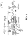
- a computer apparatus 10 is, for example, a personal computer and comprises a wireless LAN connecting unit 11 and an enabling arrangement 12.
- the wireless LAN connecting unit 11 carries out connection with the Internet 14 via a wireless LAN (Local Area Network) 13.
- the wireless LAN connecting unit 11 is a wireless LAN adapter such as a wireless LAN card.
- the wireless LAN 13 is established between the computer apparatus 10 and a communication apparatus 16 connected to the Internet 14 by providing the computer apparatus 10 with the wireless LAN connecting unit 11 and providing the communication apparatus 16 with an access point 15.
- a hot spot (or providing spot) HP#1 is a space having the access point 15 and providing a wireless Internet connection service hosted by an ISP (internet Service Provider) to an unspecified number of general public users.
- Another hot spot (or providing spot) HP#2 is located at a different position and hosted by a different ISP.
- the enabling arrangement 12 enables the wireless LAN connecting unit 11 to carry out Internet connection via the wireless LAN 13 in either of the first and the second providing spots HP#1 and HP#2 located at first and second positions different from each other and hosted by first and second ISPs different from each other.
- the enabling arrangement 12 comprises a current position data output unit 17, a position data table 18, an ISP agreement data table 19, an area data and ISP data output unit 20, and an enable signal output unit 21.
- the current position data output unit 17 produces current position data representative of a current position of the computer apparatus 10.
- the current position data output unit 17 is, for example, a GPS (Global Positioning System) receiver responsive to a GPS signal for producing current position data representative of a current position of the computer apparatus 10.
- the current position data output unit 17 may be a gyroscope for producing current position data representative of a current position of the computer apparatus 10.
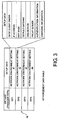
- the position data table 18 memorizes, in correspondence to first and second spot data representative of the first and the second providing spots HP#1 and HP#2 (assumed to be Hamburger Shop Sumida and Coffee Shop New York), first and second spot position data representative of the first and the second positions (north latitude N and east longitude E of Hamburger Shop Sumida and north latitude N and west longitude W of Coffee Shop New York) , first and second area data (country data in Fig. 2) representative of first and second areas (country or state; Japan and U.S.A. in Fig.
- the position data table 18 memorizes spot position data, country data, and ISP data in correspondence to other providing spots (Coffee Shop Shibuya, Hamburger Shop Daikanyama, and Hotel Akasaka).
- the ISP agreement data table 19 memorizes, in correspondence to the first and the second ISP data representative of the first and the second ISPs (ISP1 and ISP4), first and second agreement data (setup data) representative of agreements made between a user of the computer apparatus 10 and the first and the second ISPs (ISP1 and ISP4).
- the ISP agreement data table 19 memorizes, in correspondence to the first and the second ISP data representative of other ISPs (ISP2 and ISP3), agreement data (setup data) made between the user of the computer apparatus 10 and other ISPs (ISP2 and ISP3).
- the ISP agreement data table 19 in Fig. 3 memorizes only the first and the second agreement data (setup data) corresponding to the first and the second ISP data representative of the first and the second ISPs (ISP1 and ISP4). Furthermore, the position data table 18 in Fig.
- the second spot data representative of the first and the second providing spots HP#1 and HP#2 (Hamburger Shop Sumida and Coffee Shop New York)
- the first and the second spot position data representative of the first and the second positions (north latitude N and east longitude E of Hamburger Shop Sumida and north latitude N and west longitude W of Coffee Shop New York)
- the first and the second area data representative of the first and the second areas (Japan and U.S.A.) including the first and the second providing spots HP#1 and HP#2
- the first and the second ISP data representative of the first and the second ISPs (ISP1 and ISP4) hosting the first and the second providing spots HP#1 and HP#2.
- the area data and ISP data output unit 20 identifies, as specific spot data, one of the first and the second spot data which corresponds to one of the first and the second spot position data which coincides with the current position data.
- the area data and ISP data output unit 20 produces, as specific area data (specific country data) 22, one of the first and the second area data (first and second country data) which corresponds to the specific spot data and produces, as specific ISP data 23, one of the first and the second ISP data which corresponds to the specific spot data.
- the enable signal output unit 21 produces an enable signal ENA in case where the ISP agreement data table 19 memorizes one of the first and the second agreement data in correspondence to one of the first and the second ISP data which coincides with the specific ISP data 23.
- the wireless LAN connecting unit 11 is preliminarily given a plurality of wireless LAN communication modes 24 corresponding to a plurality of area data (a plurality of country data).
- the wireless LAN connecting unit 11 In response to the enable signal ENA and the specific area data 22, the wireless LAN connecting unit 11 automatically sets, as a selected communication mode, one of the wireless LAN communication modes 24 which corresponds to the specific area data 22 and carries out Internet connection via the wireless LAN 13 in the selected communication mode.
- each of the wireless LAN communication modes 24 corresponding to the area data is determined by a radio frequency channel and a transmit power level used in an area (country) represented by area data (country data) corresponding thereto.
- the wireless LAN connecting unit 12 carries out Internet connection via the wireless LAN 13 by the use of the radio frequency channel and the transmit power level which determine the selected communication mode.
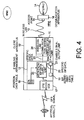
- a client apparatus 10' is, for example, a personal computer or a PDA (Personal Digital Assistant) and comprises similar parts designated by like reference numerals.
- PDA Personal Digital Assistant
- the client apparatus 10' illustrated in Fig. 4 has a GPS (Global Positioning System) receiver 17' as a current position data output unit.
- the GPS receiver 17' receives a GPS signal from an artificial satellite and produces current position data representative of a current position of the client apparatus 10'.
- the GPS receiver 17' may be replaced by a gyroscope for producing current position data representative of a current position of the client apparatus 10'.
- the client apparatus 10' in Fig. 4 is similar to the computer apparatus 10 in Fig. 1.
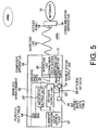
- a computer apparatus 30 is, for example, a personal computer and is similar to the computer apparatus in Fig. 1 except the following.
- the position data table 18 in Fig. 1 is replaced by a position data table 18'.
- the area data and ISP data output unit 20 in Fig. 1 is replaced by an area data output unit 20' and an ISP data output unit 20".
- the position data table 18' memorizes, in correspondence to the first and the second spot data representative of the first and the second providing spots HP#1 and HP#2 (assumed tobe Hamburger Shop Sumida and Coffee Shop New York), first and second spot position data representative of the first and the second positions (north latitude N and east longitude E of Hamburger Shop Sumida and north latitude N and west longitude W of Coffee Shop New York), and the first and the second ISP data (provider data) representative of the first and the second ISPs (ISP1 and ISP4 in Fig. 2) hosting the first and the second providing spots HP#1 and HP#2. It is noted here that the position data table 18' in Fig.
- the position data table 18' memorizes the spot position data and the ISP data in correspondence to other providing spots (Coffee Shop Shibuya, Hamburger Shop Daikanyama, and Hotel Akasaka). It is noted here that the position data table 18' does not memorize the country data in the position data table 18 illustrated in Fig. 2.
- the user of the computer apparatus 30 has an agreement only with the first and the second ISPs (ISP1 and ISP4) and that the ISP agreement data table 19 (Fig. 3) memorizes only the first and the second agreement data (setup data) corresponding to the first and the second ISP data representative of the first and the second ISPs (ISP1 and ISP4). Furthermore, the position data table is' in Fig.
- the 6 memorizes, in correspondence to the first and the second spot data representative of the first and the second providing spots HP#1 and HP#2 (Hamburger Shop Sumida and Coffee Shop New York), the first and the second spot position data representative of the first and the second positions (north latitude N and east longitude E of Hamburger Shop Sumida and north latitude N and west longitude W of Coffee Shop New York), and the first and the second ISP data representative of the first and the second ISPs (ISP1 and ISP4) hosting the first and the second providing spots HP#1 and HP#2.
- the area data output unit 20' is supplied with the current position data from the current position data output unit 17 and produces the specific area data (specific country data) 22 representative of the specific area (specific country) including the current position.
- the ISP data output unit 20" identifies, as the specific spot data, one of the first and the second spot data which corresponds to one of the first and the second spot position data which coincides with the current position data.
- the ISP data output unit 20" produces, as specific ISP data 23, one of the first and the second ISP data which corresponds to the specific spot data.
- the enable signal output unit 21 produces an enable signal ENA in case where the ISP agreement data table 19 memorizes one of the first and the second agreement data in correspondence to one of the first and the second ISP data which coincides with the specific ISP data 23.
- the wireless LAN connecting unit 11 Supplied with the enable signal ENA from the enable signal output unit 21 and the specific area data 22 from the area data output unit 20', the wireless LAN connecting unit 11 automatically sets, as a selected communication mode, one of the wireless LAN communication modes 24 which corresponds to the specific area data 22 and carries out Internet connection via the wireless LAN 13 in the selected communication mode.
- a client apparatus 30' is, for example, a personal computer or a PDA (Personal Digital Assistant) and comprises similar parts designated by like reference numerals.
- PDA Personal Digital Assistant
- the client apparatus 30' illustrated in Fig. 7 has a GPS (Global Positioning System) receiver 17' as a current position data output unit.
- the GPS receiver 17' receives a GPS signal from an artificial satellite and produces current position data representative of a current position of the client apparatus 30'.
- the GPS receiver 17' maybe replaced by a gyroscope for producing current position data representative of a current position of the client apparatus 30'.
- the client apparatus 30' in Fig. 7 is similar to the computer apparatus 30 in Fig. 5.
- a server 50 connected to the Internet 14 is provided with a position data table 51 similar to the position data table 18 in Fig. 2 which memorizes the correspondence among the spot position data, the country data, the spot data, and the ISP data (provider data). If the position data table 51 is modified and updated, for example, by addition of a new providing spot (hot spot) , the server 50 informs the update to the computer apparatus 10 (Fig. 1) or the client apparatus 10'.
- the computer apparatus 10 (Fig. 1) or the client apparatus 10' (Fig. 4) informs the user of the update.
- the computer apparatus 10 (Fig. 1) or the client apparatus 10' (Fig. 4) accesses to the server 50 via the Internet 14 and downloads the data of the position data table 51 from the server 50 to the computer apparatus 10 or the client apparatus 10'.
- the area data of the current position are changed in accordance with the current position data received by the GPS receiver (or produced by the gyroscope) and informed to the wireless LAN connecting unit.
- the providing spot (hot spot) including the current position is identified and the wireless LAN connecting unit is automatically adapted to the ISP different at each providing spot (hot spot).
- a setting which matches the radio laws and regulations and the wireless specification of the area including the current position is extracted in accordance with the area data.
- the setting thus extracted is incorporated into the wireless LAN connecting unit so that the wireless LAN connecting unit canbe immediately used at a wireless LAN access point visited by the user in order to repeatedly perform wireless LAN connection.
- the user can immediately use the computer apparatus (or the client apparatus) to access to the wireless LAN without being conscious of the movement among the providing spots (hot spots) and without changing, by himself, the network setting, agreement setting, and charging information of a client system.
- a computer apparatus or a client apparatus having a wireless LAN connecting unit, which comprises a current position data acquiring unit for acquiring current position data representative of a current position of the computer apparatus (or the client apparatus), and which is capable of identifying a current-location area (country or state) from the current position data and automatically changing a setting of a wireless LAN communication mode (determined by a radio frequency channel and a transmit power level) in conformity with a wireless specification and radio laws and regulations of each area.
- a computer apparatus or a client apparatus having a wireless LAN connecting unit, which comprises a current position data acquiring unit for acquiring current position data representative of a current position of the computer apparatus (or the client apparatus), and which is capable of identifying a current-location providing spot (hot spot) from the current position data and automatically adapting the wireless LAN connecting unit to an ISP different at each providing spot (hot spot) without the need of manually changing ISP agreement data.
Landscapes
- Engineering & Computer Science (AREA)
- Computer Networks & Wireless Communication (AREA)
- Signal Processing (AREA)
- Computer Security & Cryptography (AREA)
- Mobile Radio Communication Systems (AREA)
- Information Transfer Between Computers (AREA)
- Small-Scale Networks (AREA)
Applications Claiming Priority (2)
| Application Number | Priority Date | Filing Date | Title |
|---|---|---|---|
| JP2002341783A JP4355483B2 (ja) | 2002-11-26 | 2002-11-26 | コンピュータ装置 |
| JP2002341783 | 2002-11-26 |
Publications (3)
| Publication Number | Publication Date |
|---|---|
| EP1424812A2 true EP1424812A2 (de) | 2004-06-02 |
| EP1424812A3 EP1424812A3 (de) | 2006-12-20 |
| EP1424812B1 EP1424812B1 (de) | 2018-06-13 |
Family
ID=32290399
Family Applications (1)
| Application Number | Title | Priority Date | Filing Date |
|---|---|---|---|
| EP03022216.0A Expired - Lifetime EP1424812B1 (de) | 2002-11-26 | 2003-09-30 | Eine drahtlose lokale anschlusseinheit zum verbinden in das internet |
Country Status (6)
| Country | Link |
|---|---|
| US (1) | US7218627B2 (de) |
| EP (1) | EP1424812B1 (de) |
| JP (1) | JP4355483B2 (de) |
| AU (1) | AU2003248469B2 (de) |
| CA (1) | CA2443651A1 (de) |
| TW (1) | TWI237967B (de) |
Families Citing this family (1)
| Publication number | Priority date | Publication date | Assignee | Title |
|---|---|---|---|---|
| JP6155555B2 (ja) * | 2012-05-30 | 2017-07-05 | 日本電気株式会社 | 情報処理システム、情報処理方法、情報処理装置、携帯端末およびその制御方法と制御プログラム |
Family Cites Families (13)
| Publication number | Priority date | Publication date | Assignee | Title |
|---|---|---|---|---|
| US6484029B2 (en) | 1998-10-13 | 2002-11-19 | Symbol Technologies, Inc. | Apparatus and methods for adapting mobile unit to wireless LAN |
| EP0684707A1 (de) | 1994-05-28 | 1995-11-29 | Nortel Networks Corporation | Gruppenantenne für eine zellulare Basisfunkstation mit Sendeleistungsregelung |
| JP2000197118A (ja) * | 1998-12-24 | 2000-07-14 | Toshiba Corp | 無線通信装置及び無線通信装置の仕様設定方法 |
| JP3642561B2 (ja) | 2000-02-14 | 2005-04-27 | 株式会社東芝 | 通信方法 |
| GB0007617D0 (en) | 2000-03-29 | 2000-05-17 | Psion Dacom Plc | A short range radio transceiver device |
| US6965914B2 (en) | 2000-10-27 | 2005-11-15 | Eric Morgan Dowling | Negotiated wireless peripheral systems |
| US6959192B1 (en) | 2000-11-06 | 2005-10-25 | Agere Systems Inc. | System and method for updating stored information portable electronic devices based on geographic location |
| JP4567173B2 (ja) | 2000-11-07 | 2010-10-20 | エヌ・ティ・ティ・コミュニケーションズ株式会社 | 集線・接続システム、集線・接続方法及び集線・接続装置 |
| AU783921B2 (en) | 2000-11-16 | 2005-12-22 | Symbol Technologies, Inc. | Coexistence techniques in wireless networks |
| ES2296733T3 (es) * | 2001-02-06 | 2008-05-01 | Nokia Corporation | Sistema de acceso para una red celular. |
| JP2002251341A (ja) * | 2001-02-23 | 2002-09-06 | Daiwa Securities Group Inc | 通信端末 |
| JP2004153387A (ja) * | 2002-10-29 | 2004-05-27 | Fujitsu Ltd | 無線通信装置 |
| US20060218267A1 (en) * | 2005-03-24 | 2006-09-28 | Khan Irfan Z | Network, system, and application monitoring |
-
2002
- 2002-11-26 JP JP2002341783A patent/JP4355483B2/ja not_active Expired - Lifetime
-
2003
- 2003-09-29 US US10/671,495 patent/US7218627B2/en not_active Expired - Lifetime
- 2003-09-30 AU AU2003248469A patent/AU2003248469B2/en not_active Expired
- 2003-09-30 EP EP03022216.0A patent/EP1424812B1/de not_active Expired - Lifetime
- 2003-09-30 CA CA002443651A patent/CA2443651A1/en not_active Abandoned
- 2003-09-30 TW TW092126950A patent/TWI237967B/zh not_active IP Right Cessation
Also Published As
| Publication number | Publication date |
|---|---|
| US20040100931A1 (en) | 2004-05-27 |
| JP2004178135A (ja) | 2004-06-24 |
| EP1424812A3 (de) | 2006-12-20 |
| TW200415879A (en) | 2004-08-16 |
| US7218627B2 (en) | 2007-05-15 |
| TWI237967B (en) | 2005-08-11 |
| EP1424812B1 (de) | 2018-06-13 |
| AU2003248469A1 (en) | 2004-06-10 |
| JP4355483B2 (ja) | 2009-11-04 |
| AU2003248469B2 (en) | 2007-11-22 |
| CA2443651A1 (en) | 2004-05-26 |
Similar Documents
| Publication | Publication Date | Title |
|---|---|---|
| US7340217B2 (en) | Positional information providing apparatus communication terminal mobile communication terminal and positional information providing method | |
| JP3761513B2 (ja) | 無線lanアクセスポイント自動接続方法及び無線lanステーション | |
| CA2443611C (en) | Electronic apparatus | |
| US6628938B1 (en) | Wireless system, a method of selecting an application while receiving application specific messages and user location method using user location awareness | |
| JP4255086B2 (ja) | モバイルノードにおいて維持されるネットワーク選択リストを活用し、モバイルノードにおけるネットワーク選択を容易にするための装置および関連方法 | |
| EP1434459B1 (de) | System zum Vergleichen von Mobilfunkteilnehmerprofilen | |
| CN100592826C (zh) | 在移动设备上启动与位置相关的应用的系统和方法 | |
| US20040057408A1 (en) | Method and system of providing bandwidth on demand to WAN user from WLAN access point | |
| US20040203873A1 (en) | Method and system of informing WAN user of nearby WLAN access point | |
| US20050070279A1 (en) | Device, system and method of selecting channels to be scanned in wireless network association | |
| JP2004235976A (ja) | 端末装置及びプログラム並びにセンタ装置 | |
| JPWO2009008035A1 (ja) | 情報収集システム、情報登録サーバ、情報収集方法、及び携帯端末装置 | |
| WO2005002248A1 (en) | Location assisted communications mode switching | |
| JP2003522491A (ja) | 地図と位置特定構成情報のgps機能付き移動通信端末へのダウンロード | |
| CN101600150A (zh) | 一种移动终端的定位方法和移动定位中心 | |
| EP1358772B1 (de) | Verfahren und vorrichtung zur vorkonfiguration eines drahtlosen kommunikationsgerätes für den zukünftige betrieb in einem entfernten drahtlosen kommunikationssystem | |
| JP2004350054A (ja) | ネットワーク接続システム、このシステムに用いられる端末装置及びネットワーク接続方法 | |
| EP1424812B1 (de) | Eine drahtlose lokale anschlusseinheit zum verbinden in das internet | |
| JP2008258739A (ja) | 携帯通信端末装置 | |
| JP2002300321A (ja) | 移動体通信網システムの課金方法、移動端末、移動端末のサービス切替方法及び移動体通信システム | |
| JP5966425B2 (ja) | 無線通信システム、移動局、ar位置情報交換システム、ar位置情報交換方法、及びプログラム | |
| JP2003009204A (ja) | 携帯電話を用いた地域データ・ダウンロードシステム及び方法 | |
| CN1419741A (zh) | 在通信终端机中的电台搜索和电台设置方法 |
Legal Events
| Date | Code | Title | Description |
|---|---|---|---|
| PUAI | Public reference made under article 153(3) epc to a published international application that has entered the european phase |
Free format text: ORIGINAL CODE: 0009012 |
|
| AK | Designated contracting states |
Kind code of ref document: A2 Designated state(s): AT BE BG CH CY CZ DE DK EE ES FI FR GB GR HU IE IT LI LU MC NL PT RO SE SI SK TR |
|
| AX | Request for extension of the european patent |
Extension state: AL LT LV MK |
|
| PUAL | Search report despatched |
Free format text: ORIGINAL CODE: 0009013 |
|
| AK | Designated contracting states |
Kind code of ref document: A3 Designated state(s): AT BE BG CH CY CZ DE DK EE ES FI FR GB GR HU IE IT LI LU MC NL PT RO SE SI SK TR |
|
| AX | Request for extension of the european patent |
Extension state: AL LT LV MK |
|
| 17P | Request for examination filed |
Effective date: 20061128 |
|
| AKX | Designation fees paid |
Designated state(s): DE GB |
|
| 17Q | First examination report despatched |
Effective date: 20071008 |
|
| RAP1 | Party data changed (applicant data changed or rights of an application transferred) |
Owner name: NEC PLATFORMS, LTD. |
|
| RAP1 | Party data changed (applicant data changed or rights of an application transferred) |
Owner name: NEC CORPORATION |
|
| REG | Reference to a national code |
Ref country code: DE Ref legal event code: R079 Ref document number: 60351256 Country of ref document: DE Free format text: PREVIOUS MAIN CLASS: H04L0012280000 Ipc: H04L0029080000 |
|
| RIC1 | Information provided on ipc code assigned before grant |
Ipc: H04L 29/08 20060101AFI20171123BHEP Ipc: H04W 48/18 20090101ALI20171123BHEP Ipc: H04W 4/02 20090101ALN20171123BHEP |
|
| GRAP | Despatch of communication of intention to grant a patent |
Free format text: ORIGINAL CODE: EPIDOSNIGR1 |
|
| INTG | Intention to grant announced |
Effective date: 20180108 |
|
| GRAS | Grant fee paid |
Free format text: ORIGINAL CODE: EPIDOSNIGR3 |
|
| GRAA | (expected) grant |
Free format text: ORIGINAL CODE: 0009210 |
|
| AK | Designated contracting states |
Kind code of ref document: B1 Designated state(s): DE GB |
|
| REG | Reference to a national code |
Ref country code: GB Ref legal event code: FG4D |
|
| REG | Reference to a national code |
Ref country code: DE Ref legal event code: R096 Ref document number: 60351256 Country of ref document: DE |
|
| RIC2 | Information provided on ipc code assigned after grant |
Ipc: H04W 48/18 20090101ALI20171123BHEP Ipc: H04L 29/08 20060101AFI20171123BHEP Ipc: H04W 4/02 20180101ALN20171123BHEP |
|
| RIC2 | Information provided on ipc code assigned after grant |
Ipc: H04L 29/08 20060101AFI20171123BHEP Ipc: H04W 4/02 20180101ALN20171123BHEP Ipc: H04W 48/18 20090101ALI20171123BHEP |
|
| REG | Reference to a national code |
Ref country code: DE Ref legal event code: R097 Ref document number: 60351256 Country of ref document: DE |
|
| PLBE | No opposition filed within time limit |
Free format text: ORIGINAL CODE: 0009261 |
|
| STAA | Information on the status of an ep patent application or granted ep patent |
Free format text: STATUS: NO OPPOSITION FILED WITHIN TIME LIMIT |
|
| 26N | No opposition filed |
Effective date: 20190314 |
|
| REG | Reference to a national code |
Ref country code: DE Ref legal event code: R079 Ref document number: 60351256 Country of ref document: DE Free format text: PREVIOUS MAIN CLASS: H04L0029080000 Ipc: H04L0065000000 |
|
| PGFP | Annual fee paid to national office [announced via postgrant information from national office to epo] |
Ref country code: GB Payment date: 20220920 Year of fee payment: 20 Ref country code: DE Payment date: 20220920 Year of fee payment: 20 |
|
| REG | Reference to a national code |
Ref country code: DE Ref legal event code: R071 Ref document number: 60351256 Country of ref document: DE |
|
| REG | Reference to a national code |
Ref country code: GB Ref legal event code: PE20 Expiry date: 20230929 |
|
| PG25 | Lapsed in a contracting state [announced via postgrant information from national office to epo] |
Ref country code: GB Free format text: LAPSE BECAUSE OF EXPIRATION OF PROTECTION Effective date: 20230929 |