EP1424613A1 - Verfahren und Vorrichtung zum Bearbeiten eines Werkstücks - Google Patents
Verfahren und Vorrichtung zum Bearbeiten eines Werkstücks Download PDFInfo
- Publication number
- EP1424613A1 EP1424613A1 EP03026586A EP03026586A EP1424613A1 EP 1424613 A1 EP1424613 A1 EP 1424613A1 EP 03026586 A EP03026586 A EP 03026586A EP 03026586 A EP03026586 A EP 03026586A EP 1424613 A1 EP1424613 A1 EP 1424613A1
- Authority
- EP
- European Patent Office
- Prior art keywords
- tool
- handling device
- machining
- movement
- control unit
- Prior art date
- Legal status (The legal status is an assumption and is not a legal conclusion. Google has not performed a legal analysis and makes no representation as to the accuracy of the status listed.)
- Granted
Links
Images


Classifications
-
- B—PERFORMING OPERATIONS; TRANSPORTING
- B23—MACHINE TOOLS; METAL-WORKING NOT OTHERWISE PROVIDED FOR
- B23K—SOLDERING OR UNSOLDERING; WELDING; CLADDING OR PLATING BY SOLDERING OR WELDING; CUTTING BY APPLYING HEAT LOCALLY, e.g. FLAME CUTTING; WORKING BY LASER BEAM
- B23K26/00—Working by laser beam, e.g. welding, cutting or boring
- B23K26/08—Devices involving relative movement between laser beam and workpiece
- B23K26/0869—Devices involving movement of the laser head in at least one axial direction
- B23K26/0876—Devices involving movement of the laser head in at least one axial direction in at least two axial directions
- B23K26/0884—Devices involving movement of the laser head in at least one axial direction in at least two axial directions in at least three axial directions, e.g. manipulators, robots
-
- B—PERFORMING OPERATIONS; TRANSPORTING
- B23—MACHINE TOOLS; METAL-WORKING NOT OTHERWISE PROVIDED FOR
- B23K—SOLDERING OR UNSOLDERING; WELDING; CLADDING OR PLATING BY SOLDERING OR WELDING; CUTTING BY APPLYING HEAT LOCALLY, e.g. FLAME CUTTING; WORKING BY LASER BEAM
- B23K26/00—Working by laser beam, e.g. welding, cutting or boring
- B23K26/08—Devices involving relative movement between laser beam and workpiece
- B23K26/082—Scanning systems, i.e. devices involving movement of the laser beam relative to the laser head
-
- B—PERFORMING OPERATIONS; TRANSPORTING
- B25—HAND TOOLS; PORTABLE POWER-DRIVEN TOOLS; MANIPULATORS
- B25J—MANIPULATORS; CHAMBERS PROVIDED WITH MANIPULATION DEVICES
- B25J9/00—Program-controlled manipulators
- B25J9/16—Program controls
- B25J9/1656—Program controls characterised by programming, planning systems for manipulators
- B25J9/1664—Program controls characterised by programming, planning systems for manipulators characterised by motion, path, trajectory planning
-
- G—PHYSICS
- G05—CONTROLLING; REGULATING
- G05B—CONTROL OR REGULATING SYSTEMS IN GENERAL; FUNCTIONAL ELEMENTS OF SUCH SYSTEMS; MONITORING OR TESTING ARRANGEMENTS FOR SUCH SYSTEMS OR ELEMENTS
- G05B2219/00—Program-control systems
- G05B2219/30—Nc systems
- G05B2219/40—Robotics, robotics mapping to robotics vision
- G05B2219/40416—Planning for variable length tool, laser beam as tool
-
- G—PHYSICS
- G05—CONTROLLING; REGULATING
- G05B—CONTROL OR REGULATING SYSTEMS IN GENERAL; FUNCTIONAL ELEMENTS OF SUCH SYSTEMS; MONITORING OR TESTING ARRANGEMENTS FOR SUCH SYSTEMS OR ELEMENTS
- G05B2219/00—Program-control systems
- G05B2219/30—Nc systems
- G05B2219/40—Robotics, robotics mapping to robotics vision
- G05B2219/40456—End effector orientation error
-
- G—PHYSICS
- G05—CONTROLLING; REGULATING
- G05B—CONTROL OR REGULATING SYSTEMS IN GENERAL; FUNCTIONAL ELEMENTS OF SUCH SYSTEMS; MONITORING OR TESTING ARRANGEMENTS FOR SUCH SYSTEMS OR ELEMENTS
- G05B2219/00—Program-control systems
- G05B2219/30—Nc systems
- G05B2219/40—Robotics, robotics mapping to robotics vision
- G05B2219/40523—Path motion planning, path in space followed by tip of robot
Definitions
- the invention relates to a method for processing Workpieces using a multi-axis handling device, like an industrial robot, with one made to measure a control unit of the handling device moving tool, perform own movements with several degrees of freedom can.
- the invention further relates to a Appropriate implementation of the above method Device for machining workpieces, comprising a Multi-axis handling device with a control unit for motion control and a tool for executing of own movements has a plurality of degrees of freedom.
- Tools are also used to machine workpieces Use that are able to perform own movements with a
- the number of degrees of freedom is independent of one Execute movement of the handling device. This is true for example, towards industrial robots at the distal end laser arm and controllable focusing optics for laser processing of workpieces.
- the tool mentioned at the beginning for example, a laser cutting tool, a laser welding tool or trade a laser stamping tool that is equipped with movable mirror arrangements, so enable an active working movement of the laser beam, what the aforementioned own movement of the tool equals.
- the movable mirror arrangements of such laser cutting tools are also called scanner units or galvo units designated.
- handling devices for rough positioning of the tool near a workpiece to be machined insert while subsequently using the tool itself (in this example, the mirrors and thereby causes the laser beam) small-scale contours of a Follow the predetermined machining path.
- the machining process must be interrupted for larger-scale contours and the handling device can be repositioned. Then that arranged on the handling device takes over Tool again the small-scale machining of the workpiece.
- Stop-and-go procedures in which the handling device, at times the tool stops. Likewise revealed unnecessarily large reorientations of the (relatively) slow Handling device.
- the invention has for its object, while avoiding a method and a of the disadvantages mentioned above Device of the type mentioned with respect to a optimal movement of the handling device and the tool when machining workpieces of any shape improve, with the development to be created a device of the type mentioned above through real-time adaptability and simplified Handling, especially when setting up machining processes, should honor.
- This task is carried out in a method of the type mentioned at the beginning kind of resolved that the degrees of freedom of the tool together with degrees of freedom of axes of the handling device in real time to move a tool tip (TCP) according to a predetermined processing geometry and evaluated to determine a movement of the handling device become.
- TCP tool tip
- this can be done especially in laser processing of workpieces using a scanner given, much faster positionability of the laser beam compared to conventional laser welding processes use in such a way that shorter and component-optimized Trajectories of the handling device become possible.
- this connection arises above all when avoidance a reorientation of axes of the handling device enormous speed advantage.
- the tool movement lead different Paths of movement of the handling device to the same machining paths on the workpiece, so that the invention Process compared to the prior art by a distinguishes significantly higher flexibility in use.
- the combined evaluation of movements requires the handling device and the tool simplified Teaching and operating processes. The evaluation is preferred made by the control unit of the handling device.
- a device of the type mentioned is for Solution to the task provided that the tool and a Tool tip (TCP) when machining the workpiece in their movements according to the control unit of the handling device are controllable. So that's a consideration the tool position already during path planning possible for the handling device, so that the offline programmability the device according to the invention is reached.
- TCP Tool tip
- a further development of the method according to the invention provides before that for motion control of the tool tip at least coordinates of a predetermined machining geometry read into a control unit of the handling device be, for example by so-called teach-in. Such a machining geometry can also be done offline specify in a simple manner by means of a teach device.
- the method provides that the machining geometry is subsequently carried out to a sequence of discrete coordinate values with an equal interval (cycle time) is discretized between successive values.
- the cycle time the so-called IPO cycle (interpolation cycle) depends on those used in the control unit electronic components free in a wide range selectable, for example between 100 ⁇ s and 12 ms.
- the coordinate values the machining geometry before machining in a memory unit associated with the control unit get saved.
- the coordinate values are therefore preferred of the machining geometry to that of the IPO clock specific times written in a database. Accordingly, this contains, for example, the time information of the IPO cycle and one assigned in each cycle time Position setpoint for the given machining geometry in suitable coordinates, e.g. Cartesian coordinates.
- the values stored in the storage unit are to control the movement of the handling device and / or the Tool can be called up by interpolation.
- the method provides for the coordinates the machining geometry deviation values in the form of Correction values are assigned the maximum amplitudes the natural movements of the tool in its degrees of freedom correspond.
- the machining geometry a kind of "motion hose" that defines the area on the workpiece corresponds to that starting from a assumed position based on the machining geometry own movement of the tool achieved by this and can be edited.
- the method is preferably also provided that a Path of movement of the handling device through the control unit is determined by an instantaneous coordinate difference between the machining geometry and one Tool tip position not greater than the maximum Amplitude of the corresponding own movement of the tool is.
- the actual trajectory of the handling device be chosen such that they are more or less any within the movement hose defined above runs so that the trajectory is as possible can be designed to be short or component-specific.
- the trajectory can be used as a predetermined movement path of the handling device before processing in the with the control unit associated storage unit can be stored.
- a predetermined movement path however, not stipulate firmly, but can in the course machining in coordination with the tool's own movements in real time, i.e. "Flying" can be changed.
- the movements of the handling device and the tool between the bars by interpolation be determined.
- the movements of the handling device and the tool between the bars by interpolation be determined.
- the IPO cycle Coordinate values can be set up with the help of suitably arranged Calculation means in their frequency of determination a given configuration of the trajectory or machining geometry be adjusted.
- the cycle time at least at times on at least one parameter of the movements is adjusted.
- This parameter can be act, for example, around a curvature in space, so that correspondingly less in the course of a linear movement Coordinate values can be determined as a path planning can be done by extrapolation.
- the procedure provides for the movement the tool tip at a substantially constant speed is done, so a crucial requirement for the use of the method according to the invention in the course a high quality workpiece machining, for example is guaranteed by laser exposure.
- a device according to the invention is characterized by this from that either the workpiece or the tool during the processing connected to the handling device and is movable by this. So it is when using the device according to the invention possible to be processed Workpiece by means of a suitably designed handling device, like a six-axis industrial robot and a separately arranged and fixed tool for Feed processing that with the handling device only is connected in terms of control technology (external TCP technology). It However, the tool can also be more economical to be attached directly to the handling device and together with to move it over the workpiece.
- this one with the control unit of the handling device associated storage unit for storing at least one discretized sequence coordinate values for a machining geometry the workpiece, e.g. a (volatile) memory or permanent storage.
- a coordinate sequence that can be specified in this way (also offline) it is preferably provided that the invention Device a determination unit for determining Corresponding to the amplitudes of the natural movements of the tool Deviations for the coordinate values of the machining geometry having.
- the device according to the invention preferably has Determination means for dynamically determining a relative Pose between the tool tip and a sum the coordinate values of the machining geometry and the associated ones Deviations on.
- the movement of the tool tip takes place within by the sum of the coordinate values of the Determine machining geometry and the associated deviations Area (motion hose).
- the device according to the invention extremely preferred advanced training program-based Processor means for temporal and / or spatial Optimizing an instantaneous movement of the handling device taking advantage of the degrees of freedom of the tool, because the movements of the tool due to the existing there lower mass or the lower required Usually have movement amplitudes performed faster, as corresponding equivalent movements of the handling device. It is no longer necessary that Handling device at any time essentially on the required Moving machining geometry, rather, can the machining device of the machining geometry before or lag, which increases the positioning times of the handling device can greatly reduce what is positive affects the total processing time.
- leading or lagging of the tool leads, for example the galvo mirror, especially for machining geometry curves to significant benefits because of this Even narrow radii of motion without speed drops can be driven through.
- FIG. 1 shows a device 1 according to the invention with a handling device 2 in the form of a six-axis industrial robot, on the arm 2.1 of which a tool 3 for machining a workpiece 4 is arranged at the distal end 2.2.
- the robot 2 is designed for movements in space with up to six degrees of freedom F 1 to F 6 .
- Tool 3 is the exemplary embodiment 1 around a laser processing tool with an integrated Scanner system, which is further below based on the Fig. 2 is shown in more detail. Machining the workpiece 4 takes place, as shown schematically in Fig. 1, by a Laser beam 5, which is emitted by the tool 3 or is itself part of the tool and acts on the workpiece 4.
- the device according to the invention has for movement control 1 a control unit 2.3, whose control signals via a transmission medium 2.8, such as fieldbus, real-time Ethernet or Firewire to tool 3 and / or the robot 2 are transferred.
- a transmission medium 2.8 such as fieldbus, real-time Ethernet or Firewire to tool 3 and / or the robot 2 are transferred.
- the control unit 2.3 comprises further functional units, namely a storage unit 2.4, for example a working or permanent memory, a determination unit 2.5, further determination means 2.6 and processor means 2.7, below in a description of FIG. 3 are explained in more detail.
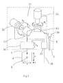
- Fig. 2 shows schematically the internal structure of the tool 3 of FIG. 1. It points to deflecting the laser beam 5 a scanner system 3.1 consisting of mirrors 3.2, 3.3 and assigned drives 3.4, 3.5. The mirrors in the A focusing lens 3.6 is connected downstream of the beam path.
- the tool 3 also includes a control unit 3.7, the signals of the control unit via the transmission medium 2.8 2.3 (Fig. 1) for controlling the drive 3.4, 3.5 and to adjust the optics 3.6 in real time.
- the three degrees of freedom of the tool movement in the exemplary embodiment in FIG. 2 of the movement of the laser beam 5 on the workpiece 4, are denoted by F 7 to F 9 in FIG. 2.
- these degrees of freedom F 7 -F 9 correspond in the selected representation according to FIG. 2 to Cartesian displacements in the X, Y and Z directions, as in the lower part of FIG. 2 in a tilted manner relative to the rest of FIG. 2 Representation is shown.
- the Z direction corresponds to the focusing degree of freedom F 9 of the tool 3.
- a coupling E of laser energy takes place in the range of Coupling unit 3.8, which is an alternative to that in FIG. 2 shown execution also outside the tool 3 in the area the fifth or sixth robot axis can be.
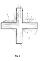
- Fig. 3 shows schematically one using the inventive Device and the method according to the invention realizable simply connected machining geometry, i.e. a trajectory B of the tool tip (TCP) in the form a cross-shaped contour, for example for laser marking the surface of a workpiece 4.
- the machining path B is shown superimposed in FIG. 3 on a movement path B 'of the robot 2 (Fig. 1) or the distal end 2.2 of the robot arm 2.1, on which, according to the invention Tool 3 can be attached.
- the trajectory B 'of Robot points in particular in areas 6, 6 'where a course of the machining path B changes significantly, i.e. clearly at corners or edges of the processing path B.
- the robot movement B runs during the entire machining process within a spatial region B''(“movementhose”; shown hatched in FIG. 3), which surrounds the machining path B on all sides, and its deviation ⁇ B from the machining path B in each case a maximum movement amplitude of the tool 3 corresponds to one of its three degrees of freedom F 7 -F 9 (see FIG. 2).
- the points P along the machining path B set the interpolation clock (IPO clock) of the control unit 2.3 of the device 1 according to the invention (FIG. 1).
- the regular Sequence of points P along the processing path B indicates that the machining of the workpiece 4 according to the invention takes place with constant processing speed. With previously known processing devices or methods corresponds to the movement path B 'of the handling device 2 essentially the specified processing path B.
- this disadvantage in particular avoided that due to the combined real-time motion control of handling device 2 and tool 3 of this compensates for the negative inertia effect of the robot axes is that this in their movement B 'in certain Areas 6, 6 'of a predetermined machining path B leading or lagging and possibly deviating from this, while traversing the machining path B in these areas 6, 6 'ensured by the tool 3's own movements is that regularly with greater speed are feasible.
- the handling device shortens 2 in difficult areas of the machining contour a length of its path movement B 'and leaves that Traversing the machining path B 'in these areas Tool 3 itself, so that not the machining process as whole negative due to the inertia of the handling device 2 being affected.
- the machining path B is in the storage unit shown in FIG. 1 2.4 of the control unit 2.3 of the invention Device 1 in the form of time around the value T. spaced coordinate values stored.
- the machining path B is also used in FIG. 1 determination unit shown 2.5.
- the Processor means 2.7 also shown in FIG the determination means 2.6 interact, by means of which by dynamically determining a relative pose (location and Alignment) between the tool tip of the invention Device and a sum of the coordinate values the machining path B and the associated deviations ⁇ B it is ensured that the machining path B despite dynamic Adaptation of the robot movement B 'and / or the Own movements X, Y, Z of tool 3 are observed at all times becomes.
- control unit 2.3 (Fig. 1) adjusted after the optimization of the movement path B ' Control signals to the control unit 3.7 of the tool 3. So the own movement X, Y, Z of the tool 3 "complement" the movement path B 'to the machining path B.
- FIG. 4 shows a further possible movement path B 'of the Handling device 2 for traversing the predetermined, cross-shaped Machining path B of Fig. 3.
- the embodiment 4 is only the within the Contour of the processing path B lying area of the processing hose B '' exploited.
- Such movement control of the handling device 2 is particularly advantageous if if more extensive robot movements B 'due external obstacles are not realizable or in other A particularly component-optimized movement path B 'is required or is aimed.
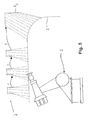
- FIG. 5 shows schematically the use of the method according to the invention or a device according to the invention in a workpiece machining in which the tool tip does not run a simply connected path on the workpiece; rather, the machining geometry J of FIG. 5 results as a sequence of piece-wise connected geometrical parts B J , B J 'in the context of a so-called step function.
- the tool tip performs a jumping movement J 'between the connected sections B J , which occurs at a speed 100 to 1000 times higher than the machining movement during the movement on the sections B J , B J ', so that no process time is lost.
- any machining geometries (even in three dimensions) can be jumped to with a robot movement from the path function last processed (machining mode with simply connected path). Since the jumps have a short duration (a few ⁇ s), it is possible not to switch off the laser power completely during the jumps, but only to reduce them by means of so-called ramps. Since the jumps take place at a higher speed than the machining movements (see above), no laser traces can be seen on the workpieces. The geometries can differ from jump to jump, so that fonts or graphics can also be created.
- step functions is a sequence of isolated, ie spatially separated, welding points.
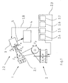
- FIG. 6 shows the sequence using a flow chart of a machining method according to the invention one equipped with a laser processing tool 3 Industrial robot 2.
- the control method shown in FIG. 6 runs according to the invention in the control unit 2.3 of the handling device 2 shown in FIG. 1.
- step S1 The starting point of the method in step S1 is a determination of the robot type (number of axes) and possibly the coordinate system used for motion control (eg Cartesian). Subsequently in step S2 there is a query as to whether the laser processing tool 3 used has three independent degrees of freedom of movement, here in particular two mirror axes F 7 , F 8 and a focus axis F 9 . If query S2 is answered in the negative, the tool axes are moved according to the prior art, either synchronously or asynchronously to robot movement S3. Otherwise, in step S4 there is a query as to whether synchronous tool control (mirror focus control) is to be taken over by control unit 2.3 of robot 2. In this case, the question is asked in step S5 as to whether movement coordination should take place between the robot and the tool.
- step S2 there is a query as to whether synchronous tool control (mirror focus control) is to be taken over by control unit 2.3 of robot 2. In this case, the question is asked in step S5 as
- step S4 Under a synchronous tool control according to step S4 is to understand a higher-level path planning that the Robots and the mirrors synchronize the positions to be approached telling. This happens, for example, in the IPO cycle by an external computer in step S6 (see below), which the Cycle for both motion controls (robot and tool) indicates synchronously.
- the movement coordination according to step S5 settles the position system of the mirror control on the three-dimensional Tool data system (TCP coordination) of the robot on.
- step S6 a coordination and movement control of the Axes by an external control unit (not shown).
- step S7 another query as to whether the specified machining path B identical to an action path, here a laser path.
- the machining path is usually outside the robot path, to take advantage of the mirrors' speed advantages.
- an editing mode is also possible in which the machining geometry is virtually on the robot path located and only corners or tight radii of the contour in one "Smoothing mode" of the TCP movement can be processed.
- the robot travels along a path that e.g. Corners of the machining contour "cut off", similar to that in Fig. 3 shown at reference numeral 6, the robot track also an arched one in the room (“rounding ball”) can be.
- step S9 begins immediately afterwards the coordinated movement of the tool (Scanner) 3 and handling device 2.
- step S8.1 the machining path B (and the laser path) into discrete point sequences of Coordinate values based on a time grid Required by the reachable IPO cycles of the handling device 2 or its control unit 2.3 disassembled.
- T Fig. 3
- Positions determined and in a storage unit 2.4 Control unit 2.3 are stored, for example in Form a database.
- step S8.2 for every IPO cycle a path difference between the given Machining path B and a taught robot path, their coordinate values also in the storage unit 2.4 of the control unit 2.3 may be stored can.
- step S8.4 The path differences are then in step S8.4 through the determination means 2.6 with the maximum permissible Deviations ⁇ B compared to the machining path B, whereupon the taught path movement of the handling device and the tool's own movements depend on it, i.e. the Mirror positions and the laser focus may be adjusted in this way that the trajectory B 'of the robot within of the movement tube B '' defined in FIG. 3.
- step S8.4 an automatic minimization continues for the IPO points P (Fig. 3, 4) for that in sections the movement path B, in which there is a processing speed or a direction of the machining path B not or only slightly changed, with one if possible small number of IPO points (coordinate values) and longer IPO cycles are used. It is in this way possible in such areas the handling device 2 faster with extrapolated coordinate values to move.
- the technique of automatic minimization refers to the Reduction of the IPO points on the robot track. For example is required for a straightforward movement of the TCP only two bases. When cornering at high speed are e.g. with high required accuracy Large number of railroad bases required in IPO cycle. Is the path speed or the path accuracy to be achieved lowered, fewer railway bases may be sufficient on the robot track.
- the automatic minimization depends on the desired accuracy of the Systems and selects the maximum necessary railway bases offline on the robot track. The mirrors themselves are approached, however, in a multiple of the IPO cycle.
- Step S8.4 is followed by a step S8.5 Query whether additional machining geometries apart from the actual machining path B are to be approached.
- This is to be understood as follows: drives an inventive one Device web functions, such as longer seams (also off the robot path), can be used as the next processing mode also follow a jump function, then again a longer seam (i.e. a sheet) etc. door corners for example welded as a seam; followed by five bracket-like edges that replace welding spots.
- On this Ways can have path functions and different geometries be mixed, e.g. Lines, circles, brackets, letters, ASCII characters and the two-dimensional and three-dimensional characters that can be generated from them Geometries. If the answer to this query is yes, then carried out steps S8 and S9 already explained above, otherwise it starts directly at S8.4 or S8.5 the coordinated movement of tool 3 and robot 2 in step S9.
Landscapes
- Engineering & Computer Science (AREA)
- Physics & Mathematics (AREA)
- Optics & Photonics (AREA)
- Mechanical Engineering (AREA)
- Robotics (AREA)
- Plasma & Fusion (AREA)
- Manipulator (AREA)
- Laser Beam Processing (AREA)
- Numerical Control (AREA)
Abstract
Description
- Fig. 1
- ein Ausführungsbeispiel der erfindungsgemäßen Vorrichtung in Form eines Sechsachs-Industrieroboters mit einem am distalen Ende des Roboterarms angeordneten Laser-Bearbeitungswerkzeug;
- Fig. 2
- eine schematische Darstellung der Ablenkung eines zur Werkstückbearbeitung eingesetzten Laserstrahls durch die Optik des Scannersystems;
- Fig. 3
- eine zusammenhängende Bearbeitungsgeometrie (Bearbeitungsbahn) für ein Werkstück mit überlagerter Bahnbewegung des Handhabungsgeräts;
- Fig. 4
- die Bearbeitungsbahn gemäß Fig. 3 mit einer anderen überlagerten Bahnbewegung des Handhabungsgeräts;
- Fig. 5
- eine schematische Darstellung einer stückweise zusammenhängenden Bearbeitungsgeometrie (Sprungfunktion) mit einer zugehörigen Bahnbewegung des Handhabungsgeräts; und
- Fig. 6
- ein Ablaufdiagramm des erfindungsgemäßen Verfahrens zur Bearbeitung von Werkstücken.
- 1
- Vorrichtung zum Bearbeiten von Werkstücken
- 2
- Handhabungsgerät/Roboter
- 2.1
- Roboterarm
- 2.2
- distales Ende (von 2.1)
- 2.3
- Steuerungseinheit
- 2.4
- Speichereinheit
- 2.5
- Bestimmungseinheit
- 2.6
- Bestimmungsmittel
- 2.7
- Prozessormittel
- 2.8
- Übertragungsmedium
- 3
- Werkzeug/Laser-Bearbeitungswerkzeug
- 3.1
- Scannersystem
- 3.2, 3.3
- Ablenkspiegel
- 3.4, 3.5
- Antrieb
- 3.6
- Fokussieroptik
- 3.7
- Steuerungseinheit
- 3.8
- Einkopplungselement
- 4
- Werkstück
- 5
- Laserstrahl
- 6, 6'
- Abschnitt (von B)
- B
- Bearbeitungsbahn
- B'
- Bewegungsbahn
- B''
- Bewegungsschlauch
- ΔB
- Abweichung
- BJ, BJ'
- zusammenhängende Teilstücke
- E
- Einkopplung (des Laserstrahls 5)
- F1-F9
- Freiheitsgrad
- J
- Bearbeitungsgeometrie (Sprungfunktion)
- P
- IPO-Punkt
- S1-S9
- Verfahrensschritte
- t
- Bearbeitungszeit
- T
- IPO-Taktzeit
- X, Y, Z
- kartesische Koordinate
Claims (24)
- Verfahren zum Bearbeiten von Werkstücken mittels eines mehrachsigen Handhabungsgeräts, wie eines Industrieroboters, mit einem nach Maßgabe durch eine Steuerungseinheit des Handhabungsgeräts bewegten Werkzeug, das Eigenbewegungen mit mehreren Freiheitsgraden ausführen kann, dadurch gekennzeichnet, dass die Freiheitsgrade des Werkzeugs gemeinsam mit Freiheitsgraden von Achsen des Handhabungsgeräts in Echtzeit zum Bewegen einer Werkzeugspitze (TCP) gemäß einer vorbestimmten Bearbeitungsgeometrie und zur Bestimmung einer Bewegung des Handhabungsgeräts ausgewertet werden.
- Verfahren nach Anspruch 1, dadurch gekennzeichnet, dass die Werkzeugspitze (TCP) zumindest zeitweise entlang einer einfach zusammenhängenden Bearbeitungsgeometrie (Bearbeitungsbahn) bewegt wird.
- Verfahren nach Anspruch 1 oder 2, dadurch gekennzeichnet, dass die Werkzeugspitze zumindest zeitweise entlang einer stückweise zusammenhängenden Bearbeitungsgeometrie bewegt wird (Sprungfunktion).
- Verfahren nach einem der Ansprüche 1 bis 3, dadurch gekennzeichnet, dass die Auswertung durch die Steuerungseinheit des Handhabungsgeräts vorgenommen wird.
- Verfahren nach einem der Ansprüche 1 bis 4, dadurch gekennzeichnet, dass für eine Bewegungssteuerung der Werkzeugspitze zumindest Koordinaten der Bearbeitungsgeometrie in eine Steuerungseinheit des Handhabungsgeräts eingelesen werden.
- Verfahren nach Anspruch 5, dadurch gekennzeichnet, dass die Bearbeitungsgeometrie zu einer Abfolge von diskreten Koordinatenwerten mit einem gleichen zeitlichen Abstand (Taktzeit) zwischen aufeinanderfolgenden Werten diskretisiert wird.
- Verfahren nach Anspruch 6, dadurch gekennzeichnet, dass die Koordinatenwerte der Bearbeitungsgeometrie vor der Bearbeitung in einer mit der Steuerungseinheit assoziierten Speichereinheit gespeichert werden.
- Verfahren nach einem der Ansprüche 5 bis 7, dadurch gekennzeichnet, dass den Koordinaten der Bearbeitungsgeometrie Korrekturwerte zugeordnet werden, die maximalen Amplituden der Eigenbewegungen des Werkzeugs in dessen Freiheitsgraden entsprechen.
- Verfahren nach Anspruch 8, dadurch gekennzeichnet, dass eine Bewegungsbahn des Handhabungsgeräts durch die Steuerungseinheit dynamisch dadurch bestimmt wird, dass eine momentane Koordinatendifferenz zwischen der Bearbeitungsgeometrie und einer Position und Orientierung (Pose) der Werkzeugspitze nicht größer als die Amplitude der entsprechenden Eigenbewegungen des Werkzeugs ist.
- Verfahren nach einem der Ansprüche 1 bis 9, dadurch gekennzeichnet, dass die Bewegungsbahn des Handhabungsgeräts möglichst kurz und/oder bauteilgerecht angepasst wird.
- Verfahren nach Anspruch 9 oder 10, dadurch gekennzeichnet, dass die einzelnen Koordinaten der Bewegungsbahn des Handhabungsgeräts und davon abhängig eine Pose des Werkzeugs zu den Takten der Koordinatenwerte der Bearbeitungsgeometrie bestimmt werden.
- Verfahren nach einem der Ansprüche 9 bis 11, dadurch gekennzeichnet, dass die Bewegungen des Handhabungsgeräts und des Werkzeugs zwischen den Takten durch Interpolation bestimmt werden.
- Verfahren nach einem der Ansprüche 6 bis 12, dadurch gekennzeichnet, dass die Taktzeit zumindest zeitweise an wenigstens einen Parameter der Bewegungen angepasst wird.
- Verfahren nach einem der Ansprüche 1 bis 13, dadurch gekennzeichnet, dass die Bewegung der Werkzeugspitze mit im wesentlichen konstanter Geschwindigkeit erfolgt.
- Verfahren nach einem der Ansprüche 1 bis 14, dadurch gekennzeichnet, dass eine vorbestimmte Bewegungsbahn des Handhabungsgerät vor der Bearbeitung in der mit der Steuerungseinheit assoziierten Speichereinheit gespeichert wird.
- Verfahren nach einem der Ansprüche 1 bis 15, dadurch gekennzeichnet, dass das Werkstück während der Bearbeitung durch das Handhabungsgerät bewegt wird.
- Verfahren nach einem der Ansprüche 1 bis 15, dadurch gekennzeichnet, dass das Werkzeug während der Bearbeitung durch das Handhabungsgerät bewegt wird.
- Vorrichtung zum Bearbeiten von Werkstücken, aufweisend ein mehrachsiges Handhabungsgerät mit einer Steuerungseinheit zur Bewegungssteuerung und ein Werkzeug, das zum Ausführen von Eigenbewegungen eine Mehrzahl von Freiheitsgraden aufweist, dadurch gekennzeichnet, dass das Werkzeug (3) und eine Werkzeugspitze (TCP) bei der Bearbeitung eines Werkstücks (4) in ihren Bewegungen (X, Y, Z) durch die Steuerungseinheit (2.3) des Handhabungsgeräts (2) steuerbar sind.
- Vorrichtung nach Anspruch 18, dadurch gekennzeichnet, dass das Werkstück (4) während der Bearbeitung mit dem Handhabungsgerät (2) verbunden und durch dieses bewegbar ist.
- Vorrichtung nach Anspruch 18, dadurch gekennzeichnet, dass das Werkzeug (3) während der Bearbeitung mit dem Handhabungsgerät (2) verbunden und durch dieses bewegbar ist.
- Vorrichtung nach einem der Ansprüche 18 bis 20, gekennzeichnet durch eine mit der Steuerungseinheit (2.3) des Handhabungsgeräts (2) assoziierte Speichereinheit (2.4) zum Speichern zumindest einer diskretisierten Abfolge von Koordinatenwerten für eine Bearbeitungsgeometrie (B) des Werkstücks (4).
- Vorrichtung nach Anspruch 21, gekennzeichnet durch eine Bestimmungseinheit (2.5) zum Bestimmen von Amplituden der Eigenbewegungen (X, Y, Z) des Werkzeugs (3) entsprechenden Abweichungen (ΔB) für die Koordinatenwerte der Bearbeitungsgeometrie (B).
- Vorrichtung nach Anspruch 22, gekennzeichnet durch Bestimmungsmittel (2.6) zum dynamischen Bestimmen einer relativen Pose zwischen Werkzeugspitze (TCP) und einer Summe aus den Koordinatenwerten der Bearbeitungsgeometrie (B) und den zugehörigen Abweichungen (ΔB), wobei in den Bestimmungsmitteln (2.6) erzeugte Signale zwecks koordinierter Bewegungssteuerung an das Handhabungsgerät (2) und das Werkzeug (3) weiterleitbar sind.
- Vorrichtung nach einem der Ansprüche 18 bis 23, gekennzeichnet durch programmtechnisch eingerichtete Prozessormittel (2.7) zum zeitlichen und/oder räumlichen Optimieren einer momentanen Bewegung (B') des Handhabungsgeräts (2) unter Ausnutzung der Freiheitsgerade (X, Y, Z) des Werkzeugs (3).
Applications Claiming Priority (2)
| Application Number | Priority Date | Filing Date | Title |
|---|---|---|---|
| DE10255037 | 2002-11-26 | ||
| DE10255037A DE10255037A1 (de) | 2002-11-26 | 2002-11-26 | Verfahren und Vorrichtung zum Bearbeiten eines Werkstücks |
Publications (2)
| Publication Number | Publication Date |
|---|---|
| EP1424613A1 true EP1424613A1 (de) | 2004-06-02 |
| EP1424613B1 EP1424613B1 (de) | 2010-04-28 |
Family
ID=32240419
Family Applications (1)
| Application Number | Title | Priority Date | Filing Date |
|---|---|---|---|
| EP03026586A Revoked EP1424613B1 (de) | 2002-11-26 | 2003-11-19 | Verfahren und Vorrichtung zum Bearbeiten eines Werkstücks |
Country Status (4)
| Country | Link |
|---|---|
| US (1) | US7292910B2 (de) |
| EP (1) | EP1424613B1 (de) |
| JP (1) | JP2004174709A (de) |
| DE (2) | DE10255037A1 (de) |
Cited By (7)
| Publication number | Priority date | Publication date | Assignee | Title |
|---|---|---|---|---|
| EP1849553A1 (de) | 2006-04-24 | 2007-10-31 | Nissan Motor Company Limited | Verbesserungen bei oder im Zusammenhang mit Strahlbestrahlungsgeräten |
| EP1943049A4 (de) * | 2005-09-30 | 2008-12-03 | Nissan Motor | Laserschweissverfahren und laserschweisssystem |
| EP1710040A3 (de) * | 2005-04-06 | 2009-03-04 | Fanuc Ltd | Laserschweißverfahren und Laserschweißroboter |
| WO2010040493A1 (de) * | 2008-10-06 | 2010-04-15 | Kuka Roboter Gmbh | Industrieroboter und bahnplanungsverfahren zum steuern der bewegung eines industrieroboters |
| EP3020518A4 (de) * | 2014-03-17 | 2016-10-26 | Panasonic Ip Man Co Ltd | Laserbearbeitungsroboter |
| EP3106943A1 (de) * | 2015-06-16 | 2016-12-21 | Erlas Erlanger Lasertechnik GmbH | Scannereinrichtung für einen laserstrahl zur lasermaterialbearbeitung, werkzeugmaschine mit der scannereinrichtung sowie verfahren zum ansteuern der werkzeugmaschine mit der scannereinrichtung |
| CN111716127A (zh) * | 2020-07-02 | 2020-09-29 | 上海营创精密汽车模型技术有限公司 | 一种多自由度夹具 |
Families Citing this family (34)
| Publication number | Priority date | Publication date | Assignee | Title |
|---|---|---|---|---|
| DE10351670A1 (de) * | 2003-11-05 | 2005-06-30 | Kuka Roboter Gmbh | Verfahren und Vorrichtung zum Steuern von Robotern |
| DE102004026814A1 (de) * | 2004-06-02 | 2005-12-29 | Kuka Roboter Gmbh | Verfahren und Vorrichtung zum Verbessern der Positioniergenauigkeit eines Handhabungsgeräts |
| DE202004021568U1 (de) * | 2004-10-20 | 2009-04-23 | Robot-Technology Gmbh | Roboter |
| JP4220958B2 (ja) * | 2004-11-30 | 2009-02-04 | ファナック株式会社 | レーザ加工ロボットシステム及びその制御方法 |
| JP4922584B2 (ja) * | 2004-12-10 | 2012-04-25 | 株式会社安川電機 | ロボットシステム |
| JP4792740B2 (ja) * | 2004-12-16 | 2011-10-12 | 日産自動車株式会社 | レーザ溶接の制御装置および制御方法 |
| JP2006247677A (ja) * | 2005-03-09 | 2006-09-21 | Fanuc Ltd | レーザ溶接教示装置及び方法 |
| US20070283780A1 (en) * | 2006-05-02 | 2007-12-13 | Ed Smock | Automated Device and Method for Manufacturing a Door |
| US8577499B2 (en) * | 2008-11-19 | 2013-11-05 | Abb Technology Ab | Method and a device for optimizing a programmed movement path for an industrial robot |
| DE102009023297A1 (de) * | 2009-05-29 | 2010-12-02 | Kuka Roboter Gmbh | Verfahren und Vorrichtung zum Betrieb einer zusätzlichen Werkzeugachse eines von einem Manipulator geführten Werkzeugs |
| DE102009023307A1 (de) * | 2009-05-29 | 2010-12-02 | Kuka Roboter Gmbh | Verfahren und Vorrichtung zur Steuerung eines Manipulators |
| CN102448682A (zh) * | 2009-06-30 | 2012-05-09 | 株式会社爱发科 | 机器人示教装置及机器人示教方法 |
| DE102009049172B4 (de) * | 2009-10-13 | 2019-07-25 | Kuka Roboter Gmbh | Verfahren und Vorrichtung zur Steuerung eines Manipulators |
| US10072971B2 (en) * | 2010-04-16 | 2018-09-11 | Metal Improvement Company, Llc | Flexible beam delivery system for high power laser systems |
| ITTO20100936A1 (it) * | 2010-11-25 | 2012-05-26 | Windco S R L | Macchina laser e procedimenti per il suo utilizzo. |
| DE102011079116A1 (de) * | 2011-07-14 | 2013-01-17 | Kuka Roboter Gmbh | Verfahren zum Überprüfen der Plausibilität der Ausgangssignale eines Resolvers |
| US8921734B2 (en) | 2011-11-10 | 2014-12-30 | Mitsubishi Electric Research Laboratories, Inc. | Laser cutting machine |
| US10589973B2 (en) | 2013-10-25 | 2020-03-17 | Ats Automation Tooling Systems Inc. | Flexible feeding and closing machine for hinged caps |
| DE102015209916A1 (de) * | 2015-05-29 | 2016-12-01 | Zf Friedrichshafen Ag | Regelung eines spanenden Bearbeitungsprozesses mittels P-Regler und belastungsabhängigem Regelfaktor |
| EP3183093B1 (de) | 2015-06-22 | 2020-08-05 | Electro Scientific Industries, Inc. | Mehrachsiges maschinenwerkzeug und verfahren zur steuerung davon |
| DE102015008188B3 (de) * | 2015-06-25 | 2016-06-16 | Kuka Roboter Gmbh | Abfahren einer vorgegebenen Bahn mit einem Roboter |
| US9757859B1 (en) * | 2016-01-21 | 2017-09-12 | X Development Llc | Tooltip stabilization |
| US9744665B1 (en) | 2016-01-27 | 2017-08-29 | X Development Llc | Optimization of observer robot locations |
| US10059003B1 (en) | 2016-01-28 | 2018-08-28 | X Development Llc | Multi-resolution localization system |
| JP6325646B1 (ja) | 2016-12-12 | 2018-05-16 | ファナック株式会社 | ロボットを用いてレーザ加工を行うレーザ加工ロボットシステム及びレーザ加工ロボットの制御方法 |
| JP6457473B2 (ja) * | 2016-12-16 | 2019-01-23 | ファナック株式会社 | ロボットおよびレーザスキャナの動作を学習する機械学習装置,ロボットシステムおよび機械学習方法 |
| JP6496340B2 (ja) * | 2017-03-17 | 2019-04-03 | ファナック株式会社 | スキャナ制御装置、ロボット制御装置及びリモートレーザ溶接ロボットシステム |
| US10060857B1 (en) * | 2017-11-16 | 2018-08-28 | General Electric Company | Robotic feature mapping and motion control |
| US20210394306A1 (en) * | 2018-09-28 | 2021-12-23 | Makino Milling Machine Co., Ltd. | Laser machining apparatus |
| JP7122221B2 (ja) * | 2018-10-26 | 2022-08-19 | オークマ株式会社 | 工作機械 |
| CN112427802A (zh) * | 2019-08-23 | 2021-03-02 | 湖北航鹏化学动力科技有限责任公司 | 一种激光自动焊接装置 |
| EP4246257A1 (de) | 2022-03-18 | 2023-09-20 | Siemens Aktiengesellschaft | Geschwindigkeitsabhängiges überschleifen zwischen sätzen mit unstetigen bahnverläufen |
| DE102022213536A1 (de) * | 2022-12-13 | 2024-06-13 | Robert Bosch Gesellschaft mit beschränkter Haftung | Verfahren zum Herstellen eines Sensors und Sensor |
| CN121844254A (zh) * | 2023-09-12 | 2026-04-10 | Asml荷兰有限公司 | 设定点生成器、位置控制系统、平台装置和曝光装置 |
Citations (5)
| Publication number | Priority date | Publication date | Assignee | Title |
|---|---|---|---|---|
| US4694139A (en) | 1984-12-03 | 1987-09-15 | Messer Griesheim Gmbh | Guidance device for a laser beam for three-dimensional machining of workpieces |
| US4891765A (en) | 1987-03-04 | 1990-01-02 | Hitachi, Ltd. | Control system |
| EP0671246A2 (de) | 1994-03-09 | 1995-09-13 | Siemens Aktiengesellschaft | Greiferbezogenes Handverfahren |
| EP0941815A2 (de) | 1998-03-10 | 1999-09-15 | Fanuc Ltd | Robotersystem und Bearbeitungsverfahren mit einem Robotersystem |
| EP1038640A2 (de) | 1999-03-25 | 2000-09-27 | Fanuc Ltd. | Manipulatorsteuerung |
Family Cites Families (19)
| Publication number | Priority date | Publication date | Assignee | Title |
|---|---|---|---|---|
| JPS6148006A (ja) * | 1984-08-14 | 1986-03-08 | Kobe Steel Ltd | 工業用ロボツトの教示デ−タ編集方式 |
| JPS6380307A (ja) * | 1986-09-25 | 1988-04-11 | Kobe Steel Ltd | 産業用ロボツトの速度制御方法 |
| JP2708458B2 (ja) * | 1988-04-01 | 1998-02-04 | 株式会社豊田中央研究所 | 倣い制御ロボット |
| JP2676793B2 (ja) * | 1988-06-30 | 1997-11-17 | トヨタ自動車株式会社 | 倣い制御ロボット |
| US5737500A (en) * | 1992-03-11 | 1998-04-07 | California Institute Of Technology | Mobile dexterous siren degree of freedom robot arm with real-time control system |
| JPH0663880A (ja) * | 1992-08-19 | 1994-03-08 | Orii:Kk | ワーク移送用6軸スカラロボット |
| JPH0683416A (ja) * | 1992-09-04 | 1994-03-25 | Komatsu Ltd | 小図形加工ユニットを有したロボットの制御装置 |
| JPH0732282A (ja) * | 1993-07-19 | 1995-02-03 | Toyoda Mach Works Ltd | ロボット制御装置 |
| DE19507561A1 (de) * | 1994-03-09 | 1995-09-14 | Siemens Ag | Verfahren und Vorrichtung zum Überschleifen bei numerisch gesteuerten Maschinen |
| JPH08292809A (ja) * | 1995-04-20 | 1996-11-05 | Mitsubishi Electric Corp | 数値制御方法および数値制御装置 |
| DE19626459C2 (de) * | 1996-07-02 | 1999-09-02 | Kuka Schweissanlagen Gmbh | Verfahren und Vorrichtung zum Teachen eines programmgesteuerten Roboters |
| DE19648430A1 (de) * | 1996-11-22 | 1998-05-28 | Heidel Gmbh & Co Kg Werkzeug U | Vorrichtung und Verfahren zur Bearbeitung von Werkstücken |
| JP3673383B2 (ja) * | 1997-12-12 | 2005-07-20 | ファナック株式会社 | ロボットの制御装置 |
| US6070109A (en) * | 1998-03-10 | 2000-05-30 | Fanuc Robotics North America, Inc. | Robot calibration system |
| JP2000141256A (ja) * | 1998-11-04 | 2000-05-23 | Hitachi Zosen Corp | ロボット装置の制御方法 |
| DE19857436A1 (de) * | 1998-12-12 | 2000-06-21 | Kuka Roboter Gmbh | Verfahren zum Behandeln des Spannungsabfalls in der Steuerung eines Roboters und zum Wiederanfahren eines Roboters nach Spannungsabfall |
| US6451232B2 (en) | 1999-03-25 | 2002-09-17 | Lear Corporation | Method for forming headliners |
| JP2001225286A (ja) * | 2000-02-14 | 2001-08-21 | Nachi Fujikoshi Corp | 搬送装置 |
| SE0001312D0 (sv) * | 2000-04-10 | 2000-04-10 | Abb Ab | Industrirobot |
-
2002
- 2002-11-26 DE DE10255037A patent/DE10255037A1/de not_active Ceased
-
2003
- 2003-11-19 DE DE50312659T patent/DE50312659D1/de not_active Expired - Lifetime
- 2003-11-19 EP EP03026586A patent/EP1424613B1/de not_active Revoked
- 2003-11-24 US US10/723,695 patent/US7292910B2/en not_active Expired - Lifetime
- 2003-11-25 JP JP2003393827A patent/JP2004174709A/ja active Pending
Patent Citations (5)
| Publication number | Priority date | Publication date | Assignee | Title |
|---|---|---|---|---|
| US4694139A (en) | 1984-12-03 | 1987-09-15 | Messer Griesheim Gmbh | Guidance device for a laser beam for three-dimensional machining of workpieces |
| US4891765A (en) | 1987-03-04 | 1990-01-02 | Hitachi, Ltd. | Control system |
| EP0671246A2 (de) | 1994-03-09 | 1995-09-13 | Siemens Aktiengesellschaft | Greiferbezogenes Handverfahren |
| EP0941815A2 (de) | 1998-03-10 | 1999-09-15 | Fanuc Ltd | Robotersystem und Bearbeitungsverfahren mit einem Robotersystem |
| EP1038640A2 (de) | 1999-03-25 | 2000-09-27 | Fanuc Ltd. | Manipulatorsteuerung |
Cited By (14)
| Publication number | Priority date | Publication date | Assignee | Title |
|---|---|---|---|---|
| EP1710040A3 (de) * | 2005-04-06 | 2009-03-04 | Fanuc Ltd | Laserschweißverfahren und Laserschweißroboter |
| EP1943049A4 (de) * | 2005-09-30 | 2008-12-03 | Nissan Motor | Laserschweissverfahren und laserschweisssystem |
| US9000327B2 (en) | 2005-09-30 | 2015-04-07 | Nissan Motor Co., Ltd. | Laser welding method and laser welding system |
| EP1849553A1 (de) | 2006-04-24 | 2007-10-31 | Nissan Motor Company Limited | Verbesserungen bei oder im Zusammenhang mit Strahlbestrahlungsgeräten |
| US9050687B2 (en) | 2006-04-24 | 2015-06-09 | Nissan Motor Co., Ltd. | Apparatus and method for recognizing irradiation-enabled area of beam irradiating device and for establishing a moving path of the device |
| WO2010040493A1 (de) * | 2008-10-06 | 2010-04-15 | Kuka Roboter Gmbh | Industrieroboter und bahnplanungsverfahren zum steuern der bewegung eines industrieroboters |
| EP3020518A4 (de) * | 2014-03-17 | 2016-10-26 | Panasonic Ip Man Co Ltd | Laserbearbeitungsroboter |
| CN106103015A (zh) * | 2014-03-17 | 2016-11-09 | 松下知识产权经营株式会社 | 激光加工机器人 |
| US10101724B2 (en) | 2014-03-17 | 2018-10-16 | Panasonic Intellectual Property Management Co., Ltd. | Laser machining robot |
| CN106103015B (zh) * | 2014-03-17 | 2019-05-10 | 松下知识产权经营株式会社 | 激光加工机器人 |
| EP3106943A1 (de) * | 2015-06-16 | 2016-12-21 | Erlas Erlanger Lasertechnik GmbH | Scannereinrichtung für einen laserstrahl zur lasermaterialbearbeitung, werkzeugmaschine mit der scannereinrichtung sowie verfahren zum ansteuern der werkzeugmaschine mit der scannereinrichtung |
| DE102015109593A1 (de) * | 2015-06-16 | 2016-12-22 | Erlas Erlanger Lasertechnik Gmbh | Scannereinrichtung für einen Laserstrahl zur Lasermaterialbearbeitung, Werkzeugmaschine mit der Scannereinrichtung sowie Verfahren zum Ansteuern der Werkzeugmaschine mit der Scannereinrichtung |
| DE102015109593B4 (de) | 2015-06-16 | 2022-02-10 | Erlas Erlanger Lasertechnik Gmbh | Scannereinrichtung für einen Laserstrahl zur Lasermaterialbearbeitung, Werkzeugmaschine mit der Scannereinrichtung sowie Verfahren zum Ansteuern der Werkzeugmaschine mit der Scannereinrichtung |
| CN111716127A (zh) * | 2020-07-02 | 2020-09-29 | 上海营创精密汽车模型技术有限公司 | 一种多自由度夹具 |
Also Published As
| Publication number | Publication date |
|---|---|
| JP2004174709A (ja) | 2004-06-24 |
| DE50312659D1 (de) | 2010-06-10 |
| EP1424613B1 (de) | 2010-04-28 |
| DE10255037A1 (de) | 2004-06-09 |
| US20040111185A1 (en) | 2004-06-10 |
| US7292910B2 (en) | 2007-11-06 |
Similar Documents
| Publication | Publication Date | Title |
|---|---|---|
| EP1424613B1 (de) | Verfahren und Vorrichtung zum Bearbeiten eines Werkstücks | |
| EP2303521B1 (de) | Industrieroboter und bahnplanungsverfahren zum steuern der bewegung eines industrieroboters | |
| EP2255931B1 (de) | Verfahren und Vorrichtung zur Steuerung eines Manipulators | |
| EP2285537B1 (de) | Vorrichtung und verfahren zur rechnergestützten generierung einer manipulatorbahn | |
| EP1727645B1 (de) | Verfahren zum laserbearbeiten und lasereinrichtung mit in abhängigkeit von der laserbewegung gesteuerter laserleistung | |
| DE69331787T2 (de) | Robotische Bewegung eines Gegenstanden über einer Werkstücksfläche | |
| AT398050B (de) | Schweissroboter | |
| DE102009049172B4 (de) | Verfahren und Vorrichtung zur Steuerung eines Manipulators | |
| EP1591209A2 (de) | Verfahren zum Steuern einer Maschine, insbesondere eines Industrieroboters | |
| DE102013112516B4 (de) | Lehrpunktprogramm-Auswahlverfahren für Robotersimulator | |
| DE102018218033B4 (de) | Laserbearbeitungssystem | |
| DE3144843A1 (de) | Verfahren zum betreiben eines als schweissroboter arbeitenden manipulators und dementsprechende steuerung | |
| EP3509802B1 (de) | Optimierungsverfahren für einen beschichtungsroboter und entsprechende beschichtungsanlage | |
| WO2013037693A2 (de) | System und verfahren zur automatisierten erstellung von roboterprogrammen | |
| DE112010000794T5 (de) | Verfahren zum Steuern eines Roboterwerkzeugs | |
| DE10242710A1 (de) | Verfahren zum Herstellen eines Verbindungsbereiches auf einem Werkstück | |
| DE102015223258A1 (de) | Verfahren zum Bearbeiten der Oberfläche eines dreidimensionalen Objekts | |
| EP0530401B1 (de) | Verfahren zum Auslösen von positionsbezogenen Schaltvorgängen während eines von einem Roboter oder einer Werkzeugmaschine ausgeführten Bearbeitungsvorganges | |
| EP3569367A1 (de) | Rechnergestütztes ermitteln einer bewegung einer vorrichtung | |
| DE102019106360B4 (de) | Betriebsprogrammeinstellungsvorrichtung für roboter, roboter und verfahren zum steuern des roboters | |
| EP3106943B1 (de) | Scannereinrichtung für einen laserstrahl zur lasermaterialbearbeitung, werkzeugmaschine mit der scannereinrichtung sowie verfahren zum ansteuern der werkzeugmaschine mit der scannereinrichtung | |
| DE102008013398A1 (de) | Verfahren zur Programmierung und Steuerung einer Remote-Bearbeitungsanlage | |
| DE202004003775U1 (de) | Lasereinrichtung | |
| DE102020104362B4 (de) | Bahnplanung für einen Robotermanipulator mittels Kamerabild | |
| EP2420360B1 (de) | Verfahren und Programmiermittel zum Programmieren eines Roboters |
Legal Events
| Date | Code | Title | Description |
|---|---|---|---|
| PUAI | Public reference made under article 153(3) epc to a published international application that has entered the european phase |
Free format text: ORIGINAL CODE: 0009012 |
|
| AK | Designated contracting states |
Kind code of ref document: A1 Designated state(s): AT BE BG CH CY CZ DE DK EE ES FI FR GB GR HU IE IT LI LU MC NL PT RO SE SI SK TR |
|
| AX | Request for extension of the european patent |
Extension state: AL LT LV MK |
|
| RTI1 | Title (correction) |
Free format text: METHOD AND DEVICE FOR MACHINING A WORKPIECE |
|
| AKX | Designation fees paid | ||
| 17P | Request for examination filed |
Effective date: 20040727 |
|
| RBV | Designated contracting states (corrected) |
Designated state(s): DE FR GB IT SE |
|
| REG | Reference to a national code |
Ref country code: DE Ref legal event code: 8566 |
|
| 17Q | First examination report despatched |
Effective date: 20060123 |
|
| GRAP | Despatch of communication of intention to grant a patent |
Free format text: ORIGINAL CODE: EPIDOSNIGR1 |
|
| GRAS | Grant fee paid |
Free format text: ORIGINAL CODE: EPIDOSNIGR3 |
|
| GRAA | (expected) grant |
Free format text: ORIGINAL CODE: 0009210 |
|
| RAP1 | Party data changed (applicant data changed or rights of an application transferred) |
Owner name: KUKA ROBOTER GMBH |
|
| AK | Designated contracting states |
Kind code of ref document: B1 Designated state(s): DE FR GB IT SE |
|
| REG | Reference to a national code |
Ref country code: GB Ref legal event code: FG4D Free format text: NOT ENGLISH |
|
| REF | Corresponds to: |
Ref document number: 50312659 Country of ref document: DE Date of ref document: 20100610 Kind code of ref document: P |
|
| REG | Reference to a national code |
Ref country code: SE Ref legal event code: TRGR |
|
| PLBI | Opposition filed |
Free format text: ORIGINAL CODE: 0009260 |
|
| 26 | Opposition filed |
Opponent name: YASKAWA EUROPE GMBH Effective date: 20110127 |
|
| PLAX | Notice of opposition and request to file observation + time limit sent |
Free format text: ORIGINAL CODE: EPIDOSNOBS2 |
|
| GBPC | Gb: european patent ceased through non-payment of renewal fee |
Effective date: 20101119 |
|
| PLBB | Reply of patent proprietor to notice(s) of opposition received |
Free format text: ORIGINAL CODE: EPIDOSNOBS3 |
|
| PG25 | Lapsed in a contracting state [announced via postgrant information from national office to epo] |
Ref country code: GB Free format text: LAPSE BECAUSE OF NON-PAYMENT OF DUE FEES Effective date: 20101119 |
|
| APBM | Appeal reference recorded |
Free format text: ORIGINAL CODE: EPIDOSNREFNO |
|
| APBP | Date of receipt of notice of appeal recorded |
Free format text: ORIGINAL CODE: EPIDOSNNOA2O |
|
| APAH | Appeal reference modified |
Free format text: ORIGINAL CODE: EPIDOSCREFNO |
|
| APBQ | Date of receipt of statement of grounds of appeal recorded |
Free format text: ORIGINAL CODE: EPIDOSNNOA3O |
|
| REG | Reference to a national code |
Ref country code: DE Ref legal event code: R082 Ref document number: 50312659 Country of ref document: DE |
|
| REG | Reference to a national code |
Ref country code: FR Ref legal event code: PLFP Year of fee payment: 13 |
|
| REG | Reference to a national code |
Ref country code: FR Ref legal event code: PLFP Year of fee payment: 14 |
|
| REG | Reference to a national code |
Ref country code: FR Ref legal event code: PLFP Year of fee payment: 15 |
|
| REG | Reference to a national code |
Ref country code: DE Ref legal event code: R064 Ref document number: 50312659 Country of ref document: DE Ref country code: DE Ref legal event code: R103 Ref document number: 50312659 Country of ref document: DE |
|
| APBU | Appeal procedure closed |
Free format text: ORIGINAL CODE: EPIDOSNNOA9O |
|
| PGFP | Annual fee paid to national office [announced via postgrant information from national office to epo] |
Ref country code: FR Payment date: 20171012 Year of fee payment: 15 Ref country code: DE Payment date: 20171114 Year of fee payment: 15 |
|
| PGFP | Annual fee paid to national office [announced via postgrant information from national office to epo] |
Ref country code: IT Payment date: 20171123 Year of fee payment: 15 Ref country code: SE Payment date: 20171113 Year of fee payment: 15 |
|
| RDAF | Communication despatched that patent is revoked |
Free format text: ORIGINAL CODE: EPIDOSNREV1 |
|
| RDAG | Patent revoked |
Free format text: ORIGINAL CODE: 0009271 |
|
| 27W | Patent revoked |
Effective date: 20180110 |
|
| REG | Reference to a national code |
Ref country code: SE Ref legal event code: ECNC |