EP1424569B1 - Vorrichtung zum Auslesen von einer in einem Phosphorträger abgespeicherten Information und Röntgenkassette - Google Patents
Vorrichtung zum Auslesen von einer in einem Phosphorträger abgespeicherten Information und Röntgenkassette Download PDFInfo
- Publication number
- EP1424569B1 EP1424569B1 EP03102259A EP03102259A EP1424569B1 EP 1424569 B1 EP1424569 B1 EP 1424569B1 EP 03102259 A EP03102259 A EP 03102259A EP 03102259 A EP03102259 A EP 03102259A EP 1424569 B1 EP1424569 B1 EP 1424569B1
- Authority
- EP
- European Patent Office
- Prior art keywords
- phosphor
- radiation
- line
- phosphor carrier
- carrier
- Prior art date
- Legal status (The legal status is an assumption and is not a legal conclusion. Google has not performed a legal analysis and makes no representation as to the accuracy of the status listed.)
- Expired - Lifetime
Links
- OAICVXFJPJFONN-UHFFFAOYSA-N Phosphorus Chemical compound [P] OAICVXFJPJFONN-UHFFFAOYSA-N 0.000 claims abstract description 154
- 230000005855 radiation Effects 0.000 claims abstract description 88
- 238000003384 imaging method Methods 0.000 claims description 20
- 238000000576 coating method Methods 0.000 claims description 8
- 239000011248 coating agent Substances 0.000 claims description 5
- 238000011156 evaluation Methods 0.000 claims 2
- 238000001444 catalytic combustion detection Methods 0.000 claims 1
- 230000004936 stimulating effect Effects 0.000 claims 1
- 230000005284 excitation Effects 0.000 description 16
- 238000012545 processing Methods 0.000 description 16
- 230000003287 optical effect Effects 0.000 description 8
- 238000006243 chemical reaction Methods 0.000 description 4
- 238000013461 design Methods 0.000 description 4
- 238000012937 correction Methods 0.000 description 3
- 238000009826 distribution Methods 0.000 description 3
- 230000035945 sensitivity Effects 0.000 description 3
- 210000000988 bone and bone Anatomy 0.000 description 2
- 238000010276 construction Methods 0.000 description 2
- 239000000835 fiber Substances 0.000 description 2
- 230000007774 longterm Effects 0.000 description 2
- 210000004872 soft tissue Anatomy 0.000 description 2
- 230000000638 stimulation Effects 0.000 description 2
- 238000012935 Averaging Methods 0.000 description 1
- 230000032683 aging Effects 0.000 description 1
- 238000003491 array Methods 0.000 description 1
- 230000002146 bilateral effect Effects 0.000 description 1
- 230000005540 biological transmission Effects 0.000 description 1
- 230000003750 conditioning effect Effects 0.000 description 1
- 230000007423 decrease Effects 0.000 description 1
- 230000001419 dependent effect Effects 0.000 description 1
- 238000001514 detection method Methods 0.000 description 1
- 230000000694 effects Effects 0.000 description 1
- 239000011888 foil Substances 0.000 description 1
- 239000003365 glass fiber Substances 0.000 description 1
- 239000012216 imaging agent Substances 0.000 description 1
- 238000013507 mapping Methods 0.000 description 1
- 238000000034 method Methods 0.000 description 1
- 239000000203 mixture Substances 0.000 description 1
- 230000001105 regulatory effect Effects 0.000 description 1
- 230000003595 spectral effect Effects 0.000 description 1
Images


Classifications
-
- G—PHYSICS
- G01—MEASURING; TESTING
- G01T—MEASUREMENT OF NUCLEAR OR X-RADIATION
- G01T1/00—Measuring X-radiation, gamma radiation, corpuscular radiation, or cosmic radiation
- G01T1/16—Measuring radiation intensity
- G01T1/20—Measuring radiation intensity with scintillation detectors
- G01T1/2012—Measuring radiation intensity with scintillation detectors using stimulable phosphors, e.g. stimulable phosphor sheets
- G01T1/2014—Reading out of stimulable sheets, e.g. latent image
-
- H—ELECTRICITY
- H04—ELECTRIC COMMUNICATION TECHNIQUE
- H04N—PICTORIAL COMMUNICATION, e.g. TELEVISION
- H04N1/00—Scanning, transmission or reproduction of documents or the like, e.g. facsimile transmission; Details thereof
- H04N1/024—Details of scanning heads ; Means for illuminating the original
- H04N1/028—Details of scanning heads ; Means for illuminating the original for picture information pick-up
- H04N1/03—Details of scanning heads ; Means for illuminating the original for picture information pick-up with photodetectors arranged in a substantially linear array
- H04N1/031—Details of scanning heads ; Means for illuminating the original for picture information pick-up with photodetectors arranged in a substantially linear array the photodetectors having a one-to-one and optically positive correspondence with the scanned picture elements, e.g. linear contact sensors
Definitions
- the invention relates to a device for line-wise readout of a stored in a phosphor carrier information according to claim 1.
- the invention further relates to an X-ray cassette with a corresponding device.
- an image is generated by an object, for example a patient, by means of X-radiation, which image is stored in a phosphor carrier as a latent image.
- the phosphor carrier is excited by means of a radiation source. Due to this excitation, it emits light which has an intensity corresponding to the X-ray image stored in the phosphor carrier.
- the light emitted by the phosphor carrier is received by a detection means so that the X-ray image stored in the phosphor carrier can subsequently be made visible.
- the X-ray image can for example be displayed directly on a monitor. But it is also possible to write the X-ray image on a specially prepared for X-ray photographic X-ray film.
- the phosphor beam exciting the laser beam must meet certain conditions with respect to its spatial and spectral distribution.
- such "flying spot" systems require a laser beam guidance with a length of approximately 1.5 to 2 times the width of the line to be excited of the phosphor carrier.
- the focusing and guiding of the laser beam requires a very complex and therefore expensive system of optical components. These optical components also require a lot of space, so that the device dimensions of such a "flying spot" system are very large.
- a stimulation radiation source comprises a multiplicity of point light sources which sequentially emit stimulation beams onto the phosphor layer.
- This device does not allow much easier or more effective readout of phosphor layers than the abovementioned flying spot systems.
- the present invention has for its object to ensure a good quality in the reproduction of information stored in a phosphor carrier information.
- a plurality of individual beams can be generated by means of the radiation source, as a result of which the simultaneous excitation of a plurality of points of the phosphor carrier can be carried out very precisely in a simple and effective manner.
- the radiation source may generate at least a first radiation field and at least one second radiation field, wherein the first radiation field and the second radiation field are in an overlay field on the line overlap. In this way it is possible to increase the reliability of the radiation source, since even if one of the laser diodes, the excitation of all points of the line to be stimulated is guaranteed.
- the intensity of the exciting radiation is reduced in case of failure of one of the laser diodes in the respective failing area, however, this failure can be detected, so that the data processing device, which performs the processing of the digital image data after converting the light detected by the receiving means into electrical signals, which can correct the digital image data corrupted by the failure.
- the receiving means is designed such that it contains a plurality of point elements and the second radiation emitted by excited points of the phosphor carrier can be received point by point by a plurality of these point elements.
- a predetermined minimum energy E is necessary to excite the individual points of the phosphor carrier so that they emit the second radiation. This depends on the power (intensity) of the radiation source and the residence time of the first radiation emitted by the radiation source on the point to be excited of the phosphor carrier. If several points of the phosphor carrier are excited at the same time, it is possible to obtain a relatively long residence time of the first radiation per point of the phosphor carrier, without lengthening the total duration stored for reading out all the information stored in the phosphor carrier.
- the signal-to-noise ratio for self-noise of the dot elements can be increased. Due to the longer residence time of the first radiation of the radiation source per point of the phosphor carrier, it is also possible to reduce the power to be applied by the radiation source (intensity) while still applying the energy required for exciting the phosphor carrier.
- the radiation source has a plurality of laser diodes, which are used for the excitation of the multiple points of the phosphor carrier.
- laser diodes can be generated for the excitation of the points of the phosphor carrier sufficiently high radiation power. At the same time they are very compact, so that their use is conducive to a construction of the device according to the invention with small dimensions.
- laser diodes can be easily controlled and regulated.
- the number of laser diodes of the radiation source is equal to the number of dot elements of the receiving means.
- Each point of a line to be excited of the phosphor carrier is stimulated in this case simultaneously.
- the radiation source is then designed as a laser diode array. This makes it advantageously possible to further optical means for expanding and focusing the laser diode beams to renounce.
- the distance between the radiation source and the phosphor carrier to be excited can be kept low. This further promotes the compactness of the arrangement.
- the radiation source can contain an optical system with which the individual beam can be widened in the propagation direction of a line of the phosphor carrier.
- the excitation power to be provided by the radiation source can be reduced.
- the read-out reliability is also increased in the event of a single beam failure.
- the optics provided in the radiation source are advantageously designed such that it focuses the individual beams in a direction perpendicular to the propagation direction of the line. This ensures that unwanted excitation of lines adjacent to the line currently being scanned is avoided.
- An imaging means can be provided between the phosphor carrier and the receiving means, with which the second radiation emitted by the individual excited points of the phosphor carrier can be imaged on the individual point elements of the receiving means.
- This mapping is advantageously done in a 1: 1 scale. This makes it possible to dispense with the use of a fiber cross-section converter, which has unfavorably large dimensions. The distance between the phosphor carrier and the receiving means is thereby very low, whereby the compactness of the arrangement can be greatly improved.
- two radiation sources are provided, each of which a receiving means is assigned.
- the two radiation sources and their associated receiving means are arranged so that the phosphor carrier, which is a phosphor plate with a top and a bottom, is readable on both sides.
- the amount of second radiation to be emitted from the phosphor carrier can be further increased, thereby improving the quality of reproduction of the information read from the phosphor plate.
- a device for reading out information stored in a phosphor carrier is mounted directly in an X-ray cassette which has such a phosphor carrier.
- An X-ray information stored in the phosphor carrier can therefore be read directly from the device according to the invention and fed to a control device for further processing.
- Such an X-ray cassette can advantageously be integrated permanently in an X-ray machine. As a result, it is advantageously no longer necessary for the operating personnel, in order to read out the information stored in the phosphor carrier, to remove the X-ray cassette from the X-ray apparatus in order to insert it into a special reading device for reading out the stored information. The ease of use is thereby greatly improved.
- the phosphor carrier is designed as a phosphor plate which has a top and a bottom, which have different coatings from each other. These two different coatings have different sensitivities.
- the phosphor plate for example, bones can be better recorded, and by coating the other side of the phosphor plate, for example, soft tissues.
- the operator has due to this embodiment of the X-ray cassette according to the invention the choice between two sensitivities. This can the flexibility and performance of the device according to the invention can be further increased.
- FIG. 1 shows the first embodiment of the inventive device for reading from a stored in a phosphor carrier information.
- a reading head 10 is used to read out image information from a phosphor plate 15. This image information was generated by X-irradiation in the phosphor plate 15.
- the reading head 10 has a radiation source, which is designed here as a laser diode array 11.
- the laser diode array 11 is aligned perpendicular to the phosphor plate 15, so that the radiation emitted by the individual laser diode radiation strikes the phosphor plate directly.
- the laser diode array 11 has a multiplicity of laser diodes arranged next to one another, which in the present exemplary embodiment can excite the entire width of the rectangular phosphor plate in which information can be stored.
- the laser diode array contains 4096 parallel laser diodes arranged in a line next to each other.
- the reading head 10 further includes a receiving means, which is configured in the present embodiment as a "charge-coupled device" (CCD) line 12.
- This CCD line 12 has a plurality of parallel in a line juxtaposed photodetectors. With these photodetectors, a photoelectric conversion of a received light radiation can be performed. They represent the point elements of the receiving means.
- Each photodetector can receive a light radiation emitted by one of the stimulated points of the phosphor plate. In the present exemplary embodiment, therefore, 4096 individual photodetectors are provided in the CCD line 12.
- an imaging agent is provided with so-called Selfoc lenses.
- a selfoc lens For each stimulable point of the line of the phosphor plate 15 may be provided a selfoc lens, which, however, is not necessary for the invention.
- the Selfoc lens is essentially a glass fiber having a refractive index gradient toward the center. Due to total reflection, it can transmit light in a largely lossless manner.
- Each Selfoc lens ensures that the angle of incidence of the Light at the entrance of the Selfoc lens is equal to the angle of the light at the exit. With a one- or two-dimensional arrangement of such selfoc lenses, an imaging region assigned to this arrangement can thus be imaged exactly 1: 1 onto an image area.
- the light emitted from one of the excited points of the phosphor plate 15 light in a simple manner and very accurately on the associated photodetector of the CCD line 12 can be mapped.
- microlens arrays can also be used.
- the CCD line 12 is connected at its output to a data processing device 13.
- This data processing device 13 has the task of evaluating the electrical signals generated by the CCD line 12, which include an image of the image information stored in the phosphor plate 15 and prepare and beyond the radiation source 11, in particular their feed to the line by line reading of the phosphor plate 15, to control.
- the electrical signals generated by the CCD line 12 are subjected to analog-to-digital conversion in the data processing device 13.
- the digital image data thus obtained can subsequently be processed by a digital signal processor by means of algorithms previously stored in the data processing device 13. In particular, correction values can be calculated by the digital signal processor and the individual digital image data of the image information can be subjected to a correction procedure.
- short-term and long-term fluctuations of individual components of the read head 10 or the phosphor plate 15 according to the invention can be taken into account, which would otherwise lead to errors and distortions in the reproduction of the image information stored in the phosphor plate.
- Such short and long term changes may be, for example, power fluctuations of the laser diodes used, which occur due to temperature fluctuations or aging phenomena.
- it may also be present unevenness in the X-ray plate 15, the light emitted from the phosphor plate 15 light radiation distort. It is possible to perform the corrections made by the data processing device 13, depending on the type of error to be corrected, before each read pass or at larger time intervals.
- the size of one line of the phosphor plate 15 and the size of its stimulable points are determined by the cross section of the laser diode beam exciting the individual points of the phosphor plate 15 and the size of the light receiving surface of the individual photodetectors.
- the laser diode array 11 emits a first radiation 16 for exciting the dots of a line of the phosphor plate 15, which, due to the composition of the laser diode array 11, consists of 4096 laser diodes consisting of 4096 individual laser diode beams. With these 4096 individual laser diode beams, therefore, in one line of the phosphor plate 15 4096 individual points can be excited to radiate.
- the laser diodes of the laser diode array 11 have a center distance of about 80 microns. Since the distance between the laser diode array 11 and the phosphor plate 15 is very small (advantageously ⁇ 0.5 mm), optics for focusing the laser diode beams is not necessary.
- the expansion of the individual laser diode beams is so small that adjacent points on the phosphor plate 15 are not excited by and large.
- the center distance between two laser diodes in the laser diode array 11 therefore essentially corresponds to the distance between two excited points on the phosphor plate 15.
- the excited by the first radiation 16 points of the phosphor plate 15 emit a second radiation 17, which is imaged by the Selfoc lenses of Selfoc lens line 14 to the individual photodetectors of the CCD line 12.
- the CCD line 12 performs the photoelectric conversion of the light emitted and received by the phosphor plate 15 and passes the generated electrical signals containing the image of the image information stored in the phosphor plate 15 to the data processing device 13 for processing.
- FIG. 2 shows a further view of the read head 10 according to the invention according to the first embodiment.
- the FIG. 2 shows a plan view of the read head according to the invention and the phosphor plate 15.
- the read head 10 is shown in a sectional view.
- the reading head 10 spans the entire width of the phosphor plate 15 in which information can be stored.
- the FIG. 2 schematically shows the laser diode array 11 with parallel juxtaposed laser diodes LD1 to LDn. Also shown is the CCD line 12 with parallel arranged side by side photodetectors PD1 to PDn.
- the reading head 10 is reciprocable in a feed direction A. In this way, the lines of the phosphor plate 15 can be scanned in succession and the image information stored in the various lines of the phosphor plate 15 can be read out. It is also possible, instead of the read head 10, to design the phosphor plate 15 back and forth in the direction of the feed direction A.
- FIG. 3 shows an example of a schematic representation of a division of the phosphor plate 15 into lines and dots of these lines, as dictated by the design of the magnitudes of the exciting laser diode beams and the light-receiving surfaces of the CCD-12 photodetectors.
- a line length AZ indicates the length of one line of the phosphor plate 15 in the feed direction A of the read head 10. This length AZ is determined here by the cross section of the exciting laser diode beam. The length AZ of the lines is about 20 ⁇ m here. This line length AZ simultaneously specifies the length of one of the points of the line.
- a dot width AP indicates the width of a dot of the line in the line direction B. This width AP is given here by the light-receiving surface of one of the photodetectors of the CCD line 12. It is about 80 ⁇ m here.
- the lines of the phosphor plate 15 are in the FIG. 3 four consecutive lines Z80, Z81, Z82 and Z83 shown.
- the first line Z80 contains inter alia three points 91, 92 and 93.
- the second line Z81 contains inter alia three points 101, 102 and 103.
- the third line Z82 contains inter alia three points 111, 112 and 103 and the fourth line Z83 inter alia three points 121 , 122 and 123.
- the dots of the lines are arranged one below the other so that different rows P500, P501 and P502 of dots are formed, all of which are associated with different lines. In the example according to the FIG.
- FIG. 3 are the points 91, 101, 111 and 121 in the first row P500 containing points 92, 102, 112 and 122 in the second row P501 and the dots 93, 103, 113 and 123 in the third row P502.
- the dots arranged in one of the rows and belonging to different rows are referred to herein as the same dots of the different rows.
- the intensities of the second radiation that of a plurality of mutually in-line points of several adjacent lines after their excitation from the data processing device 13 integrated, ie summarized, be.
- the mean value is determined from these integrated intensities. This mean value determines the reproduction of the points of the series thus summarized.
- the points of the four lines Z80, Z81, Z82 and Z83 situated underneath each other in the various rows are combined.
- the same points, each having a length of 20 microns of four lines are combined to a "large" point, which then has a length in the feed direction A of about 80 microns.
- a disadvantage is taken into account that the resolution decreases during playback of the stored image information.
- the effects of noise sources such as X-ray noise in writing the phosphor plate, light photon noise when reading the phosphor plate, or phosphor plate noise, can thus be reduced.
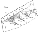
- FIG. 4 shows a second embodiment of the device according to the invention.
- This has a plurality of laser diodes 20 to 29, whose laser diode beams S0 to S9 are imaged on imaging plates 30 to 39 on the phosphor plate 15.
- one of the imaging optics is assigned to one of the laser diodes.
- the imaging optics can, for example For simplicity, be realized by means of cylindrical lenses.
- each laser diode 20 to 29 is used to excite multiple points of the phosphor plate.
- the imaging optics 30 to 39 assigned to the respective laser diode 20 to 29 expands the respective laser diode beam S1 to S9 in the propagation direction B of the line to be excited.
- FIG. 4 shows a line 40 excited by the expanded laser diode beams S0 to S9
- FIG. 4 Representing the radiation fields of all the laser diodes 20 to 29, a first radiation field 41, which is generated by the first laser diode 20 by means of the imaging optics 30 assigned to this first laser diode 20.
- the imaging optics 30 expands the laser diode beam S1 of the laser diode 20 in the propagation direction B of the line 40.
- a boundary of the first radiation field 41 therefore runs on the line 40 from a first point W to a third point Y.
- the laser diode 20 of the laser diode 20, which is expanded by the imaging optical system 30, is also rotated in the direction A perpendicular to the laser by the imaging optical system 30
- Propagation direction B of the line runs and the feed direction of the read head according to the invention for scanning the phosphor plate 15 corresponds focused. It is therefore ensured that only points on the line 40 to be excited by the first radiation field 41 are excited to shine. These points are between the first point W and the third point Y.
- the FIG. 4 also shows representatively a second radiation field 42, which is generated by a second imaging optical unit 31 by conditioning and focusing of a further laser diode beam S1, which originates from a further laser diode 21.
- This further laser diode beam S1 is likewise widened in the propagation direction B of the line 40 by the imaging optics 31 and focused in the feed direction A of the read head.
- the second radiation field 42 therefore stimulates those points of the line 40 which lie between a second point X and a fourth point Z.
- the second point X lies exactly in the middle of the first point W and the third point Y.
- the uniform arrangement of the individual laser diodes 20 to 29 and their associated imaging optics 30 to 39 ensures that each point to be stimulated line 40 is excited by the expanded and focused laser diode beams of two laser diodes. In this way, it is advantageously possible to increase the reliability of this radiation source, since even if one of the laser diodes 20 to 29, the excitation of all points of the line 40 to be stimulated is guaranteed.
- the intensity of the exciting radiation is reduced in case of failure of one of the laser diodes 20 to 29 in the respective falling area, however, this failure can be detected, so that the data processing device, the processing of the digital image data after converting the light detected by the receiving means into electrical Signals that can correct by the failure of faulty digital image data.
- the embodiment of FIG. 4 it is also possible to superimpose more than two laser diode beams on each one point of the line to be excited. As a result, the reliability can be further increased. Furthermore, the number of laser diodes of the radiation source can be changed. It is not limited to the number of ten laser diodes described in this embodiment.
- LEDs LEDs
- LEDs can advantageously also be used in line form.
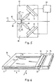
- FIG. 5 shows a third embodiment of the device according to the invention.
- the phosphor plate 15 is provided on its upper side 65 with a first coating which is indistinguishable from a second coating which is applied to the underside 66 of the phosphor plate 15.
- the top 65 and bottom 66 coatings of the phosphor plate 15 have different sensitivities to one another. As a result, X-rayed objects, which have strongly different contrast differences from each other, such as bones or soft tissues, can be reproduced with the same phosphor plate with very good quality.
- the inventive device according to the FIG. 5 has two read heads 10 and 60 for reading the phosphor plate 15.
- the two read heads 10 and 60 correspond in their construction to that of the read head 10, as already described above with reference to the first embodiment according to the FIGS. 1 and 2 has been described.
- the reading heads 10 and 60 therefore both each have a laser diode array 11 or 61 for exciting the dots of the phosphor plate 15.
- the electrical signals generated by the two CCD lines 12 and 62, which contain an image of the image information stored in the X-ray plate 15, are fed to a common data processing device 63.
- This data processing device 63 controls the operation of the two read heads 10 and 60. It can, for example, specify whether one of the two read heads 10 or 60 or both together should read the image information contained in the phosphor plate 15.
- the electrical signals transmitted by the two CCD lines 12 and 62 are combined in the data processing device 63 to form an overall image. The two signals can be weighted differently.
- the possible bilateral readout of the phosphor plate 15 a further improvement in the reproduction of the read-out image information can be achieved. This is particularly because more information stored in the phosphor plate can be read out.
- the scattering of the excitation radiation which is formed when the excitation radiation penetrates into the phosphor plate 15 coated on both sides, is kept small in comparison to a single read head which is attached to one of the sides of the phosphor plate 15 and reads the image information from the phosphor plate coated on both sides become.
- the blurring of the read-out image information due to scattered radiation can be substantially reduced.
- the other radiation sources described above can be used to excite the individual points of the phosphor plate 15.
- FIG. 6 shows an embodiment of an X-ray cassette 70 according to the invention, which has a device according to the invention for reading from an information stored in a phosphor carrier information.
- a device according to the invention is in the present embodiment, the reading head 10, which previously with reference to the first embodiment below Figures 1 and 2 has been described.
- the X-ray cassette 70 according to the invention also has the phosphor plate 15, in which the information can be stored, which is to be read by the reading head 10.
- guide rods 71 and 72 are mounted, which serve the drive and the guide of the read head 10.
- the reading head 10 can advantageously be driven by a linear motor 73, so that it can be guided line by line across the phosphor plate 15 along its feed direction A.
- a control device 75 is provided in the X-ray cassette.
- the two guide rods 71 and 72 serve here as reaction parts For the linear motor 73. Due to the use of the linear motor 73 for driving the reading head 10 can be dispensed with a complex, inaccuracies generating power transmission from a conventional electric motor with a rotating shaft on the read head 10.
- an erasing lamp 74 is mounted, which can also be guided by the linear motor 73 via the phosphor plate 15 in order to erase an image information stored therein.
- the read head 10 and the erase lamp 74 are moved by the same linear motor 73 via the phosphor plate 15.
- Such an X-ray cassette according to the invention can be inserted directly into an X-ray table, so that removal of the X-ray cassette for reading the image information stored therein is not necessary.
- the X-ray cassette 70 has interfaces via which the digital data generated by the reading head 10 can be forwarded to a monitor or a printer.
- the X-ray cassette can be made with very small dimensions. It is possible to limit the thickness of the X-ray cassette to approx. 45 mm, so that it can be inserted into conventional X-ray equipment already in use.
Landscapes
- Molecular Biology (AREA)
- Spectroscopy & Molecular Physics (AREA)
- Signal Processing (AREA)
- Physics & Mathematics (AREA)
- Health & Medical Sciences (AREA)
- Life Sciences & Earth Sciences (AREA)
- Multimedia (AREA)
- General Physics & Mathematics (AREA)
- Engineering & Computer Science (AREA)
- High Energy & Nuclear Physics (AREA)
- Facsimile Scanning Arrangements (AREA)
- Conversion Of X-Rays Into Visible Images (AREA)
- Radiography Using Non-Light Waves (AREA)
- Image Input (AREA)
- Facsimile Heads (AREA)
- Analysing Materials By The Use Of Radiation (AREA)
Applications Claiming Priority (2)
| Application Number | Priority Date | Filing Date | Title |
|---|---|---|---|
| DE19752925A DE19752925C2 (de) | 1997-11-28 | 1997-11-28 | Vorrichtung zum Auslesen von einer in einem Phosphorträger abgespeicherten Information und Röntgenkassette |
| EP98963507A EP1034443B1 (de) | 1997-11-28 | 1998-11-24 | Vorrichtung zum auslesen von einer in einem phosphorträger abgespeicherten information und röntgenkassette |
Related Parent Applications (2)
| Application Number | Title | Priority Date | Filing Date |
|---|---|---|---|
| EP98963507.3 Division | 1998-11-24 | ||
| EP98963507A Division EP1034443B1 (de) | 1997-11-28 | 1998-11-24 | Vorrichtung zum auslesen von einer in einem phosphorträger abgespeicherten information und röntgenkassette |
Publications (3)
| Publication Number | Publication Date |
|---|---|
| EP1424569A2 EP1424569A2 (de) | 2004-06-02 |
| EP1424569A3 EP1424569A3 (de) | 2006-05-31 |
| EP1424569B1 true EP1424569B1 (de) | 2010-08-18 |
Family
ID=7850186
Family Applications (2)
| Application Number | Title | Priority Date | Filing Date |
|---|---|---|---|
| EP03102259A Expired - Lifetime EP1424569B1 (de) | 1997-11-28 | 1998-11-24 | Vorrichtung zum Auslesen von einer in einem Phosphorträger abgespeicherten Information und Röntgenkassette |
| EP98963507A Expired - Lifetime EP1034443B1 (de) | 1997-11-28 | 1998-11-24 | Vorrichtung zum auslesen von einer in einem phosphorträger abgespeicherten information und röntgenkassette |
Family Applications After (1)
| Application Number | Title | Priority Date | Filing Date |
|---|---|---|---|
| EP98963507A Expired - Lifetime EP1034443B1 (de) | 1997-11-28 | 1998-11-24 | Vorrichtung zum auslesen von einer in einem phosphorträger abgespeicherten information und röntgenkassette |
Country Status (7)
| Country | Link |
|---|---|
| US (1) | US6373074B1 (enExample) |
| EP (2) | EP1424569B1 (enExample) |
| JP (1) | JP4422892B2 (enExample) |
| AT (1) | ATE478352T1 (enExample) |
| DE (3) | DE19752925C2 (enExample) |
| ES (1) | ES2207022T3 (enExample) |
| WO (1) | WO1999028765A1 (enExample) |
Families Citing this family (47)
| Publication number | Priority date | Publication date | Assignee | Title |
|---|---|---|---|---|
| DE19922345B4 (de) | 1999-05-14 | 2005-07-28 | Siemens Ag | Vorrichtung zur Auslesung einer Speicherleuchtstoffplatte |
| DE19937416C2 (de) * | 1999-08-07 | 2002-11-14 | Agfa Gevaert Ag | Vorrichtung zum Auslesen von in einer Speicherschicht abgespeicherten Informationen |
| DE60013738T2 (de) * | 1999-11-23 | 2005-09-29 | Agfa-Gevaert | Leuchtstoffträger mit verbessertem Leuchtwirkungsgrad |
| DE19962775C1 (de) * | 1999-12-23 | 2001-03-15 | Agfa Gevaert Ag | Vorrichtung zum Auslesen von in einer Speicherschicht abgespeicherten Informationen und Röntgenkassette |
| US7186997B2 (en) | 1999-12-23 | 2007-03-06 | Agfa-Gevaert Healthcare Gmbh | Device and method for reading out information stored in a storage layer, and x-ray cartridge |
| DE19964445B4 (de) * | 1999-12-23 | 2007-10-04 | Agfa-Gevaert Healthcare Gmbh | Vorrichtung und Verfahren zum Auslesen von in einer Speicherschicht abgespeicherten Informationen |
| DE19962773A1 (de) | 1999-12-23 | 2001-07-26 | Agfa Gevaert Ag | Vorrichtung zum Auslesen von in einer Speicherschicht abgespeicherten Informationen sowie Röntgenkassette und Röntgentisch |
| EP1136842A3 (en) * | 2000-03-15 | 2002-12-04 | Fuji Photo Film Co., Ltd. | Radiation image read-out apparatus |
| JP3999445B2 (ja) | 2000-06-29 | 2007-10-31 | 富士フイルム株式会社 | 放射線画像情報読取方法および装置 |
| US7091511B2 (en) * | 2000-08-28 | 2006-08-15 | Fuji Photo Film Co., Ltd. | Radiation image read-out method and apparatus |
| JP2002148735A (ja) * | 2000-11-08 | 2002-05-22 | Fuji Photo Film Co Ltd | 放射線画像情報記録読取装置 |
| JP2002148743A (ja) * | 2000-11-08 | 2002-05-22 | Fuji Photo Film Co Ltd | 蓄積性蛍光体シート用カセッテ並びに放射線画像撮影装置、撮影情報登録装置および放射線画像情報読取装置 |
| JP2002168787A (ja) * | 2000-12-04 | 2002-06-14 | Fuji Photo Film Co Ltd | 画像読み取り方法および装置 |
| US6800870B2 (en) | 2000-12-20 | 2004-10-05 | Michel Sayag | Light stimulating and collecting methods and apparatus for storage-phosphor image plates |
| US6784448B2 (en) * | 2001-02-27 | 2004-08-31 | Fuji Photo Film Co., Ltd. | Method for reading radiation image from stimulable phosphor sheet |
| EP1319963B1 (de) | 2001-12-17 | 2008-02-20 | Agfa-Gevaert HealthCare GmbH | Vorrichtung und Verfahren zum Auslesen von in einem Speicherleuchtstoff abgespeicherten Informationen |
| EP1378765B1 (de) * | 2002-07-02 | 2010-02-24 | Agfa-Gevaert HealthCare GmbH | Vorrichtung und Verfahren zum Auslesen von in einer Speicherschicht abgespeicherter Information |
| CN100398327C (zh) * | 2002-10-10 | 2008-07-02 | 西铁城控股株式会社 | 曝光装置和用于制造曝光装置的方法 |
| DE10393556B4 (de) * | 2002-12-20 | 2009-01-02 | Agfa-Gevaert Healthcare Gmbh | Scanvorrichtung zum Erfassen einer Bildinformation |
| EP1431777A1 (de) * | 2002-12-20 | 2004-06-23 | Agfa-Gevaert AG | Wandmontierbare Scanvorrichtung zum Erfassen einer Bildinformation |
| DE50303589D1 (de) * | 2003-08-12 | 2006-07-06 | Agfa Gevaert Healthcare Gmbh | Verfahren zum Auslesen von in einer stimulierbaren Phosphorschicht gespeicherten Informationen |
| JP2005072448A (ja) * | 2003-08-27 | 2005-03-17 | Fuji Photo Film Co Ltd | 半導体レーザ装置および放射線画像情報読取装置 |
| US20050051738A1 (en) * | 2003-09-08 | 2005-03-10 | Edgar Alzner | Process and apparatus for retrieving information projected image-wise on a photo-stimulable phosphor imaging substrate |
| US20090256084A1 (en) * | 2003-09-05 | 2009-10-15 | Edgar Alzner | Process and apparatus for retrieving information projected image-wise on a photo-stimulable phosphor imaging substrate |
| US7126147B2 (en) * | 2003-11-20 | 2006-10-24 | Eastman Kodak Company | Storage phosphor readout system using resonant microcavity converter |
| US7071483B2 (en) * | 2003-12-31 | 2006-07-04 | Eastman Kodak Company | Method and system for a multi-axis scanning module |
| US7480082B2 (en) * | 2004-03-31 | 2009-01-20 | Carestream Health, Inc. | Radiation image scanning apparatus and method |
| EP1594086B1 (de) * | 2004-05-04 | 2007-09-12 | Agfa-Gevaert HealthCare GmbH | Verfahren zur Erfassung und Darstellung eines in einer Phosphorschicht gespeicherten Röntgenbildes |
| EP1598779B1 (en) * | 2004-05-18 | 2013-07-24 | Agfa HealthCare NV | Suppression of periodic variations in a digital signal. |
| EP1598833B1 (de) * | 2004-05-21 | 2011-03-02 | Agfa-Gevaert HealthCare GmbH | Speicherleuchtstoffplatte zur Speicherung von Röntgeninformation |
| ATE405863T1 (de) | 2004-09-22 | 2008-09-15 | Agfa Gevaert Healthcare Gmbh | Vorrichtung zum auslesen von in einer speicherleuchtstoffplatte gespeicherten röntgeninformation |
| DE502004010009D1 (de) * | 2004-12-20 | 2009-10-15 | Agfa Gevaert Healthcare Gmbh | System und Verfahren zum Auslesen von in einer Speicherleuchtstoffschicht gespeicherter Röntgeninformation |
| DE102005038999A1 (de) * | 2005-08-16 | 2007-03-01 | Schott Ag | Strahlformungseinrichtung eines optischen Systems, insbesondere eines optischen Signalaufnehmers und optisches System, insbesondere optischer Signalaufnehmer mit Strahlformungseinrichtung |
| US7619786B2 (en) * | 2005-03-24 | 2009-11-17 | Carestream Health, Inc. | Linear illumination apparatus and method |
| US20060214123A1 (en) * | 2005-03-24 | 2006-09-28 | Eastman Kodak Company | Linear illumination using cylindrical elliptical reflective surface |
| JP4638775B2 (ja) * | 2005-07-01 | 2011-02-23 | シスメックス株式会社 | 分析装置 |
| US7244955B2 (en) * | 2005-12-15 | 2007-07-17 | General Electric Company | Computed radiography systems and methods of use |
| US7576349B2 (en) | 2005-12-23 | 2009-08-18 | Carestream Health, Inc. | Radiation image readout apparatus |
| EP1895364B1 (de) * | 2006-08-29 | 2014-03-12 | Agfa HealthCare NV | Vorrichtung und Verfahren zum Auslesen von Speicherleuchtstoffplatten |
| DE502006007435D1 (de) * | 2006-08-29 | 2010-08-26 | Agfa Healthcare Nv | Verfahren und Vorrichtung zum Bearbeiten von Informationsträgern, insbesondere zum Auslesen von Speicherleuchtstoffplatten |
| EP1895327B1 (de) * | 2006-08-31 | 2009-11-11 | Agfa HealthCare NV | Löschen einer Speicherleuchtstoffschicht |
| DE502006006583D1 (de) * | 2006-08-31 | 2010-05-12 | Agfa Healthcare Nv | Löschen einer Speicherleuchtstoffschicht |
| ATE474238T1 (de) * | 2006-08-31 | 2010-07-15 | Agfa Healthcare Nv | Vorrichtung zum löschen einer speicherleuchtstoffschicht |
| DE102007045799B4 (de) * | 2007-09-25 | 2016-02-18 | Fraunhofer-Gesellschaft zur Förderung der angewandten Forschung e.V. | Modularer bildgebender Röntgengroßdetektor und Röntgendetektionsverfahren |
| EP2290404B1 (de) | 2009-08-31 | 2012-08-29 | Agfa HealthCare NV | Verfahren und Vorrichtung zum Auslesen und Löschen von in Speicherleuchstoffschichten gespeicherten Röntgeninformationen |
| WO2013089817A1 (en) | 2011-12-16 | 2013-06-20 | Li-Cor, Inc. | Luminescence imaging scanner |
| US10458931B1 (en) * | 2016-06-17 | 2019-10-29 | Leidos, Inc. | Contact imaging sensor head for computed radiography |
Family Cites Families (15)
| Publication number | Priority date | Publication date | Assignee | Title |
|---|---|---|---|---|
| JPS60111568A (ja) * | 1983-11-21 | 1985-06-18 | Fuji Photo Film Co Ltd | 放射線画像情報読取装置 |
| JPH0626415B2 (ja) * | 1984-05-09 | 1994-04-06 | 富士写真フイルム株式会社 | 放射線画像情報読取装置 |
| US4737641A (en) * | 1985-08-16 | 1988-04-12 | Siemens Aktiengesellschaft | Apparatus for producing x-ray images by computer radiography |
| EP0482676B1 (en) * | 1985-10-18 | 1996-02-28 | Fuji Photo Film Co., Ltd. | Radiation image storing panel and method of moving the same in an image recording and read-out apparatus |
| JPS62161265A (ja) * | 1985-12-27 | 1987-07-17 | Fuji Photo Film Co Ltd | 放射線画像情報読取装置 |
| US5038037A (en) * | 1987-12-29 | 1991-08-06 | Fuji Photo Film Co., Ltd. | Radiation image recording and read-out apparatus |
| JP2527361B2 (ja) * | 1988-03-19 | 1996-08-21 | 富士写真フイルム株式会社 | 放射線画像読取再生装置 |
| US5864146A (en) * | 1996-11-13 | 1999-01-26 | University Of Massachusetts Medical Center | System for quantitative radiographic imaging |
| JP2670632B2 (ja) * | 1990-01-12 | 1997-10-29 | 富士写真フイルム株式会社 | 光走査装置 |
| IT1249543B (it) * | 1990-10-05 | 1995-02-28 | Minnesota Mining & Mfg | Metodo ed apparecchiatura per la lettura di un pannello di fosforo fotostimolabile |
| DE19506798C2 (de) * | 1995-02-27 | 1999-10-21 | Siemens Ag | Vorrichtung zur Digitalisierung von röntgenologischen Speicherfolienbildern |
| DE19506809C2 (de) * | 1995-02-27 | 1999-09-30 | Siemens Ag | Vorrichtung zur Digitalisierung von Röntgenbildern |
| JP3394375B2 (ja) | 1995-12-01 | 2003-04-07 | 富士写真フイルム株式会社 | 放射線画像読取装置 |
| US5864362A (en) * | 1996-08-27 | 1999-01-26 | Hewlett-Packard Company | High speed scanner for reading latent images in storage phosphors |
| EP0859244B1 (en) * | 1997-01-31 | 2002-12-11 | Agfa-Gevaert | Method for obtaining a radiation image using CCD sensors |
-
1997
- 1997-11-28 DE DE19752925A patent/DE19752925C2/de not_active Expired - Fee Related
-
1998
- 1998-11-24 DE DE59809514T patent/DE59809514D1/de not_active Expired - Lifetime
- 1998-11-24 EP EP03102259A patent/EP1424569B1/de not_active Expired - Lifetime
- 1998-11-24 AT AT03102259T patent/ATE478352T1/de not_active IP Right Cessation
- 1998-11-24 ES ES98963507T patent/ES2207022T3/es not_active Expired - Lifetime
- 1998-11-24 JP JP2000523567A patent/JP4422892B2/ja not_active Expired - Fee Related
- 1998-11-24 EP EP98963507A patent/EP1034443B1/de not_active Expired - Lifetime
- 1998-11-24 WO PCT/EP1998/007570 patent/WO1999028765A1/de not_active Ceased
- 1998-11-24 US US09/554,974 patent/US6373074B1/en not_active Expired - Fee Related
- 1998-11-24 DE DE59814463T patent/DE59814463D1/de not_active Expired - Lifetime
Also Published As
| Publication number | Publication date |
|---|---|
| ATE478352T1 (de) | 2010-09-15 |
| DE59809514D1 (de) | 2003-10-09 |
| EP1424569A2 (de) | 2004-06-02 |
| EP1034443B1 (de) | 2003-09-03 |
| DE19752925C2 (de) | 2003-11-27 |
| JP2001525549A (ja) | 2001-12-11 |
| DE19752925A1 (de) | 1999-06-24 |
| ES2207022T3 (es) | 2004-05-16 |
| EP1424569A3 (de) | 2006-05-31 |
| US6373074B1 (en) | 2002-04-16 |
| WO1999028765A1 (de) | 1999-06-10 |
| EP1034443A1 (de) | 2000-09-13 |
| JP4422892B2 (ja) | 2010-02-24 |
| DE59814463D1 (de) | 2010-09-30 |
Similar Documents
| Publication | Publication Date | Title |
|---|---|---|
| EP1424569B1 (de) | Vorrichtung zum Auslesen von einer in einem Phosphorträger abgespeicherten Information und Röntgenkassette | |
| DE19859747C1 (de) | Vorrichtung und Verfahren zum Auslesen von in einer Phosphorschicht abgespeicherten Informationen | |
| DE69616030T2 (de) | Röntgenstrahluntersuchungsvorrichtung eine bildaufnahmematrix mit korrektureinheit enthaltend | |
| EP1111407A2 (de) | Vorrichtung zum Auslesen von in einer Speicherschicht abgespeicherten Informationen und Röntgenkassette | |
| EP1691216B1 (de) | Radiographiesystem und Verfahren zur Aufzeichnung von Röntgenaufnahmen in Speicherleuchtstoffschichten | |
| EP0358796A1 (de) | Röntgendiagnostikeinrichtung mit einem Speicherleucht- schirm | |
| EP1542051B1 (de) | Verfahren und Vorrichtung zum Trennen unterschiedlicher Emissionswellenlängen in einem Scanmikroskop | |
| EP1691217B1 (de) | Auslesevorrichtung und Verfahren zum Auslesen von in Speicherleuchtstoffschichten gespeicherten Röntgenaufnahmen | |
| DE69809976T2 (de) | Verfahren zur Erzeugung eines strahlungsbildes mit CCD-Sensors | |
| DE69834954T2 (de) | Strahlungsbildlesegerät | |
| EP1691215A1 (de) | Auslesevorrichtung und Verfahren zum Auslesen von in Speicherleuchtstoffschichten gespeicherten Röntgenaufnahmen | |
| EP1494067B1 (de) | System mit einem Scanner und einer Speicherschicht sowie Speicherschicht zum Speichern von Röntgeninformationen | |
| EP1507151B1 (de) | Verfahren zum Auslesen von in einer stimulierbaren Phosphorschicht gespeicherten Informationen | |
| DE3637023C2 (enExample) | ||
| DE60023988T2 (de) | Verfahren und Vorrichtung zum Auslesen von Strahlungsbildern | |
| EP1621899B1 (de) | Verfahren zum Auslesen von in einer Phosphorschicht gespeicherten Informationen | |
| EP3274767B1 (de) | Speicherfolienscanner | |
| EP1895324B1 (de) | Verfahren und Vorrichtung zum Auslesen von in einer Speicherleuchtstoffplatte gespeicherten Röntgeninformationen | |
| EP0191322A1 (de) | Anordnung zum Herstellen von Röntgenbildern durch Computer-Radiographie | |
| EP1612583B1 (de) | Vorrichtung und Verfahren zum Auslesen von in einer Speicherphosphorschicht gespeicherten Röntgeninformationen | |
| EP0961930A1 (de) | Lichtabtastvorrichtung | |
| EP1612582B1 (de) | Verfahren zum Auslesen von in einer Speicherphosphorschicht gespeicherter Röntgeninformationen | |
| EP2290404A1 (de) | Verfahren und Vorrichtung zum Auslesen und Löschen von in Speicherleuchstoffschichten gespeicherten Röntgeninformationen | |
| DE3742920C2 (enExample) | ||
| EP2793053A1 (de) | Verfahren und Vorrichtungen zum Auslesen von in einer Speicherleuchtstoffschicht gespeicherten Röntgeninformationen |
Legal Events
| Date | Code | Title | Description |
|---|---|---|---|
| PUAI | Public reference made under article 153(3) epc to a published international application that has entered the european phase |
Free format text: ORIGINAL CODE: 0009012 |
|
| AC | Divisional application: reference to earlier application |
Ref document number: 1034443 Country of ref document: EP Kind code of ref document: P |
|
| AK | Designated contracting states |
Kind code of ref document: A2 Designated state(s): AT BE CH CY DE DK ES FI FR GB GR IE IT LI LU MC NL PT SE TR |
|
| RAP1 | Party data changed (applicant data changed or rights of an application transferred) |
Owner name: AGFA-GEVAERT HEALTHCARE GMBH |
|
| RIC1 | Information provided on ipc code assigned before grant |
Ipc: G01T 1/29 20060101AFI20040413BHEP Ipc: H04N 1/028 20060101ALI20060120BHEP |
|
| PUAL | Search report despatched |
Free format text: ORIGINAL CODE: 0009013 |
|
| AK | Designated contracting states |
Kind code of ref document: A3 Designated state(s): AT BE CH CY DE DK ES FI FR GB GR IE IT LI LU MC NL PT SE TR |
|
| 17P | Request for examination filed |
Effective date: 20061130 |
|
| AKX | Designation fees paid |
Designated state(s): AT BE CH CY DE DK ES FI FR GB GR IE IT LI LU MC NL PT SE |
|
| 17Q | First examination report despatched |
Effective date: 20070129 |
|
| RAP1 | Party data changed (applicant data changed or rights of an application transferred) |
Owner name: AGFA-GEVAERT HEALTHCARE GMBH |
|
| GRAP | Despatch of communication of intention to grant a patent |
Free format text: ORIGINAL CODE: EPIDOSNIGR1 |
|
| GRAS | Grant fee paid |
Free format text: ORIGINAL CODE: EPIDOSNIGR3 |
|
| GRAA | (expected) grant |
Free format text: ORIGINAL CODE: 0009210 |
|
| AC | Divisional application: reference to earlier application |
Ref document number: 1034443 Country of ref document: EP Kind code of ref document: P |
|
| AK | Designated contracting states |
Kind code of ref document: B1 Designated state(s): AT BE CH CY DE DK ES FI FR GB GR IE IT LI LU MC NL PT SE |
|
| REG | Reference to a national code |
Ref country code: GB Ref legal event code: FG4D Free format text: NOT ENGLISH |
|
| REG | Reference to a national code |
Ref country code: CH Ref legal event code: EP |
|
| REG | Reference to a national code |
Ref country code: IE Ref legal event code: FG4D Free format text: LANGUAGE OF EP DOCUMENT: GERMAN |
|
| REF | Corresponds to: |
Ref document number: 59814463 Country of ref document: DE Date of ref document: 20100930 Kind code of ref document: P |
|
| REG | Reference to a national code |
Ref country code: NL Ref legal event code: VDEP Effective date: 20100818 |
|
| PG25 | Lapsed in a contracting state [announced via postgrant information from national office to epo] |
Ref country code: FI Free format text: LAPSE BECAUSE OF FAILURE TO SUBMIT A TRANSLATION OF THE DESCRIPTION OR TO PAY THE FEE WITHIN THE PRESCRIBED TIME-LIMIT Effective date: 20100818 |
|
| PG25 | Lapsed in a contracting state [announced via postgrant information from national office to epo] |
Ref country code: CY Free format text: LAPSE BECAUSE OF FAILURE TO SUBMIT A TRANSLATION OF THE DESCRIPTION OR TO PAY THE FEE WITHIN THE PRESCRIBED TIME-LIMIT Effective date: 20100818 Ref country code: PT Free format text: LAPSE BECAUSE OF FAILURE TO SUBMIT A TRANSLATION OF THE DESCRIPTION OR TO PAY THE FEE WITHIN THE PRESCRIBED TIME-LIMIT Effective date: 20101220 |
|
| REG | Reference to a national code |
Ref country code: IE Ref legal event code: FD4D |
|
| PG25 | Lapsed in a contracting state [announced via postgrant information from national office to epo] |
Ref country code: GR Free format text: LAPSE BECAUSE OF FAILURE TO SUBMIT A TRANSLATION OF THE DESCRIPTION OR TO PAY THE FEE WITHIN THE PRESCRIBED TIME-LIMIT Effective date: 20101119 Ref country code: NL Free format text: LAPSE BECAUSE OF FAILURE TO SUBMIT A TRANSLATION OF THE DESCRIPTION OR TO PAY THE FEE WITHIN THE PRESCRIBED TIME-LIMIT Effective date: 20100818 Ref country code: SE Free format text: LAPSE BECAUSE OF FAILURE TO SUBMIT A TRANSLATION OF THE DESCRIPTION OR TO PAY THE FEE WITHIN THE PRESCRIBED TIME-LIMIT Effective date: 20100818 |
|
| PGFP | Annual fee paid to national office [announced via postgrant information from national office to epo] |
Ref country code: GB Payment date: 20101021 Year of fee payment: 13 |
|
| PG25 | Lapsed in a contracting state [announced via postgrant information from national office to epo] |
Ref country code: IE Free format text: LAPSE BECAUSE OF FAILURE TO SUBMIT A TRANSLATION OF THE DESCRIPTION OR TO PAY THE FEE WITHIN THE PRESCRIBED TIME-LIMIT Effective date: 20100818 Ref country code: DK Free format text: LAPSE BECAUSE OF FAILURE TO SUBMIT A TRANSLATION OF THE DESCRIPTION OR TO PAY THE FEE WITHIN THE PRESCRIBED TIME-LIMIT Effective date: 20100818 |
|
| BERE | Be: lapsed |
Owner name: AGFA-GEVAERT HEALTHCARE G.M.B.H. Effective date: 20101130 |
|
| PG25 | Lapsed in a contracting state [announced via postgrant information from national office to epo] |
Ref country code: IT Free format text: LAPSE BECAUSE OF FAILURE TO SUBMIT A TRANSLATION OF THE DESCRIPTION OR TO PAY THE FEE WITHIN THE PRESCRIBED TIME-LIMIT Effective date: 20100818 |
|
| PLBE | No opposition filed within time limit |
Free format text: ORIGINAL CODE: 0009261 |
|
| STAA | Information on the status of an ep patent application or granted ep patent |
Free format text: STATUS: NO OPPOSITION FILED WITHIN TIME LIMIT |
|
| PG25 | Lapsed in a contracting state [announced via postgrant information from national office to epo] |
Ref country code: ES Free format text: LAPSE BECAUSE OF FAILURE TO SUBMIT A TRANSLATION OF THE DESCRIPTION OR TO PAY THE FEE WITHIN THE PRESCRIBED TIME-LIMIT Effective date: 20101129 |
|
| REG | Reference to a national code |
Ref country code: CH Ref legal event code: PL |
|
| 26N | No opposition filed |
Effective date: 20110519 |
|
| PG25 | Lapsed in a contracting state [announced via postgrant information from national office to epo] |
Ref country code: LI Free format text: LAPSE BECAUSE OF NON-PAYMENT OF DUE FEES Effective date: 20101130 Ref country code: CH Free format text: LAPSE BECAUSE OF NON-PAYMENT OF DUE FEES Effective date: 20101130 |
|
| PG25 | Lapsed in a contracting state [announced via postgrant information from national office to epo] |
Ref country code: BE Free format text: LAPSE BECAUSE OF NON-PAYMENT OF DUE FEES Effective date: 20101130 |
|
| REG | Reference to a national code |
Ref country code: DE Ref legal event code: R097 Ref document number: 59814463 Country of ref document: DE Effective date: 20110519 |
|
| PGFP | Annual fee paid to national office [announced via postgrant information from national office to epo] |
Ref country code: FR Payment date: 20111018 Year of fee payment: 14 |
|
| REG | Reference to a national code |
Ref country code: AT Ref legal event code: MM01 Ref document number: 478352 Country of ref document: AT Kind code of ref document: T Effective date: 20101124 |
|
| PG25 | Lapsed in a contracting state [announced via postgrant information from national office to epo] |
Ref country code: AT Free format text: LAPSE BECAUSE OF NON-PAYMENT OF DUE FEES Effective date: 20101124 |
|
| REG | Reference to a national code |
Ref country code: DE Ref legal event code: R084 Ref document number: 59814463 Country of ref document: DE Effective date: 20120412 |
|
| PG25 | Lapsed in a contracting state [announced via postgrant information from national office to epo] |
Ref country code: LU Free format text: LAPSE BECAUSE OF NON-PAYMENT OF DUE FEES Effective date: 20101124 |
|
| PG25 | Lapsed in a contracting state [announced via postgrant information from national office to epo] |
Ref country code: MC Free format text: LAPSE BECAUSE OF NON-PAYMENT OF DUE FEES Effective date: 20100818 |
|
| GBPC | Gb: european patent ceased through non-payment of renewal fee |
Effective date: 20121124 |
|
| REG | Reference to a national code |
Ref country code: FR Ref legal event code: ST Effective date: 20130731 |
|
| PG25 | Lapsed in a contracting state [announced via postgrant information from national office to epo] |
Ref country code: FR Free format text: LAPSE BECAUSE OF NON-PAYMENT OF DUE FEES Effective date: 20121130 Ref country code: GB Free format text: LAPSE BECAUSE OF NON-PAYMENT OF DUE FEES Effective date: 20121124 |
|
| PGFP | Annual fee paid to national office [announced via postgrant information from national office to epo] |
Ref country code: DE Payment date: 20140908 Year of fee payment: 17 |
|
| REG | Reference to a national code |
Ref country code: DE Ref legal event code: R119 Ref document number: 59814463 Country of ref document: DE |
|
| PG25 | Lapsed in a contracting state [announced via postgrant information from national office to epo] |
Ref country code: DE Free format text: LAPSE BECAUSE OF NON-PAYMENT OF DUE FEES Effective date: 20160601 |