EP1424495A2 - Vane pump - Google Patents
Vane pump Download PDFInfo
- Publication number
- EP1424495A2 EP1424495A2 EP04004782A EP04004782A EP1424495A2 EP 1424495 A2 EP1424495 A2 EP 1424495A2 EP 04004782 A EP04004782 A EP 04004782A EP 04004782 A EP04004782 A EP 04004782A EP 1424495 A2 EP1424495 A2 EP 1424495A2
- Authority
- EP
- European Patent Office
- Prior art keywords
- rotor
- pump
- plastic
- wing
- metal
- Prior art date
- Legal status (The legal status is an assumption and is not a legal conclusion. Google has not performed a legal analysis and makes no representation as to the accuracy of the status listed.)
- Withdrawn
Links
- 238000006073 displacement reaction Methods 0.000 claims abstract description 20
- 239000000919 ceramic Substances 0.000 claims abstract description 12
- 239000004033 plastic Substances 0.000 claims abstract description 9
- 239000002184 metal Substances 0.000 claims abstract description 6
- 238000007789 sealing Methods 0.000 claims description 24
- 239000004696 Poly ether ether ketone Substances 0.000 claims description 4
- 239000004734 Polyphenylene sulfide Substances 0.000 claims description 4
- 229920010524 Syndiotactic polystyrene Polymers 0.000 claims description 4
- 229920002530 polyetherether ketone Polymers 0.000 claims description 4
- 229920000069 polyphenylene sulfide Polymers 0.000 claims description 4
- 239000004721 Polyphenylene oxide Substances 0.000 claims description 2
- UCKMPCXJQFINFW-UHFFFAOYSA-N Sulphide Chemical compound [S-2] UCKMPCXJQFINFW-UHFFFAOYSA-N 0.000 claims description 2
- 229920000570 polyether Polymers 0.000 claims description 2
- 150000001875 compounds Chemical class 0.000 claims 1
- 239000002131 composite material Substances 0.000 abstract 1
- 230000002093 peripheral effect Effects 0.000 description 6
- 239000000463 material Substances 0.000 description 5
- 230000006835 compression Effects 0.000 description 3
- 238000007906 compression Methods 0.000 description 3
- 239000012530 fluid Substances 0.000 description 2
- 230000006978 adaptation Effects 0.000 description 1
- 238000010276 construction Methods 0.000 description 1
- 230000003993 interaction Effects 0.000 description 1
- 239000007788 liquid Substances 0.000 description 1
- 238000000034 method Methods 0.000 description 1
- 239000002991 molded plastic Substances 0.000 description 1
- 238000005507 spraying Methods 0.000 description 1
Images


Classifications
-
- F—MECHANICAL ENGINEERING; LIGHTING; HEATING; WEAPONS; BLASTING
- F04—POSITIVE - DISPLACEMENT MACHINES FOR LIQUIDS; PUMPS FOR LIQUIDS OR ELASTIC FLUIDS
- F04C—ROTARY-PISTON, OR OSCILLATING-PISTON, POSITIVE-DISPLACEMENT MACHINES FOR LIQUIDS; ROTARY-PISTON, OR OSCILLATING-PISTON, POSITIVE-DISPLACEMENT PUMPS
- F04C2/00—Rotary-piston machines or pumps
- F04C2/30—Rotary-piston machines or pumps having the characteristics covered by two or more groups F04C2/02, F04C2/08, F04C2/22, F04C2/24 or having the characteristics covered by one of these groups together with some other type of movement between co-operating members
- F04C2/34—Rotary-piston machines or pumps having the characteristics covered by two or more groups F04C2/02, F04C2/08, F04C2/22, F04C2/24 or having the characteristics covered by one of these groups together with some other type of movement between co-operating members having the movement defined in groups F04C2/08 or F04C2/22 and relative reciprocation between the co-operating members
- F04C2/344—Rotary-piston machines or pumps having the characteristics covered by two or more groups F04C2/02, F04C2/08, F04C2/22, F04C2/24 or having the characteristics covered by one of these groups together with some other type of movement between co-operating members having the movement defined in groups F04C2/08 or F04C2/22 and relative reciprocation between the co-operating members with vanes reciprocating with respect to the inner member
- F04C2/3441—Rotary-piston machines or pumps having the characteristics covered by two or more groups F04C2/02, F04C2/08, F04C2/22, F04C2/24 or having the characteristics covered by one of these groups together with some other type of movement between co-operating members having the movement defined in groups F04C2/08 or F04C2/22 and relative reciprocation between the co-operating members with vanes reciprocating with respect to the inner member the inner and outer member being in contact along one line or continuous surface substantially parallel to the axis of rotation
-
- F—MECHANICAL ENGINEERING; LIGHTING; HEATING; WEAPONS; BLASTING
- F01—MACHINES OR ENGINES IN GENERAL; ENGINE PLANTS IN GENERAL; STEAM ENGINES
- F01C—ROTARY-PISTON OR OSCILLATING-PISTON MACHINES OR ENGINES
- F01C21/00—Component parts, details or accessories not provided for in groups F01C1/00 - F01C20/00
- F01C21/08—Rotary pistons
- F01C21/0809—Construction of vanes or vane holders
- F01C21/0881—Construction of vanes or vane holders the vanes consisting of two or more parts
-
- F—MECHANICAL ENGINEERING; LIGHTING; HEATING; WEAPONS; BLASTING
- F04—POSITIVE - DISPLACEMENT MACHINES FOR LIQUIDS; PUMPS FOR LIQUIDS OR ELASTIC FLUIDS
- F04C—ROTARY-PISTON, OR OSCILLATING-PISTON, POSITIVE-DISPLACEMENT MACHINES FOR LIQUIDS; ROTARY-PISTON, OR OSCILLATING-PISTON, POSITIVE-DISPLACEMENT PUMPS
- F04C18/00—Rotary-piston pumps specially adapted for elastic fluids
- F04C18/30—Rotary-piston pumps specially adapted for elastic fluids having the characteristics covered by two or more of groups F04C18/02, F04C18/08, F04C18/22, F04C18/24, F04C18/48, or having the characteristics covered by one of these groups together with some other type of movement between co-operating members
- F04C18/34—Rotary-piston pumps specially adapted for elastic fluids having the characteristics covered by two or more of groups F04C18/02, F04C18/08, F04C18/22, F04C18/24, F04C18/48, or having the characteristics covered by one of these groups together with some other type of movement between co-operating members having the movement defined in group F04C18/08 or F04C18/22 and relative reciprocation between the co-operating members
- F04C18/344—Rotary-piston pumps specially adapted for elastic fluids having the characteristics covered by two or more of groups F04C18/02, F04C18/08, F04C18/22, F04C18/24, F04C18/48, or having the characteristics covered by one of these groups together with some other type of movement between co-operating members having the movement defined in group F04C18/08 or F04C18/22 and relative reciprocation between the co-operating members with vanes reciprocating with respect to the inner member
- F04C18/3441—Rotary-piston pumps specially adapted for elastic fluids having the characteristics covered by two or more of groups F04C18/02, F04C18/08, F04C18/22, F04C18/24, F04C18/48, or having the characteristics covered by one of these groups together with some other type of movement between co-operating members having the movement defined in group F04C18/08 or F04C18/22 and relative reciprocation between the co-operating members with vanes reciprocating with respect to the inner member the inner and outer member being in contact along one line or continuous surface substantially parallel to the axis of rotation
- F04C18/3442—Rotary-piston pumps specially adapted for elastic fluids having the characteristics covered by two or more of groups F04C18/02, F04C18/08, F04C18/22, F04C18/24, F04C18/48, or having the characteristics covered by one of these groups together with some other type of movement between co-operating members having the movement defined in group F04C18/08 or F04C18/22 and relative reciprocation between the co-operating members with vanes reciprocating with respect to the inner member the inner and outer member being in contact along one line or continuous surface substantially parallel to the axis of rotation the surfaces of the inner and outer member, forming the inlet and outlet opening
-
- F—MECHANICAL ENGINEERING; LIGHTING; HEATING; WEAPONS; BLASTING
- F04—POSITIVE - DISPLACEMENT MACHINES FOR LIQUIDS; PUMPS FOR LIQUIDS OR ELASTIC FLUIDS
- F04C—ROTARY-PISTON, OR OSCILLATING-PISTON, POSITIVE-DISPLACEMENT MACHINES FOR LIQUIDS; ROTARY-PISTON, OR OSCILLATING-PISTON, POSITIVE-DISPLACEMENT PUMPS
- F04C2/00—Rotary-piston machines or pumps
- F04C2/30—Rotary-piston machines or pumps having the characteristics covered by two or more groups F04C2/02, F04C2/08, F04C2/22, F04C2/24 or having the characteristics covered by one of these groups together with some other type of movement between co-operating members
- F04C2/34—Rotary-piston machines or pumps having the characteristics covered by two or more groups F04C2/02, F04C2/08, F04C2/22, F04C2/24 or having the characteristics covered by one of these groups together with some other type of movement between co-operating members having the movement defined in groups F04C2/08 or F04C2/22 and relative reciprocation between the co-operating members
- F04C2/344—Rotary-piston machines or pumps having the characteristics covered by two or more groups F04C2/02, F04C2/08, F04C2/22, F04C2/24 or having the characteristics covered by one of these groups together with some other type of movement between co-operating members having the movement defined in groups F04C2/08 or F04C2/22 and relative reciprocation between the co-operating members with vanes reciprocating with respect to the inner member
- F04C2/3441—Rotary-piston machines or pumps having the characteristics covered by two or more groups F04C2/02, F04C2/08, F04C2/22, F04C2/24 or having the characteristics covered by one of these groups together with some other type of movement between co-operating members having the movement defined in groups F04C2/08 or F04C2/22 and relative reciprocation between the co-operating members with vanes reciprocating with respect to the inner member the inner and outer member being in contact along one line or continuous surface substantially parallel to the axis of rotation
- F04C2/3442—Rotary-piston machines or pumps having the characteristics covered by two or more groups F04C2/02, F04C2/08, F04C2/22, F04C2/24 or having the characteristics covered by one of these groups together with some other type of movement between co-operating members having the movement defined in groups F04C2/08 or F04C2/22 and relative reciprocation between the co-operating members with vanes reciprocating with respect to the inner member the inner and outer member being in contact along one line or continuous surface substantially parallel to the axis of rotation the surfaces of the inner and outer member, forming the working space, being surfaces of revolution
Definitions
- the invention relates to a positive displacement pump with the Features of the preamble of claim 1.
- a positive displacement pump is already known from DE 41 07 720 A1, whose the two chambers of the pump housing space separating, guided wing on both Front ends each movable in the longitudinal direction of the wing guided and on the inner peripheral wall of the housing space wearing sealing strip.
- these are in Cross-section T-shaped, the T-beam is convexly curved on the outside in cross section and accordingly the peripheral wall only along a surface line touched.
- the middle ledge is on the front with one in the wing molded longitudinal groove movable in the longitudinal direction of the wing engaged so that the sealing strips when the drive shaft rotates under the action of centrifugal force automatically attach to the inner wall of the housing.
- Positive displacement pumps of this embodiment are therefore suitable e.g. not for the evacuation of a brake booster a motor vehicle, since in this case even small ones Speeds an evacuation must be ensured.
- the invention is therefore based on the object Provide positive displacement pump, which also without problems Motor vehicles can be used.
- the optimal material pairings become.
- the components that are heavily used are made of a harder material, e.g. Metal and / or ceramic manufactured, the components being kinematically strong be claimed, i.e. which often accelerates and decelerates are made of a lighter material.
- connection is a metal-plastic connection, Metal-ceramic connection, metal-plastic-ceramic connection or plastic-ceramic connection.
- the plastic can be a polyether ether ketone (PEEK), Polyether sulfide (PES), syndiotactic polystyrene (SPS) or a polyphenylene sulfide (PPS).
- PEEK polyether ether ketone
- PES Polyether sulfide
- SPS syndiotactic polystyrene
- PPS polyphenylene sulfide
- the positive displacement pump according to FIG. 1 comprises in a known manner Way a pump housing 10, one in its e.g. circular cylindrical housing space 12 eccentrically mounted Pump rotor 16, the drive shaft 14 rotatably is connected in a rotationally fixed manner and radially in this slidably guided rotor blade 18, which at its Wing ends each carries a sealing strip 20 or 22.
- the pump rotor 16 preferably has a hollow cylindrical one Rotor shell 24 in which one along its Inner diameter extending inner wing guide strip 26 is provided, in which the rotor blade 18 is radial is slidably received. 28 denotes inner rotor webs for stiffening the rotor shell.
- the rotor 16 is for Drive shaft 14 as a guide for the wing 18th slotted and plugged onto the shaft 14, inserted or molded.
- the housing space 12 is, for simplicity's sake, not is shown, tightly closed on both ends, the drive shaft 14 the one housing end wall penetrated liquid-tight.
- At the housing space 12 are also an inflow and an outflow line connected to a fluid to be promoted To be able to supply and discharge positive displacement pump.
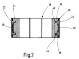
- the sealing strips 20, 22 of the rotor blade 18 are in the Cross section preferably U-shaped and overlap one with their U-legs 30, 32 the wing tips preferably over the entire Wing width molded guide bar 34.
- the sealing strips 20, 22 for In the longitudinal direction of the rotor blade 18 these are preferred with two spaced apart and parallel to each other provided guide pieces 36, 38 equipped to integrally formed the connecting web 40 of their U-legs 30, 32 are and extend parallel to these, their Length is preferably less than that of the U-leg 30, 32.
- the guide pieces 36, 38 each engage in one blind hole-like recess 42 and 44 and so also an exact alignment of the sealing strips 20, 22 transversely to the longitudinal direction of the wing.
- the U-leg connecting web 40 of the sealing strips 20, 22 is preferably designed in cross section so that it on the outside at the same time a sealing edge 46 is defined.
- an energy store preferably in the form a leaf spring 48 is provided, which constantly tries to relevant sealing strip 20 or 22 in the direction of To shift or circumferential inner wall of the housing space 12 to keep in touch with this.
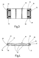
- a compression spring 50 or 52 can be introduced, on which the ledge guide pieces 36, 38 are supported (FIG. 3).
- the rotor blades 18 and the sealing strips 20, 22 are preferably designed as a molded plastic part, the Rotor blades 18 in particular for the purpose of uniform material distribution in the spraying process, for example with three of these in Transverse direction parallel to its flat sides, Flat slot-like recesses 54 is equipped.
- the Pump rotor 16 can also be stored centrally in the housing space 12 if the latter has an oval peripheral shape.
- the positive displacement pump according to FIGS. 5 and 6 comprises one Flange body with a pump housing 61 forming Cylinder cup 62, a pump drive shaft mounted in this 63 with attached rotor 64 and one in one the recess running rotor center, as Whole with 65 marked, two-part wings.
- the sealing strips 66 face the wall of the cylinder pot 62 provided with a concave radius 68 (Fig. 5). Consequently there are two lines of contact at 69 and 70, which in Interaction with the flat wing sections 65 ', 65' ' to seal the chambers in front of and behind the wing 65 serve. Radii 71 are at the ends of the sealing strips 66 and 72 are provided, which ensures optimal resealing is achieved.
- the rotor 64 is towards the drive shaft 63 as a guide for slotted the wing 65 and plugged onto the shaft 63, inserted or molded.
- This change in length is due to the radial mobility of the Wing sections 65 ', 65' 'balanced.
- the adaptation to the variable length in the angle of rotation happens through that Pressing the sealing strips 66 and taking the Wing 65 through the drive shaft 63 through the shaped spring 67 or by a corresponding compression spring, which the Wing sections 65 ', 65' 'apart and with this connected sealing strips 66 to the Pressed on cylinder wall.
Abstract
Description
Die Erfindung betrifft eine Verdrängerpumpe mit den Merkmalen des Oberbegriffs von Anspruch 1.The invention relates to a positive displacement pump with the Features of the preamble of claim 1.
Aus DE 41 07 720 A1 bereits eine Verdrängerpumpe bekannt, deren die beiden Kammern des Pumpengehäuseraumes voneinander trennender, zwangsgeführter Flügel an beiden Stirnenden jeweils eine in Flügellängsrichtung beweglich geführte und an der Innenumfangswand des Gehäuseraumes anliegende Abdichtleiste trägt.A positive displacement pump is already known from DE 41 07 720 A1, whose the two chambers of the pump housing space separating, guided wing on both Front ends each movable in the longitudinal direction of the wing guided and on the inner peripheral wall of the housing space wearing sealing strip.
Zur beweglichen Anordnung der Abdichtleisten sind diese im Querschnitt T-förmig ausgebildet, wobei der T-Balken außenseitig im Querschnitt konvex gekrümmt ist und demgemäß die Umfangswand lediglich entlang einer Mantellinie berührt.For the movable arrangement of the sealing strips, these are in Cross-section T-shaped, the T-beam is convexly curved on the outside in cross section and accordingly the peripheral wall only along a surface line touched.
Der mittlere Leistensteg ist mit einer in den Flügel stirnseitig eingeformten Längsnut in Flügellängsrichtung beweglich in Eingriff gebracht, so dass sich die Abdichtleisten bei der Rotation der Antriebswelle unter Fliehkraftwirkung selbsttätig an die Gehäuseinnenumfangswand anlegen.The middle ledge is on the front with one in the wing molded longitudinal groove movable in the longitudinal direction of the wing engaged so that the sealing strips when the drive shaft rotates under the action of centrifugal force automatically attach to the inner wall of the housing.
Der Nachteil dieser Konstruktion besteht darin, dass die Abdichtleisten erst ab einer bestimmten Drehzahl der Antriebswelle unter Zentrifugalkrafteinwirkung zur abdichtenden Anlage an die Innenumfangswand des Gehäuseraumes gelangen und erst ab diesem Zeitpunkt eine Kammerabdichtung zustande kommt, die eine zuverlässige Förderung eines gasförmigen oder flüssigen Strömungsmittels gewährleistet.The disadvantage of this construction is that the Sealing strips only from a certain speed Drive shaft under centrifugal force to be sealed System on the inner peripheral wall of the housing space arrive and only from this point in time a chamber seal comes about, which is a reliable promotion of a gaseous or liquid fluid guaranteed.
Verdrängerpumpen dieser Ausführungsform eignen sich deshalb z.B. nicht für die Evakuierung eines Bremskraftverstärkers eines KfZ, da in diesem Falle bereits bei kleinen Drehzahlen eine Evakuierung sichergestellt sein muss.Positive displacement pumps of this embodiment are therefore suitable e.g. not for the evacuation of a brake booster a motor vehicle, since in this case even small ones Speeds an evacuation must be ensured.
Die heutzutage hergestellten Verdrängerpumpen sind in der Regel schwer und werden daher nur vereinzelt bei Kraftfahrzeugen eingesetzt.The positive displacement pumps manufactured today are in the Usually difficult and are therefore only occasionally at Motor vehicles used.
Der Erfindung liegt daher die Aufgabe zugrunde, eine Verdrängerpumpe bereitzustellen, die problemlos auch bei Kraftfahrzeugen eingesetzt werden kann. The invention is therefore based on the object Provide positive displacement pump, which also without problems Motor vehicles can be used.
Diese Aufgabe wird erfindungsgemäß mit einer Verdrängerpumpe gelöst, die die Merkmale des Anspruches 1 aufweist.This object is achieved with a Displacement pump solved the features of claim 1 having.
Durch die Verwendung von Metall, Kunststoff, Keramik und/oder einer Verbindung hiervon für dass den Pumpenrotor und/oder den Rotorflügel können für den jeweiligen Einsatzzweck die optimalen Materialpaarungen herausgesucht werden. Die Bauteile, die stark beansprucht werden, werden aus einem härteren Material, z.B. Metall Und/oder Keramik hergestellt, wobei die Bauteile, die kinematisch stark beansprucht werden, d.h. die oft beschleunigt und verzögert werden, bestehen aus einem leichteren Material.Through the use of metal, plastic, ceramic and / or a connection thereof for the pump rotor and / or the rotor blade can for the respective Purpose selected the optimal material pairings become. The components that are heavily used are made of a harder material, e.g. Metal and / or ceramic manufactured, the components being kinematically strong be claimed, i.e. which often accelerates and decelerates are made of a lighter material.
Erfindungsgemäß ist die Verbindung eine Metall-Kunststoff-Verbindung, Metall-Keramik-Verbindung, Metall-Kunststoff-Keramik-Verbindung oder Kunststoff-Keramik-Verbindung.According to the invention, the connection is a metal-plastic connection, Metal-ceramic connection, metal-plastic-ceramic connection or plastic-ceramic connection.
Bei einem bevorzugten Ausführungsbeispiel ist vorgesehen,
dass der Pumpenrotor aus Flügelteilstücken 65', 65"
besteht, wobei die Flügelteilstücke aus dem oben
angegebenen Material bestehen.In a preferred embodiment,
that the pump rotor from
Eine Variante einer erfindungsgemäßen Verdrängerpumpe sieht vor, dass der Pumpenrotor Abdichtleisten aufweist, die ebenfalls aus Metall, Kunststoff, Keramik und/oder einer Verbindung hiervon bestehen.See a variant of a positive displacement pump according to the invention before that the pump rotor has sealing strips that also made of metal, plastic, ceramic and / or one There is a connection.
Dabei kann der Kunststoff ein Polyetheretherketon (PEEK), Polyethersulfid (PES), syndiotaktisches Polystyrol (SPS) oder ein Polyphenylensulfid (PPS) sein.The plastic can be a polyether ether ketone (PEEK), Polyether sulfide (PES), syndiotactic polystyrene (SPS) or a polyphenylene sulfide (PPS).
In der Zeichnung sind mögliche Ausführungsbeispiele einer Verdrängerpumpe veranschaulicht. Es zeigen:
- Figur 1
- eine schaubildlich, aufgebrochene Darstellung einer Verdrängerpumpe mit einem Pumpenrotor;
- Figur 2
- einen Längsschnitt des Rotorflügels gemäß Fig. 1;
- Figur 3
- einen Längsschnitt durch eine Konstruktionsvariante des Rotorflügels;
- Figur 4
- eine Ansicht auf eine Flügellängskante;
- Figur 5
- eine schaubildliche Ansicht in den geöffneten Gehäuseraum einer Verdrängerpumpe, einen anderen Flügel zeigend;
- Figur 6
- eine Seitenansicht der Verdrängerpumpe gemäß Figur 5; und
- Figur 7
- eine perspektivische Darstellung eines aus zwei Flügelteilstücken gebildeten Pumpenflügels.
- Figure 1
- a diagrammatic, broken view of a positive displacement pump with a pump rotor;
- Figure 2
- a longitudinal section of the rotor blade according to FIG. 1;
- Figure 3
- a longitudinal section through a design variant of the rotor blade;
- Figure 4
- a view of a longitudinal edge of the wing;
- Figure 5
- a perspective view of the open housing of a positive displacement pump, showing another wing;
- Figure 6
- a side view of the positive displacement pump according to Figure 5; and
- Figure 7
- a perspective view of a pump vane formed from two wing sections.
Die Verdrängerpumpe gemäß Figur 1 umfasst in bekannter
Weise ein Pumpengehäuse 10, einen in dessen z.B.
kreiszylindrischem Gehäuseraum 12 exzentrisch gelagerten
Pumpenrotor 16, der mit einer Antriebswelle 14 drehfest
drehfest verbunden ist sowie einen in diesem radial
verschiebbar geführten Rotorflügel 18, der an seinen
Flügelenden jeweils eine Abdichtleiste 20 bzw. 22 trägt.The positive displacement pump according to FIG. 1 comprises in a known manner
Way a
Der Pumpenrotor 16 weist vorzugsweise einen hohlzylindrischen
Rotormantel 24 auf, in dem eine sich entlang seines
Innendurchmessers erstreckende, innere Flügelführungsleiste
26 vorgesehen ist, in der der Rotorflügel 18 radial
verschiebbar aufgenommen ist. 28 bezeichnet Rotorinnenstege
zur Aussteifung des Rotormantels. Der Rotor 16 ist zur
Antriebswelle 14 hin als Führung für den Flügel 18
geschlitzt und auf die Welle 14 aufgesteckt, eingesteckt
oder angespritzt.The
Der Gehäuseraum 12 ist, was einfachheitshalber nicht
gezeigt ist, an beiden Stirnseiten dicht verschlossen,
wobei die Antriebswelle 14 die eine Gehäusestirnwand
flüssigkeitsdicht durchsetzt. Am Gehäuseraum 12 sind
außerdem eine Zufluss- und eine Abflussleitung
angeschlossen, um ein zu förderndes Strömungsmittel der
Verdrängerpumpe zu- und aus dieser abführen zu können.The
Die Abdichtleisten 20, 22 des Rotorflügels 18 sind im
Querschnitt vorzugsweise U-förmig ausgebildet und
übergreifen mit ihren U-Schenkeln 30, 32 jeweils einen an
die Flügelstirnenden vorzugsweise über die gesamte
Flügelbreite angeformten Führungssteg 34. Zur exakt
geradlinigen Relativbewegung der Abdichtleisten 20, 22 zur
Längsrichtung des Rotorflügels 18 sind diese vorzugsweise
mit zwei in seitlichem Abstand und parallel zueinander
vorgesehenen Führungsstücken 36, 38 ausgestattet, die an
den Verbindungssteg 40 ihrer U-Schenkel 30, 32 angeformt
sind und sich zu diesen parallel erstrecken, wobei ihre
Länge vorzugsweise kleiner ist als diejenige der U-Schenkel
30, 32.The
Die Führungsstücke 36, 38 greifen jeweils in eine
sacklochartige Vertiefung 42 bzw. 44 ein und stellen so
auch eine exakte Ausrichtung der Abdichtleisten 20, 22 quer
zur Flügellängsrichtung sicher.The
Der U-Schenkel-Verbindungssteg 40 der Abdichtleisten 20, 22
ist im Querschnitt vorzugsweise so gestaltet, dass er
außenseitig zugleich eine Abdichtkante 46 definiert. Um
diese mit der Innenumfangswand des Gehäuseraumes 12 in
ständiger, abdichtender Berührung zu halten, ist zwischen
flügelseitigem Führungssteg 34 und leistenseitigem
Verbindungssteg 40 ein Kraftspeicher vorzugsweise in Form
einer Blattfeder 48 vorgesehen, der ständig versucht, die
betreffende Abdichtleiste 20 bzw. 22 in Richtung auf die
Innenumfangswand des Gehäuseraumes 12 zu verschieben bzw.
mit dieser in Kontakt zu halten.The U-leg connecting
Alternativ hierzu kann z. B. in jede der Vertiefungen 42,
44 eine Druckfeder 50 bzw. 52 eingebracht sein, auf denen
sich die Leistenführungsstücke 36, 38 abstützen (Fig. 3).Alternatively, e.g. B. in each of the
Der Rotorflügel 18 sowie die Abdichtleisten 20, 22 sind
vorzugsweise als Kunststoffspritzteil ausgeführt, wobei der
Rotorflügel 18 insbesondere zwecks gleichmäßiger Materialverteilung
beim Spritzprozess bspw. mit drei diesen in
Querrichtung parallel zu dessen Flachseiten durchsetzenden,
flachschlitzartigen Ausnehmungen 54 ausgestattet ist. Der
Pumpenrotor 16 kann im Gehäuseraum 12 auch zentral gelagert
sein, sofern letzterer eine ovale Umfangsform aufweist.The
Die Verdrängerpumpe gemäß den Figuren 5 und 6 umfasst einen
Flanschkörper mit einem ein Pumpengehäuse 61 bildenden
Zylindertopf 62, eine in diesem gelagerte Pumpenantriebswelle
63 mit aufgesetztem Rotor 64 und einen in einer über
die Rotormitte verlaufenden Aussparung geführten, als
Ganzes mit 65 bezeichneten, zweigeteilten Flügel. Dieser
ist, wie Figur 7 zeigt, vorzugsweise durch symmetrische,
flache Flügelteilstücke 65', 65'' gebildet, die an ihrem
äußeren Ende jeweils ein Drehlager aufweisen, auf dem eine
Abdichtleiste 66 um eine zur Rotordrehachse parallele Achse
schwenkbar gelagert ist.The positive displacement pump according to FIGS. 5 and 6 comprises one
Flange body with a
Das andere Ende der Flügelteilstücke 65', 65" ist so
ausgebildet, dass diese entweder stumpf (siehe Fig. 7) oder
als Nut und Feder (siehe Fig. 5) miteinander in Eingriff
sind.The other end of the
Im letzteren Falle ist innerhalb des Flügelteilstückes
65'', was nicht gezeigt ist, eine geeignete Druckfeder zu
positionieren, während im anderen Falle, wie aus Figur 7 zu
ersehen ist, zwischen beiden Flügelendstücken 65', 65''
eine Z-förmige Formfeder 67 angeordnet ist, durch die beide
Flügelteilstücke 65', 65" auseinander bewegt und dadurch
die Abdichtleisten 66 mit einer definierten Anpresskraft an
den Innenumfang des Zylindertopfes 62 angelegt werden.In the latter case it is inside the wing section
65 '', which is not shown, a suitable compression spring
position while in the other case, as shown in Figure 7
between the two wing end pieces 65 ', 65' '
a Z-
Die Abdichtleisten 66 sind zur Wand des Zylindertopfes 62
hin mit einem konkaven Radius 68 versehen (Fig. 5). Somit
ergeben sich zwei Berührungslinien bei 69 und 70, die im
Zusammenwirken mit den flachen Flügelteilstücken 65', 65''
zur Abdichtung der Kammern vor und hinter dem Flügel 65
dienen. An den Enden der Abdichtleisten 66 sind Radien 71
und 72 vorgesehen, wodurch eine optimale Nachabdichtung
erreicht wird.The
Der Rotor 64 ist zur Antriebswelle 63 hin als Führung für
den Flügel 65 geschlitzt und auf die Welle 63 aufgesteckt,
eingesteckt oder angespritzt.The
Bei der Rotation der Antriebswelle 63 können sich die
beiden Flügelteilstücke 65', 65" voneinander unabhängig im
Rotor 64 radial bewegen. Die Abdichtleisten 66 legen sich
in jedem Drehwinkel mit beiden Enden (bei 69 und 70) an den
Innenumfang des Zylindertopfes 62 an und verändern dadurch
ihren Anstellwinkel zur translatorischen Achse des Flügels
65. Durch die Fixierung der Abdichtleisten 66 in den
Drehlagern der Flügelteilstücke 65', 65" und der
Veränderung des Anstellwinkels bei einer Rotation der
Antriebswelle 63 wird der Achsabstand der beiden Drehlager
zueinander, bei Anliegen der Abdichtleisten 66 an der
Innenumfangsfläche des Zylindertopfes 62, zusätzlich zur
variablen, geometrischen Größe des theoretischen Achsmaßes
in der Flügelachse, veränderlich.When the
Diese Längenänderung wird durch die Radialbeweglichkeit der
Flügelteilstücke 65', 65'' ausgeglichen. Die Anpassung an
die variable Länge im Drehwinkel geschieht durch das
Anpressen der Abdichtleisten 66 und der Mitnahme des
Flügels 65 durch die Antriebswelle 63 durch die Formfeder
67 bzw. durch eine entsprechende Druckfeder, welche die
Flügelteilstücke 65', 65'' auseinanderdrückt und die mit
diesen verbundenen Abdichtleisten 66 an die
Zylindertopfwand anpresst.This change in length is due to the radial mobility of the
Wing sections 65 ', 65' 'balanced. The adaptation to
the variable length in the angle of rotation happens through that
Pressing the sealing strips 66 and taking the
Claims (5)
Applications Claiming Priority (6)
| Application Number | Priority Date | Filing Date | Title |
|---|---|---|---|
| DE2000112406 DE10012406A1 (en) | 2000-03-15 | 2000-03-15 | Rotary displacement pump has sealing bars at the blade with a spring to keep them pressed against the inner wall of the pump housing to maintain a seal at low start-up speeds |
| DE10012406 | 2000-03-15 | ||
| DE20018958U DE20018958U1 (en) | 2000-11-07 | 2000-11-07 | Slider for mutually separating the two chambers in the housing space of a vane pump or such a motor |
| DE20018958U | 2000-11-07 | ||
| EP01104428A EP1134417B1 (en) | 2000-03-15 | 2001-02-27 | Positive displacement pump |
| EP03008524A EP1327778A3 (en) | 2000-03-15 | 2001-02-27 | Vane pump |
Related Parent Applications (2)
| Application Number | Title | Priority Date | Filing Date |
|---|---|---|---|
| EP01104428.6 Division | 2001-02-27 | ||
| EP03008524.5 Division | 2003-04-12 |
Publications (2)
| Publication Number | Publication Date |
|---|---|
| EP1424495A2 true EP1424495A2 (en) | 2004-06-02 |
| EP1424495A3 EP1424495A3 (en) | 2004-06-23 |
Family
ID=26004832
Family Applications (3)
| Application Number | Title | Priority Date | Filing Date |
|---|---|---|---|
| EP01104428A Expired - Lifetime EP1134417B1 (en) | 2000-03-15 | 2001-02-27 | Positive displacement pump |
| EP04004782A Withdrawn EP1424495A3 (en) | 2000-03-15 | 2001-02-27 | Vane pump |
| EP03008524A Withdrawn EP1327778A3 (en) | 2000-03-15 | 2001-02-27 | Vane pump |
Family Applications Before (1)
| Application Number | Title | Priority Date | Filing Date |
|---|---|---|---|
| EP01104428A Expired - Lifetime EP1134417B1 (en) | 2000-03-15 | 2001-02-27 | Positive displacement pump |
Family Applications After (1)
| Application Number | Title | Priority Date | Filing Date |
|---|---|---|---|
| EP03008524A Withdrawn EP1327778A3 (en) | 2000-03-15 | 2001-02-27 | Vane pump |
Country Status (5)
| Country | Link |
|---|---|
| US (1) | US6604924B2 (en) |
| EP (3) | EP1134417B1 (en) |
| CN (1) | CN1162621C (en) |
| AT (1) | ATE250722T1 (en) |
| DE (1) | DE50100666D1 (en) |
Cited By (9)
| Publication number | Priority date | Publication date | Assignee | Title |
|---|---|---|---|---|
| DE102004034926B3 (en) * | 2004-07-09 | 2005-12-29 | Joma-Hydromechanic Gmbh | A single-blade |
| WO2006005380A1 (en) * | 2004-07-09 | 2006-01-19 | Joma-Hydromechanic Gmbh | Single-blade vacuum pump |
| DE102004034922A1 (en) * | 2004-07-09 | 2006-02-02 | Joma-Hydromechanic Gmbh | A single-blade |
| WO2006048055A1 (en) * | 2004-10-29 | 2006-05-11 | Joma-Hydromechanic Gmbh | Vane for a rotary pump |
| EP1707816A1 (en) * | 2005-03-31 | 2006-10-04 | Joma-Hydromechanic GmbH | Vacuum pump |
| DE102005056270B3 (en) * | 2005-11-14 | 2007-03-01 | Joma-Hydromechanic Gmbh | Rotary pump for pumping fluid has blade body and tip releasably connected to each other and groove in one of them in which spring engages |
| WO2007042135A1 (en) * | 2005-10-13 | 2007-04-19 | Joma-Hydromechanic Gmbh | Rotor pump |
| GB2486007A (en) * | 2010-12-01 | 2012-06-06 | Itt Mfg Enterprises Inc | Sliding vane pump |
| DE102013215561A1 (en) * | 2013-08-07 | 2015-03-05 | Behr Gmbh & Co. Kg | Rotor for an electric motor, electric motor and air conditioning |
Families Citing this family (19)
| Publication number | Priority date | Publication date | Assignee | Title |
|---|---|---|---|---|
| DE10046697A1 (en) * | 2000-09-21 | 2002-04-11 | Bosch Gmbh Robert | Plastic blades for a vane vacuum pump |
| EP1471255B1 (en) * | 2003-04-24 | 2005-07-20 | Joma-Hydromechanic GmbH | Vane pump |
| DE102004001840B3 (en) * | 2004-01-07 | 2005-05-25 | Joma-Hydromechanic Gmbh | Positive-displacement pump comprises a blade having blade parts that engage with each other on facing side surfaces by a tongue and groove connection consisting of grooves and tongues that run orthogonally to a drive shaft |
| DE102004034921B9 (en) * | 2004-07-09 | 2006-04-27 | Joma-Hydromechanic Gmbh | A single-blade |
| GB0419496D0 (en) * | 2004-09-02 | 2004-10-06 | Wabco Automotive Uk Ltd | Improvements relating to vacuum pumps |
| ITMI20050685A1 (en) * | 2005-04-18 | 2006-10-19 | O M P Officine Mazzocco Pagnon | PUMP PALLET FOR A MOTOR FOR MOTOR VEHICLES AND PALLET FOR THIS PUMP |
| DE102006016243A1 (en) * | 2006-03-31 | 2007-10-04 | Joma-Hydromechanic Gmbh | Rotor pump`s e.g. vacuum pump, vane, has vane body comprising frame work structure with internal compartment walls transverse to longitudinal direction of vane, where internal compartment walls run in longitudinal axis |
| CN101122365B (en) * | 2006-08-08 | 2012-07-04 | 刘矗汀 | Axis-passing movable block rotary expansion or compression device on fluid passage |
| DE102009035000B4 (en) * | 2009-07-27 | 2013-03-28 | Sergej Semakin | Vane machine |
| EP2299055B1 (en) | 2009-09-14 | 2014-11-12 | Pierburg Pump Technology GmbH | Automotive vacuum vane pump |
| JP5661204B2 (en) * | 2012-01-11 | 2015-01-28 | 三菱電機株式会社 | Vane type compressor |
| WO2013131011A1 (en) * | 2012-03-01 | 2013-09-06 | Torad Engineering, Llc | Sealing element for rotary compressor |
| DE102012210048A1 (en) * | 2012-06-14 | 2013-12-19 | Joma-Polytec Gmbh | displacement |
| DE202013000976U1 (en) * | 2013-02-01 | 2014-05-08 | Saeta Gmbh & Co. Kg | Wing for a vane device and vane device |
| CN104131976A (en) * | 2014-08-18 | 2014-11-05 | 王喜来 | Rotation type air compressor |
| DE102015213098B4 (en) * | 2015-07-13 | 2017-05-04 | Joma-Polytec Gmbh | Wing for a vane pump and vane pump |
| CN105864034B (en) * | 2016-06-06 | 2019-06-21 | 陈继业 | Single sliding vane rotary positive displacement pump |
| CN109826788A (en) * | 2019-01-31 | 2019-05-31 | 刘江 | A kind of Novel air, liquid pump |
| CN110374874A (en) * | 2019-07-29 | 2019-10-25 | 黄石东贝电器股份有限公司 | A kind of multiple anti-leak spring-piece type slide block mechanism |
Family Cites Families (37)
| Publication number | Priority date | Publication date | Assignee | Title |
|---|---|---|---|---|
| US620636A (en) * | 1899-03-07 | Rotary engine | ||
| US884747A (en) * | 1904-12-02 | 1908-04-14 | Creamery Package Mfg Co | Rotary pump. |
| US1078301A (en) * | 1910-01-12 | 1913-11-11 | Junius M Horner | Rotary engine. |
| DE329066C (en) * | 1912-09-18 | 1920-11-13 | Paul Schaefer | Sealing of the piston of power machines with rotating pistons that can be moved in the piston drum by means of a wedge effect |
| US1528075A (en) * | 1921-08-11 | 1925-03-03 | Joseph R Richer | Rotary pump and the like |
| DE385561C (en) * | 1922-01-08 | 1923-11-26 | App Bauanstalt Axmann & Co G M | Piston relief device for rotary piston engines with pistons displaceable in closed slots of the drum |
| US1649256A (en) * | 1923-02-10 | 1927-11-15 | Rotary Machine & Engineering C | Rotary pump |
| GB222242A (en) * | 1923-07-09 | 1924-10-02 | William Rogan | Improvements in or relating to rotary pumps |
| FR590546A (en) * | 1924-06-03 | 1925-06-18 | Centrifugal pump usable, in particular, as a rotary compressor | |
| US1658524A (en) * | 1925-02-10 | 1928-02-07 | John W Gurley | Rotary pump |
| US1972864A (en) * | 1930-10-15 | 1934-09-11 | Bradshaw & Company | Rotary pump |
| US2103180A (en) * | 1933-06-15 | 1937-12-21 | Rice Mfg And Aerial Transp Cor | Rotary motor |
| US2436876A (en) * | 1943-07-29 | 1948-03-02 | Alfred L Stamsvik | Rotary sliding vane pump structure |
| GB605740A (en) * | 1946-12-20 | 1948-07-29 | Derek Eyre Kirkland | Improvements in or relating to sliding-vane rotary pumps |
| US2631546A (en) * | 1948-10-19 | 1953-03-17 | Edward A Dawson | Rotary sliding vane pump |
| CH381797A (en) * | 1959-03-10 | 1964-09-15 | Kron Werner | Rotary piston machine |
| FR1315068A (en) * | 1961-11-09 | 1963-01-18 | Internal combustion engine with rotary piston | |
| US3386648A (en) * | 1967-01-31 | 1968-06-04 | Walter J. Van Rossem | Rotary vane type pump |
| US3452725A (en) * | 1967-08-23 | 1969-07-01 | Donald A Kelly | High compression rotary i.c. engine |
| CH466490A (en) * | 1967-10-18 | 1968-12-15 | Ryffel Hans | Rotary valve machine |
| US3877851A (en) * | 1973-02-16 | 1975-04-15 | Sanpei Komiya | Rotary compressor with integrally connected, diametrically aligned vanes |
| JPS5216011A (en) * | 1975-07-30 | 1977-02-07 | Shimadzu Corp | Moving vane type vacuum pump |
| JPS5598689A (en) * | 1979-01-23 | 1980-07-26 | Musashi Seimitsu Kogyo Kk | Vane at rotary compressor |
| IT1130363B (en) * | 1980-01-29 | 1986-06-11 | Leonardo Beltrame | CAPSULISM COMPRESSOR WITH IMPELLED IMPELLER, USEFUL IN PARTICULAR FOR INFLATION OR POWER SUPPLY OF PNEUMATIC WARNING DEVICES FOR VEHICLES |
| DE3418928A1 (en) * | 1984-05-21 | 1986-02-20 | Günter 5600 Wuppertal Küller | Rotary piston pump for conveying air |
| JPS6111482A (en) * | 1984-06-27 | 1986-01-18 | Honda Motor Co Ltd | Vane pump apparatus |
| DE3537158A1 (en) * | 1984-10-26 | 1986-06-05 | Barmag Barmer Maschinenfabrik Ag, 5630 Remscheid | Toothed vane-cell pump |
| DE3504547A1 (en) * | 1985-02-11 | 1986-09-11 | Armatec FTS-Armaturen GmbH & Co KG, 7988 Wangen | Rotary compressors having rigidly linked vane halves |
| JPS62126286A (en) * | 1985-11-25 | 1987-06-08 | Honda Motor Co Ltd | Vane structure of vane type rotary compressor |
| DE3615102A1 (en) * | 1986-05-03 | 1987-11-05 | Wolfgang Dipl Ing Peylo | Rotary internal combustion engine |
| DE3628998A1 (en) * | 1986-08-26 | 1988-03-03 | Wuerth Gustav Dipl Kaufm Dr | Slide piston for rotary compressor |
| JP2882696B2 (en) | 1990-03-10 | 1999-04-12 | ルーク アウトモービルテヒニーク ゲゼルシャフト ミット ベシュレンクテル ハフツング ウント コンパニー コマンディトゲゼルシャフト | Vane pump |
| DE4033455A1 (en) * | 1990-10-20 | 1992-04-23 | Bosch Gmbh Robert | Vane type compressor for cooling systems - comprises cast aluminium@ alloy stator ring and radially sliding vanes in polyether-ether ketone with PTFE filler |
| IT1293672B1 (en) * | 1997-08-01 | 1999-03-08 | Magneti Marelli Spa | ROTARY VANE DEPRESSOR. |
| DE19844904C1 (en) * | 1998-09-30 | 2000-02-17 | Luk Automobiltech Gmbh & Co Kg | Vacuum pump for brake amplifier |
| DE10046697A1 (en) * | 2000-09-21 | 2002-04-11 | Bosch Gmbh Robert | Plastic blades for a vane vacuum pump |
| DE10294902D2 (en) * | 2001-10-15 | 2004-09-16 | Luk Automobiltech Gmbh & Co Kg | vacuum pump |
-
2001
- 2001-02-27 EP EP01104428A patent/EP1134417B1/en not_active Expired - Lifetime
- 2001-02-27 DE DE50100666T patent/DE50100666D1/en not_active Expired - Lifetime
- 2001-02-27 EP EP04004782A patent/EP1424495A3/en not_active Withdrawn
- 2001-02-27 EP EP03008524A patent/EP1327778A3/en not_active Withdrawn
- 2001-02-27 AT AT01104428T patent/ATE250722T1/en not_active IP Right Cessation
- 2001-03-14 CN CNB011094974A patent/CN1162621C/en not_active Expired - Fee Related
- 2001-03-14 US US09/808,304 patent/US6604924B2/en not_active Expired - Fee Related
Non-Patent Citations (1)
| Title |
|---|
| None * |
Cited By (16)
| Publication number | Priority date | Publication date | Assignee | Title |
|---|---|---|---|---|
| KR101225346B1 (en) * | 2004-07-09 | 2013-01-23 | 요마-하이드로메카닉 게엠베하 | Blade for a single-blade vacuum pump and single-blade vacuum pump |
| WO2006005380A1 (en) * | 2004-07-09 | 2006-01-19 | Joma-Hydromechanic Gmbh | Single-blade vacuum pump |
| WO2006005445A1 (en) * | 2004-07-09 | 2006-01-19 | Joma-Hydromechanic Gmbh | Blade for a single-blade vacuum pump |
| DE102004034922A1 (en) * | 2004-07-09 | 2006-02-02 | Joma-Hydromechanic Gmbh | A single-blade |
| DE102004034922B4 (en) * | 2004-07-09 | 2006-05-11 | Joma-Hydromechanic Gmbh | A single-blade |
| DE102004034926B3 (en) * | 2004-07-09 | 2005-12-29 | Joma-Hydromechanic Gmbh | A single-blade |
| WO2006048055A1 (en) * | 2004-10-29 | 2006-05-11 | Joma-Hydromechanic Gmbh | Vane for a rotary pump |
| EP1707816A1 (en) * | 2005-03-31 | 2006-10-04 | Joma-Hydromechanic GmbH | Vacuum pump |
| DE102005015721B3 (en) * | 2005-03-31 | 2006-12-21 | Joma-Hydromechanic Gmbh | vacuum pump |
| WO2007042135A1 (en) * | 2005-10-13 | 2007-04-19 | Joma-Hydromechanic Gmbh | Rotor pump |
| DE102005050001A1 (en) * | 2005-10-13 | 2007-04-19 | Joma-Hydromechanic Gmbh | rotor pump |
| DE102005056270B3 (en) * | 2005-11-14 | 2007-03-01 | Joma-Hydromechanic Gmbh | Rotary pump for pumping fluid has blade body and tip releasably connected to each other and groove in one of them in which spring engages |
| WO2007054162A1 (en) * | 2005-11-14 | 2007-05-18 | Joma-Hydromechanic Gmbh | Rotor pump |
| GB2486007A (en) * | 2010-12-01 | 2012-06-06 | Itt Mfg Enterprises Inc | Sliding vane pump |
| GB2486007B (en) * | 2010-12-01 | 2017-05-10 | Itt Mfg Enterprises Inc | Sliding vane pump |
| DE102013215561A1 (en) * | 2013-08-07 | 2015-03-05 | Behr Gmbh & Co. Kg | Rotor for an electric motor, electric motor and air conditioning |
Also Published As
| Publication number | Publication date |
|---|---|
| DE50100666D1 (en) | 2003-10-30 |
| EP1134417A3 (en) | 2002-09-11 |
| US6604924B2 (en) | 2003-08-12 |
| EP1134417B1 (en) | 2003-09-24 |
| EP1134417A2 (en) | 2001-09-19 |
| US20020136656A1 (en) | 2002-09-26 |
| EP1327778A2 (en) | 2003-07-16 |
| EP1424495A3 (en) | 2004-06-23 |
| CN1317644A (en) | 2001-10-17 |
| CN1162621C (en) | 2004-08-18 |
| ATE250722T1 (en) | 2003-10-15 |
| EP1327778A3 (en) | 2003-07-23 |
Similar Documents
| Publication | Publication Date | Title |
|---|---|---|
| EP1424495A2 (en) | Vane pump | |
| EP1766237B1 (en) | Single-winged vacuum pump | |
| EP3081744B1 (en) | Pump | |
| EP1766240B1 (en) | Single-blade vacuum pump | |
| DE19613833A1 (en) | Gear pump with meshing internal and external toothed wheels | |
| DE4422537A1 (en) | Air intake channel air flap | |
| DE2732948C2 (en) | Pump impeller | |
| DE2246901A1 (en) | FLUID CELL MACHINE THROUGH FLUID | |
| WO2016173800A1 (en) | Pump device | |
| DE3434501A1 (en) | WING CELL PUMP | |
| DE102008045440B4 (en) | Rotary piston of a rotary lobe pump and rotary lobe pump | |
| DE3813132A1 (en) | Vane-cell pump | |
| DE102008033073B3 (en) | Centrifugal pump, has flow channel provided between inlet and outlet, and positioning unit attached at separating wall in selectable angle distance from guiding device and accommodated in region of mold parting line | |
| DE19623242C1 (en) | Vane pump | |
| DE102012210257A1 (en) | Pump for conveying of fluid, has pivoting wings articulated at outer ring and rotor core by hinges, where rotor core- and outer ring-side bushes of hinges are defined by recesses in rotor core and outer ring | |
| WO2018041425A1 (en) | Pump device | |
| DE102010012652B4 (en) | Pivot camshaft adjuster with a rotor | |
| EP1118773A2 (en) | Vane pump or motor | |
| DE102017011154B3 (en) | Rotary positive displacement pump for conveying flowable materials, impeller for such and method for conveying with such a positive displacement pump | |
| DE4322584C2 (en) | Internal gear machine (pump or motor) | |
| EP2580477B1 (en) | Rotary vane pump | |
| DE19802264C1 (en) | Rotary pump for solid suspensions in fluids | |
| EP3943710B1 (en) | Sliding vane machine | |
| WO2007042135A1 (en) | Rotor pump | |
| EP3859159A1 (en) | Screw compressor |
Legal Events
| Date | Code | Title | Description |
|---|---|---|---|
| PUAI | Public reference made under article 153(3) epc to a published international application that has entered the european phase |
Free format text: ORIGINAL CODE: 0009012 |
|
| PUAL | Search report despatched |
Free format text: ORIGINAL CODE: 0009013 |
|
| 17P | Request for examination filed |
Effective date: 20040302 |
|
| AC | Divisional application: reference to earlier application |
Ref document number: 1134417 Country of ref document: EP Kind code of ref document: P Ref document number: 1327778 Country of ref document: EP Kind code of ref document: P |
|
| AK | Designated contracting states |
Kind code of ref document: A2 Designated state(s): AT BE CH CY DE DK ES FI FR GB GR IE IT LI LU MC NL PT SE TR |
|
| AX | Request for extension of the european patent |
Extension state: AL LT LV MK |
|
| RIC1 | Information provided on ipc code assigned before grant |
Ipc: 7F 04C 15/00 B Ipc: 7F 04C 2/344 A |
|
| AK | Designated contracting states |
Kind code of ref document: A3 Designated state(s): AT BE CH CY DE DK ES FI FR GB GR IE IT LI LU MC NL PT SE TR |
|
| AX | Request for extension of the european patent |
Extension state: AL LT LV MK |
|
| AKX | Designation fees paid |
Designated state(s): DE FR GB IT |
|
| 17Q | First examination report despatched |
Effective date: 20070123 |
|
| STAA | Information on the status of an ep patent application or granted ep patent |
Free format text: STATUS: THE APPLICATION IS DEEMED TO BE WITHDRAWN |
|
| 18D | Application deemed to be withdrawn |
Effective date: 20070803 |