EP1423160B1 - Katheter und verfahren zu seiner herstellung - Google Patents
Katheter und verfahren zu seiner herstellung Download PDFInfo
- Publication number
- EP1423160B1 EP1423160B1 EP02797654A EP02797654A EP1423160B1 EP 1423160 B1 EP1423160 B1 EP 1423160B1 EP 02797654 A EP02797654 A EP 02797654A EP 02797654 A EP02797654 A EP 02797654A EP 1423160 B1 EP1423160 B1 EP 1423160B1
- Authority
- EP
- European Patent Office
- Prior art keywords
- fiber membrane
- hollow fiber
- catheter
- reinforcement
- hollow
- Prior art date
- Legal status (The legal status is an assumption and is not a legal conclusion. Google has not performed a legal analysis and makes no representation as to the accuracy of the status listed.)
- Expired - Lifetime
Links
Images


Classifications
-
- A—HUMAN NECESSITIES
- A61—MEDICAL OR VETERINARY SCIENCE; HYGIENE
- A61M—DEVICES FOR INTRODUCING MEDIA INTO, OR ONTO, THE BODY; DEVICES FOR TRANSDUCING BODY MEDIA OR FOR TAKING MEDIA FROM THE BODY; DEVICES FOR PRODUCING OR ENDING SLEEP OR STUPOR
- A61M25/00—Catheters; Hollow probes
- A61M25/0043—Catheters; Hollow probes characterised by structural features
-
- A—HUMAN NECESSITIES
- A61—MEDICAL OR VETERINARY SCIENCE; HYGIENE
- A61B—DIAGNOSIS; SURGERY; IDENTIFICATION
- A61B5/00—Measuring for diagnostic purposes; Identification of persons
- A61B5/145—Measuring characteristics of blood in vivo, e.g. gas concentration or pH-value ; Measuring characteristics of body fluids or tissues, e.g. interstitial fluid or cerebral tissue
- A61B5/14525—Measuring characteristics of blood in vivo, e.g. gas concentration or pH-value ; Measuring characteristics of body fluids or tissues, e.g. interstitial fluid or cerebral tissue using microdialysis
- A61B5/14528—Measuring characteristics of blood in vivo, e.g. gas concentration or pH-value ; Measuring characteristics of body fluids or tissues, e.g. interstitial fluid or cerebral tissue using microdialysis invasively
-
- A—HUMAN NECESSITIES
- A61—MEDICAL OR VETERINARY SCIENCE; HYGIENE
- A61M—DEVICES FOR INTRODUCING MEDIA INTO, OR ONTO, THE BODY; DEVICES FOR TRANSDUCING BODY MEDIA OR FOR TAKING MEDIA FROM THE BODY; DEVICES FOR PRODUCING OR ENDING SLEEP OR STUPOR
- A61M25/00—Catheters; Hollow probes
- A61M25/0043—Catheters; Hollow probes characterised by structural features
- A61M2025/0059—Catheters; Hollow probes characterised by structural features having means for preventing the catheter, sheath or lumens from collapsing due to outer forces, e.g. compressing forces, or caused by twisting or kinking
-
- A—HUMAN NECESSITIES
- A61—MEDICAL OR VETERINARY SCIENCE; HYGIENE
- A61M—DEVICES FOR INTRODUCING MEDIA INTO, OR ONTO, THE BODY; DEVICES FOR TRANSDUCING BODY MEDIA OR FOR TAKING MEDIA FROM THE BODY; DEVICES FOR PRODUCING OR ENDING SLEEP OR STUPOR
- A61M25/00—Catheters; Hollow probes
- A61M25/0009—Making of catheters or other medical or surgical tubes
Definitions
- the present invention relates to a catheter according to the preamble of claim 1 and to a method for producing such a catheter according to the preamble of claim 16.
- a generic catheter for microdialysis is from the WO 99/41606 known.
- This catheter has a respective supply channel and a discharge channel made of a semipermeable membrane for a dialysis fluid, which are arranged in a microchip. Both channels are connected by a hairpin-shaped area, which protrudes from the microchip and via which the mass transfer between dialysis and body fluid takes place.
- the discharge channel is integrally connected to a likewise embedded in the microchip analysis unit for monitoring the composition of the dialysis fluid after the mass transfer.
- This analysis unit is composed of a reservoir with a reference substance, a reference electrode or ion-sensitive electrode and a sensor, for example an ion-sensitive field-effect transistor (ISFET).
- ISFET ion-sensitive field-effect transistor
- This catheter has an inner tubular part and a surrounding outer tubular part in the form of a hollow fiber membrane.
- the inner tubular part encloses a discharge channel.
- the outer wall of the inner tubular member and the inner wall of the outer tubular member define a feed channel.
- spacer means are provided, which support the inner wall of the outer tubular member relative to the outer wall of the inner tubular member.
- Another catheter for microdialysis is in the DE 33 42 170 C2 disclosed.
- This catheter has a tubular or tubular dialysis membrane, for example a hollow-fiber membrane, accommodated in a metal housing.
- a tubular or tubular dialysis membrane for example a hollow-fiber membrane
- the production of such a catheter is expensive because in the required dimensions a very fine tube must be very accurately inserted into a housing.
- the hose tends to lean against the inner housing wall and thus block a portion of the diaphragm, thereby providing unpredictable replacement services.
- the object of the present invention is therefore to provide a catheter of the above type, which is easy to manufacture and can be easily implanted and explanted.
- the solution consists in a catheter having the features of claim 1 and in a method having the features of claim 16.
- the catheter according to the invention thus has an approximately 180 °, i. approximately U-shaped curved hollow fiber membrane, wherein the two legs of the U are as close as possible to each other. Normally, this would cause the hollow fiber membrane to buckle, disrupting the passage of fluid through the lumen.
- the structure of the hollow fiber membrane is changed so that the hollow fiber membrane can be bent by about 180 ° without kinking, i. without the lumen closing.
- connections of the catheter according to the invention are in fact two tubes that can be easily connected.
- the dialysis fluid enters this at one end of the hollow fiber membrane and out again at the other end.
- the catheter according to the invention for microdialysis has a very small overall diameter.
- the catheter according to the invention is therefore not only very easy to implant and explant, it also offers over the prior art significantly improved comfort and significantly reduced dead times.
- the method according to the invention is characterized in that the hollow-fiber membrane is heat-treated at least in the region to be bent or treated with at least one solvent.
- the anisotropic introduction of heat or the anisotropic treatment with at least one solvent the structure of the hollow fiber membrane is changed so that it can be bent approximately U-shaped with a minimum total diameter of the catheter, without kinking and closing the lumen.
- the hollow fiber membrane must be processed only from the outside to produce a catheter according to the invention for microdialysis. It was also shown that it is not necessary to support the lumen, as it is z. For example Bending of metallic pipes by filling sand is state of the art. Furthermore, it is no longer necessary to insert a tube or another part into the interior of a hollow-fiber membrane or to introduce a membrane tube into a housing. There is also no longer any danger of damaging the inner separating layer of the hollow-fiber membrane.
- the distance (a) between the two limbs of the hollow-fiber membrane should preferably be less than 50% of the diameter (d) of the hollow-fiber membrane.
- the total diameter of the catheter should advantageously be less than 2.5 times the diameter of the hollow fiber membrane. This causes the smallest possible size and a particularly small overall diameter of the finished catheter.
- the hollow fiber membrane is further preferably bent in the U-shaped region by 180 ° +/- 5 ° and may have a gain to improve the tensile strength.
- the use of reinforcement further simplifies explantation by further reducing the risk of losing the membrane or membrane parts.
- the reinforcement may, for example, be a wire, a thread and / or a stranded wire, which may, for example, be guided parallel to the two legs and connected to them, for example glued or welded.
- the reinforcement may consist of a metal, a metal alloy or a plastic.
- Well suited wires are stainless steel, a precious metal or monofilament polymer fibers, threads of polymer fibers or strands of several thin metallic threads.
- the catheter according to the invention can have a liquid-impermeable zone, which can also serve as a "shaft" for the connection of the ends.
- the hollow-fiber membrane may further comprise, at least at certain points, at least one radiation-absorbing substance, such as dyes and / or pigments, in order to increase the absorption of the radiation and thus the heat input when heat is introduced by electromagnetic radiation.
- at least one radiation-absorbing substance such as dyes and / or pigments
- the action of solvents is preferably carried out by applying a small drop of a suitable solvent or solvent mixture.
- the size of the drop depends on the diameter and the wall thickness of the hollow-fiber membrane.
- the volume should be sufficient to fill the pore structure of the membrane to a length corresponding to one to one and a half times the diameter and about 50% of the membrane circumference.
- Suitable solvents are those which dissolve or soften the polymer of the membrane and cause it to shrink, e.g. Dimethylformamide, dimethylsulfoxide, dimethylacetamide or tetrahydrofuran. Chlorinated hydrocarbons e.g. Trichloroethene is not preferred for environmental reasons. Particularly preferred are solvents or solvent mixtures which can be easily removed by evaporation, e.g. Mixtures of isopropanol and tetrahydrofuran.
- the introduction of heat via direct contact with an electrically heated wire has proved to be particularly suitable.
- the introduction of heat by electromagnetic radiation is also possible, for example by laser radiation, microwave radiation or high-frequency radiation, provided that the radiation is absorbed by the hollow-fiber membrane at least in the bent region.
- dialysis hollow fibers for example from polyamides, polyamide S, polyaryl ether sulfones, polymethacrylate, polysulfones or polycarbonate-polyether block copolymers (available, for example, under the trade name Gambrane) are suitable as the hollow-fiber membrane.
- Particularly suitable are hollow fiber membranes with an asymmetric structure, such that the lumen is surrounded by a fine-pored separating layer, while the wall has increasingly larger and / or open pores to the outside.
- the outer diameter of the hollow-fiber membrane should not exceed 600 microns, better still below 300 microns and more preferably below 200 microns. Also suitable are hollow-fiber membranes with a small diameter, for example an inner diameter in the range from 50 to 100 ⁇ m, preferably 60 to 90 ⁇ m and small wall thickness, for example 20 to 80 ⁇ m, preferably 40 ⁇ m. The latter can be processed into catheters according to the invention having a particularly small overall diameter.
- the bonding with the reinforcement can be done by applying a thin layer of adhesive to the reinforcement and subsequent connection to the hollow fiber membrane.
- Suitable adhesives include reactive adhesives, such as cyanoacrylate adhesives or polyurethane adhesives, as well as solvent-based adhesives or radiation-activatable adhesives or thermally activatable polymers or adhesives (hot-melt adhesives), such as ethylene / ethyl acrylate copolymers, ethylene / vinyl acrylate copolymers, polyamides, polyesters, polyisobutylene or polyvinyl butyrates and the membrane materials themselves It is also possible to bond the reinforcement directly to the membrane ("bonding") by bringing the hollow fiber membrane into intimate contact with the reinforcement and raising the reinforcement to a temperature above the melting temperature of the membrane material and / or when using an amplifier Plastic, the amplifier material is brought.
- This method is suitable also for activation of a thermally activated adhesive.
- the heating can be done by supplying electrical energy through the amplifier.
- This method is particularly preferred since it has surprisingly been found that only the outer large-pored and / or open-pore contact zone between membrane and reinforcement is compacted during melting, but the associated region of the separating layer is not changed and remains continuous. Thus, the exchange performance is minimally reduced by this type of bonding between the hollow fiber membrane and the reinforcement.
- a drop of a reactive polymer mixture at the front i. be applied to the curved end of the catheter, which further improves both the adhesion between the membrane and reinforcement and closes any existing weak points and leaks in the membrane in the bent region.
- the already mentioned adhesives can be used.
- the liquid-impermeable zone in the region of the inflow and / or outflow of the catheter according to the invention can be provided, for example, by impregnating the hollow-fiber membrane with a suitable polymer or a polymer mixture, for example an adhesive, which can then be cured thermally or reactively.
- a suitable polymer or a polymer mixture for example an adhesive
- This is accompanied by a shrinkage of the hollow fiber membrane, which in addition to reducing the wall thickness also has a reduction in the inner diameter result.
- the advantage of this approach is that by reducing the inner diameter of the Hollow fiber membrane, the dead volume of the catheter according to the invention is reduced. This in turn reduces the residence time of a sample in the region of the inflow and / or outflow, and a measured variable, for example a change in the glucose content in the tissue, can
- the thermal treatment in the region of the inflow and / or outflow can be effected by the action of hot air, by partial introduction of the catheter into a hot chamber or between two heated jaws or by the action of radiation.
- IR radiation is particularly well suited for precise spatial shaping of the catheter, if it is ensured that only in the segments to be heated, absorption of the radiation takes place. This can be done by adding suitable radiation absorbing substances such as dyes or pigments.
- the design of the inflow and / or outflow of the catheter according to the invention is chosen so that the two ends of the hollow-fiber membrane are present separately. They can then be inserted in a conventional manner in recesses in a tube or in a carrier plate with miniaturized flow paths and then glued.
- the reinforcement can then be fixed in or on a hose or a support plate with miniaturized flow paths, for example. In a recess or on a surface of the support plate in a conventional manner, for. For example, be glued.
- the hollow fiber membrane piece is placed centrally on an electrically heatable constantan wire with a diameter of 250 ⁇ m.
- the two ends of the hollow fiber membrane are loaded with a force of 1 mg.
- This wire is electrically heated. From a current-regulated power supply flows over a period of 2x2 seconds, a current of 1.7 A. Under the influence of the heated wire, the hollow fiber membrane deforms at the support point and bends. The two legs form an angle of 15 ° to 30 °. By careful compression at the moment of turning off the current in the second cycle, the angle can be reduced to practically zero.
- FIG. 1 schematically shows such a U-shaped hollow-fiber membrane 10 with two legs 11, 13, which open into an inflow 12 or outflow 14, respectively, and a curved area 15.
- the flow direction of the dialysis fluid is indicated by arrows.
- the distance a between the legs 11, 13 is less than 50% of the diameter d of the hollow-fiber membrane 10.
- In the region of Inflow 12 and the outflow 14 is each a liquid-impermeable region 12 ', 14'.
- Another liquid-impermeable region 15 ' is located in the bent region 15, which is impregnated with an adhesive.
- the support has a narrow, straight recess in the center, in which a perpendicular to the surface oriented, electrically heatable constantan wire with a diameter of 250 microns in a uniform motion with about 10 mm / s is performed.
- a current of .1.7 A flows through the wire.
- the wire hits the center of the hollow-fiber membrane and carries it along. Side of the path of the wire are walls whose distance from the path of the wire is asymptotically reduced to 500 ⁇ m.
- the entrained hollow fiber bends in the desired manner.
- the angle between the two legs can be reduced to virtually zero.
- the movements of the wire and the jaws and the flow of current are controlled automatically. For a reproducible shaping of the bend is easily possible.
- a wire made of stainless steel material No. 1.4301, Fe / Cr18 / Ni10, degree of hardness: annealed, diameter: 0.05 mm
- the wire is coated with a thin layer of polyamide.
- the wire is drawn at a speed of 3.1 m / min through a coating nozzle (diameter 300 microns) and on all sides with a layer of a solution of 15 wt .-% Trogamid T3000, manufacturer Creanova, Marl, Germany, 7 wt.
- the coated wire is pulled through a water bath to wash out the solvent. It forms a solid white layer with a thickness of about 100 microns. After drying in air, the coated reinforcing wire can be used.
- One as under 1a. or 1b. treated hollow fiber membrane is wound around a treated as in 2, practically endless reinforcing wire that the two legs of the hollow fiber membrane are close to each other and together form a winding with a slope of 5 to 10 mm per turn.
- the bend is thereby pressed directly onto the wire, while the beginning and end of the hollow-fiber membrane project on the length of about 3 mm from the wire.
- An electrical current of 0.2 A is passed through the wire over a period of 3.5 seconds.
- the wire heated by the current melts the coating of the reinforcing wire and the hollow fiber membrane on the outside. After turning off the power, the wire cools and the hollow fiber membrane adheres firmly.
- the as under 1a. or 1b. and 3. treated hollow fiber membrane is singulated.
- the reinforcing wire is cut immediately before the bend and cut to about 30 mm.
- the two open ends of the hollow fiber membrane are glued into a tube with an inside diameter of 500 ⁇ m.
- the adhesive used is epoxy resin UHU plus fast-fast, UHUmaschine GmbH, Buhl / Baden, Germany.
- the two ends of the hollow-fiber membrane are impregnated with adhesive over a length of approx. 4 mm, thus making them impermeable.
- the adhesive used is UV-curing Dymax 1181-M, Dymax Europe GmbH, Frankfurt a.M., Germany.
- the permeable replacement length is 2x20 mm.
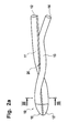
- FIGS. 2 a and 2 b schematically show a hollow-fiber membrane 10 reinforced as in FIG. 3, which is wound around a reinforcing wire 20.
- the arcuate region 15 is connected to the reinforcing wire 20, while the inflow 12 and outflow 14, for example, protrude from the reinforcing wire 20 along the length of the impermeable regions 12 'and 14'.
- FIG. 3 shows a cross section along the line III-III in FIG. 2a. It can be seen that the coating 20 'of the reinforcing wire 20 is melted and fused with the outer region of the hollow-fiber membrane.
- a catheter prepared as described under 4. is perfused with distilled water at a flow rate of 0.1 ⁇ l / min and introduced into a beaker containing 200 mg / dl glucose. At the exit of the catheter, a glucose content in the dialysis fluid of 199 mg / dl is measured.
- dead time (95) denotes the dead time until a signal change of 95% is reached.
- a catheter made as described in 4. is combined with a suitable flow index cell and perfused with distilled water at a flow rate of 0.1 ⁇ l / min.
- the catheter is alternately placed in beakers containing 200 mg / dl glucose and distilled water.
- the glucose concentration in the measuring cell follows the concentration in the beaker with a time delay. After subtraction of the delay caused by the volume of the measuring cell and its lead, the dead time (95) of the catheter remains 252 seconds.
Landscapes
- Health & Medical Sciences (AREA)
- Life Sciences & Earth Sciences (AREA)
- Animal Behavior & Ethology (AREA)
- General Health & Medical Sciences (AREA)
- Biophysics (AREA)
- Veterinary Medicine (AREA)
- Engineering & Computer Science (AREA)
- Biomedical Technology (AREA)
- Heart & Thoracic Surgery (AREA)
- Physics & Mathematics (AREA)
- Public Health (AREA)
- Pulmonology (AREA)
- Optics & Photonics (AREA)
- Medical Informatics (AREA)
- Surgery (AREA)
- Pathology (AREA)
- Hematology (AREA)
- Anesthesiology (AREA)
- Molecular Biology (AREA)
- External Artificial Organs (AREA)
- Separation Using Semi-Permeable Membranes (AREA)
- Artificial Filaments (AREA)
- Materials For Medical Uses (AREA)
- Media Introduction/Drainage Providing Device (AREA)
Applications Claiming Priority (3)
| Application Number | Priority Date | Filing Date | Title |
|---|---|---|---|
| SE0102879A SE519630C2 (sv) | 2001-08-30 | 2001-08-30 | Kateter och metod för tillverkning därav |
| SE0102879 | 2001-08-30 | ||
| PCT/EP2002/009686 WO2003020352A2 (de) | 2001-08-30 | 2002-08-30 | Katheter und verfahren zu seiner herstellung |
Publications (2)
| Publication Number | Publication Date |
|---|---|
| EP1423160A2 EP1423160A2 (de) | 2004-06-02 |
| EP1423160B1 true EP1423160B1 (de) | 2008-02-06 |
Family
ID=20285170
Family Applications (1)
| Application Number | Title | Priority Date | Filing Date |
|---|---|---|---|
| EP02797654A Expired - Lifetime EP1423160B1 (de) | 2001-08-30 | 2002-08-30 | Katheter und verfahren zu seiner herstellung |
Country Status (9)
| Country | Link |
|---|---|
| US (1) | US20050015044A1 (enExample) |
| EP (1) | EP1423160B1 (enExample) |
| JP (1) | JP4060793B2 (enExample) |
| AT (1) | ATE385428T1 (enExample) |
| CA (1) | CA2452510C (enExample) |
| DE (1) | DE50211650D1 (enExample) |
| ES (1) | ES2299629T3 (enExample) |
| SE (1) | SE519630C2 (enExample) |
| WO (1) | WO2003020352A2 (enExample) |
Families Citing this family (12)
| Publication number | Priority date | Publication date | Assignee | Title |
|---|---|---|---|---|
| CN104720887B (zh) | 2006-06-13 | 2017-05-10 | 直观外科手术操作公司 | 微创手术系统 |
| CN101578129B (zh) * | 2006-10-18 | 2012-03-28 | 甘布罗伦迪亚股份有限公司 | 中空纤维膜及其制备方法 |
| EP2077762B8 (en) * | 2006-10-18 | 2014-09-17 | Maquet Critical Care AB | Microdialysis catheter and a method of making a microdialysis catheter |
| KR101589746B1 (ko) * | 2009-04-13 | 2016-01-28 | 코오롱인더스트리 주식회사 | 복합 중공사막 및 그 제조방법 |
| GB0913645D0 (en) * | 2009-08-05 | 2009-09-16 | Nano Porous Solutions Ltd | A method of forming a fluid separation filter for use in a fluid separation device |
| CH701634A2 (de) * | 2009-08-07 | 2011-02-15 | Peter Schlumpf | Schutzhülle für einen Katheter. |
| CN102974231B (zh) * | 2012-11-16 | 2014-09-03 | 杭州天创环境科技股份有限公司 | 一种经强化织造管前处理的增强型聚合物复合膜制备方法 |
| US10575754B2 (en) | 2015-09-23 | 2020-03-03 | Covidien Lp | Catheter having a sensor and an extended working channel |
| CN107224624B (zh) * | 2017-06-12 | 2023-12-15 | 谢华南 | 血液透析器、血液透析装置及血液透析方法 |
| US10773051B2 (en) | 2018-01-24 | 2020-09-15 | Covidien Lp | Methods of manufacturing a catheter having a sensor |
| US10773053B2 (en) | 2018-01-24 | 2020-09-15 | Covidien Lp | Methods of manufacturing a catheter having a sensor |
| DK181117B1 (en) * | 2021-05-12 | 2023-01-10 | Flowsion As | Micro-dialysis probe with reinforcing tube |
Family Cites Families (21)
| Publication number | Priority date | Publication date | Assignee | Title |
|---|---|---|---|---|
| SE434214B (sv) | 1982-12-01 | 1984-07-16 | Carl Urban Ungerstedt | Dialysprob, avsedd for inforing i biologiska vevnader |
| US4765339A (en) * | 1986-06-04 | 1988-08-23 | Solutech, Inc. | Closed loop dialysis system |
| DE3878899T2 (de) * | 1987-07-30 | 1993-07-22 | Toray Industries | Poroese polytetrafluoraethylen-membran, trennvorrichtung unter verwendung dieser membran sowie verfahren zur herstellung. |
| US5405320A (en) * | 1990-01-08 | 1995-04-11 | The Curators Of The University Of Missouri | Multiple lumen catheter for hemodialysis |
| US5191900A (en) * | 1991-04-10 | 1993-03-09 | The Board Of Trustees Of The University Of Illinois | Dialysis probe |
| US5171227A (en) * | 1991-04-16 | 1992-12-15 | The Curators Of The University Of Missouri | Separable peritoneal dialysis catheter |
| US5879499A (en) * | 1996-06-17 | 1999-03-09 | Heartport, Inc. | Method of manufacture of a multi-lumen catheter |
| US6029671A (en) * | 1991-07-16 | 2000-02-29 | Heartport, Inc. | System and methods for performing endovascular procedures |
| US5141499A (en) * | 1991-10-09 | 1992-08-25 | Zappacosta Anthony R | Peritoneal dialysis catheter |
| US5228992A (en) * | 1992-03-03 | 1993-07-20 | Pall Corporation | Process for preparing hollow fiber separatory devices |
| US5350358A (en) * | 1992-12-22 | 1994-09-27 | Med-Pro Design, Inc. | Bent co-axial catheter |
| GB9424703D0 (en) * | 1994-12-07 | 1995-02-01 | Fsm Technologies Ltd | Plug |
| US5702601A (en) * | 1996-03-29 | 1997-12-30 | Praxiar Technology, Inc. | Structure enhancing hollow fiber module |
| JP3803421B2 (ja) * | 1996-04-26 | 2006-08-02 | 富士システムズ株式会社 | 気体交換装置 |
| DE19714572C1 (de) | 1997-04-09 | 1998-06-25 | Haindl Hans | Katheter zur Messung chemischer Parameter, insbesondere zum Einführen in biologisches Gewebe, Flüssigkeiten oder dergleichen |
| US6030358A (en) * | 1997-08-08 | 2000-02-29 | Odland; Rick Matthew | Microcatheter and method for site specific therapy |
| US5891114A (en) * | 1997-09-30 | 1999-04-06 | Target Therapeutics, Inc. | Soft-tip high performance braided catheter |
| NL1008315C2 (nl) | 1998-02-16 | 1999-08-25 | Stichting Fund Ond Material | Met Si-chip geïntegreerde microdialyse-sonde. |
| US6149665A (en) * | 1998-05-15 | 2000-11-21 | Shelhigh, Inc. | Intra vascular implant and method of manufacture thereof |
| DE19937099C2 (de) * | 1999-08-06 | 2001-07-12 | Disetronic Licensing Ag | Mikrodialysesonde |
| CA2407859C (en) * | 2001-03-06 | 2006-04-11 | Asahi Kasei Kabushiki Kaisha | Method for producing hollow fiber membrane |
-
2001
- 2001-08-30 SE SE0102879A patent/SE519630C2/sv not_active IP Right Cessation
-
2002
- 2002-08-30 DE DE50211650T patent/DE50211650D1/de not_active Expired - Lifetime
- 2002-08-30 US US10/488,135 patent/US20050015044A1/en not_active Abandoned
- 2002-08-30 EP EP02797654A patent/EP1423160B1/de not_active Expired - Lifetime
- 2002-08-30 WO PCT/EP2002/009686 patent/WO2003020352A2/de not_active Ceased
- 2002-08-30 ES ES02797654T patent/ES2299629T3/es not_active Expired - Lifetime
- 2002-08-30 AT AT02797654T patent/ATE385428T1/de not_active IP Right Cessation
- 2002-08-30 CA CA002452510A patent/CA2452510C/en not_active Expired - Fee Related
- 2002-08-30 JP JP2003524656A patent/JP4060793B2/ja not_active Expired - Fee Related
Also Published As
| Publication number | Publication date |
|---|---|
| SE0102879D0 (sv) | 2001-08-30 |
| DE50211650D1 (enExample) | 2008-03-20 |
| SE0102879L (sv) | 2003-03-01 |
| EP1423160A2 (de) | 2004-06-02 |
| ES2299629T3 (es) | 2008-06-01 |
| JP4060793B2 (ja) | 2008-03-12 |
| WO2003020352A3 (de) | 2003-11-27 |
| CA2452510C (en) | 2007-05-15 |
| US20050015044A1 (en) | 2005-01-20 |
| JP2005501612A (ja) | 2005-01-20 |
| ATE385428T1 (de) | 2008-02-15 |
| WO2003020352A2 (de) | 2003-03-13 |
| CA2452510A1 (en) | 2003-03-13 |
| SE519630C2 (sv) | 2003-03-18 |
Similar Documents
| Publication | Publication Date | Title |
|---|---|---|
| EP1423160B1 (de) | Katheter und verfahren zu seiner herstellung | |
| DE69731204T2 (de) | Verstärkter katheterkörper und zugehörige herstellungsmethode | |
| DE60007693T2 (de) | Katheter und Verfahren zu seiner Herstellung | |
| DE69828181T2 (de) | Ballonkatheter | |
| DE60316634T2 (de) | Führungsdraht | |
| DE69217134T2 (de) | Katheterführungsdraht und Katheter | |
| DE60028818T2 (de) | Gerät zum Verabreichen einer therapeutischen Substanz mit kontrollierter Dosierung bei endoluminalen Behandlungen | |
| DE69208463T2 (de) | Hohlfasern und Vorrichtung zu ihrer Herstellung | |
| DE60020675T2 (de) | Verfahren zur herstellung von hohlfiber-membranen | |
| DE19747057A1 (de) | Verfahren zur Herstellung einer röhrenförmigen Membranvorrichtung und dadurch hergestellte röhrenförmige Membranvorrichtungen | |
| EP1689517B1 (de) | Verfahren zum herstellen von rohrförmigen membranen | |
| DE20180138U1 (de) | Filterelement für Embolieschutzgerät | |
| DE19721703A1 (de) | Kathetersystem mit hoher Knickfestigkeit | |
| EP2184081A1 (de) | Katheterschaft | |
| DE10050099A1 (de) | Konduit-Herzklappenprothese und Verfahren zu ihrer Herstellung | |
| DE2542438A1 (de) | Dialysator, insbesondere fuer die haemodialyse und verfahren zu seiner herstellung | |
| EP1333779A1 (de) | Verfahren zur herstellung von dünnen membranartigen bauteilen | |
| EP3380216B1 (de) | Rohrförmiges filtermembran-element und verfahren zu seiner herstellung | |
| DE102005007596A1 (de) | Überzug, Herstellungsverfahren und Verfahren zum Aufbringen eines Überzuges auf ein medizinisches Instrument sowie medizinisches Instrument | |
| EP2085134B1 (de) | Hohlfaser-Separationsmembranen und Verfahren zu ihrer Herstellung | |
| EP3199343B1 (de) | Verbindungselement, verbindungsanordnung, verfahren zum herstellen eines verbindungselements und verfahren zum herstellen einer verbindungsanordnung | |
| DE68905840T2 (de) | Verfahren zum Verbinden von Kunststoff-Teilen unter Verwendung eines Vernetzungsmittels und einer elektrischen Widerstandsheizung. | |
| DE4131407C2 (de) | Modulkonstruktion mit anorganischen Membranen | |
| DE2537389A1 (de) | Verfahren zum herstellen einer filtrationsmembran aus kunststoff, filtrationsmembran, filtrationsmatte, hergestellt unter verwendung einer filtrationsmembran und filtrationssystem zur filtration waessriger loesungen und dispersionen | |
| EP3354331B1 (de) | Dialysator mit verbesserter interner filtration und verfahren zu dessen herstellung |
Legal Events
| Date | Code | Title | Description |
|---|---|---|---|
| PUAI | Public reference made under article 153(3) epc to a published international application that has entered the european phase |
Free format text: ORIGINAL CODE: 0009012 |
|
| AK | Designated contracting states |
Kind code of ref document: A2 Designated state(s): AT BE BG CH CY CZ DE DK EE ES FI FR GB GR IE IT LI LU MC NL PT SE SK TR |
|
| AX | Request for extension of the european patent |
Extension state: AL LT LV MK RO SI |
|
| 17P | Request for examination filed |
Effective date: 20040527 |
|
| GRAP | Despatch of communication of intention to grant a patent |
Free format text: ORIGINAL CODE: EPIDOSNIGR1 |
|
| GRAS | Grant fee paid |
Free format text: ORIGINAL CODE: EPIDOSNIGR3 |
|
| GRAA | (expected) grant |
Free format text: ORIGINAL CODE: 0009210 |
|
| AK | Designated contracting states |
Kind code of ref document: B1 Designated state(s): AT BE BG CH CY CZ DE DK EE ES FI FR GB GR IE IT LI LU MC NL PT SE SK TR |
|
| REG | Reference to a national code |
Ref country code: GB Ref legal event code: FG4D Free format text: NOT ENGLISH |
|
| REG | Reference to a national code |
Ref country code: CH Ref legal event code: EP |
|
| REG | Reference to a national code |
Ref country code: IE Ref legal event code: FG4D Free format text: LANGUAGE OF EP DOCUMENT: GERMAN |
|
| REF | Corresponds to: |
Ref document number: 50211650 Country of ref document: DE Date of ref document: 20080320 Kind code of ref document: P |
|
| GBT | Gb: translation of ep patent filed (gb section 77(6)(a)/1977) |
Effective date: 20080408 |
|
| REG | Reference to a national code |
Ref country code: ES Ref legal event code: FG2A Ref document number: 2299629 Country of ref document: ES Kind code of ref document: T3 |
|
| PG25 | Lapsed in a contracting state [announced via postgrant information from national office to epo] |
Ref country code: FI Free format text: LAPSE BECAUSE OF FAILURE TO SUBMIT A TRANSLATION OF THE DESCRIPTION OR TO PAY THE FEE WITHIN THE PRESCRIBED TIME-LIMIT Effective date: 20080206 |
|
| NLV1 | Nl: lapsed or annulled due to failure to fulfill the requirements of art. 29p and 29m of the patents act | ||
| ET | Fr: translation filed | ||
| REG | Reference to a national code |
Ref country code: IE Ref legal event code: FD4D |
|
| PG25 | Lapsed in a contracting state [announced via postgrant information from national office to epo] |
Ref country code: SE Free format text: LAPSE BECAUSE OF FAILURE TO SUBMIT A TRANSLATION OF THE DESCRIPTION OR TO PAY THE FEE WITHIN THE PRESCRIBED TIME-LIMIT Effective date: 20080506 Ref country code: CZ Free format text: LAPSE BECAUSE OF FAILURE TO SUBMIT A TRANSLATION OF THE DESCRIPTION OR TO PAY THE FEE WITHIN THE PRESCRIBED TIME-LIMIT Effective date: 20080206 Ref country code: NL Free format text: LAPSE BECAUSE OF FAILURE TO SUBMIT A TRANSLATION OF THE DESCRIPTION OR TO PAY THE FEE WITHIN THE PRESCRIBED TIME-LIMIT Effective date: 20080206 Ref country code: DK Free format text: LAPSE BECAUSE OF FAILURE TO SUBMIT A TRANSLATION OF THE DESCRIPTION OR TO PAY THE FEE WITHIN THE PRESCRIBED TIME-LIMIT Effective date: 20080206 Ref country code: PT Free format text: LAPSE BECAUSE OF FAILURE TO SUBMIT A TRANSLATION OF THE DESCRIPTION OR TO PAY THE FEE WITHIN THE PRESCRIBED TIME-LIMIT Effective date: 20080707 Ref country code: IE Free format text: LAPSE BECAUSE OF FAILURE TO SUBMIT A TRANSLATION OF THE DESCRIPTION OR TO PAY THE FEE WITHIN THE PRESCRIBED TIME-LIMIT Effective date: 20080206 Ref country code: SK Free format text: LAPSE BECAUSE OF FAILURE TO SUBMIT A TRANSLATION OF THE DESCRIPTION OR TO PAY THE FEE WITHIN THE PRESCRIBED TIME-LIMIT Effective date: 20080206 |
|
| PLBE | No opposition filed within time limit |
Free format text: ORIGINAL CODE: 0009261 |
|
| STAA | Information on the status of an ep patent application or granted ep patent |
Free format text: STATUS: NO OPPOSITION FILED WITHIN TIME LIMIT |
|
| 26N | No opposition filed |
Effective date: 20081107 |
|
| PG25 | Lapsed in a contracting state [announced via postgrant information from national office to epo] |
Ref country code: MC Free format text: LAPSE BECAUSE OF NON-PAYMENT OF DUE FEES Effective date: 20080831 |
|
| REG | Reference to a national code |
Ref country code: CH Ref legal event code: PL |
|
| PG25 | Lapsed in a contracting state [announced via postgrant information from national office to epo] |
Ref country code: BG Free format text: LAPSE BECAUSE OF FAILURE TO SUBMIT A TRANSLATION OF THE DESCRIPTION OR TO PAY THE FEE WITHIN THE PRESCRIBED TIME-LIMIT Effective date: 20080506 Ref country code: EE Free format text: LAPSE BECAUSE OF FAILURE TO SUBMIT A TRANSLATION OF THE DESCRIPTION OR TO PAY THE FEE WITHIN THE PRESCRIBED TIME-LIMIT Effective date: 20080206 |
|
| PG25 | Lapsed in a contracting state [announced via postgrant information from national office to epo] |
Ref country code: LI Free format text: LAPSE BECAUSE OF NON-PAYMENT OF DUE FEES Effective date: 20080831 Ref country code: CH Free format text: LAPSE BECAUSE OF NON-PAYMENT OF DUE FEES Effective date: 20080831 |
|
| PG25 | Lapsed in a contracting state [announced via postgrant information from national office to epo] |
Ref country code: BE Free format text: LAPSE BECAUSE OF NON-PAYMENT OF DUE FEES Effective date: 20080831 Ref country code: CY Free format text: LAPSE BECAUSE OF FAILURE TO SUBMIT A TRANSLATION OF THE DESCRIPTION OR TO PAY THE FEE WITHIN THE PRESCRIBED TIME-LIMIT Effective date: 20080206 |
|
| PG25 | Lapsed in a contracting state [announced via postgrant information from national office to epo] |
Ref country code: AT Free format text: LAPSE BECAUSE OF NON-PAYMENT OF DUE FEES Effective date: 20080830 |
|
| PGFP | Annual fee paid to national office [announced via postgrant information from national office to epo] |
Ref country code: ES Payment date: 20090804 Year of fee payment: 8 Ref country code: FR Payment date: 20090806 Year of fee payment: 8 |
|
| PGFP | Annual fee paid to national office [announced via postgrant information from national office to epo] |
Ref country code: DE Payment date: 20090831 Year of fee payment: 8 Ref country code: GB Payment date: 20090708 Year of fee payment: 8 |
|
| PGFP | Annual fee paid to national office [announced via postgrant information from national office to epo] |
Ref country code: IT Payment date: 20090813 Year of fee payment: 8 |
|
| PG25 | Lapsed in a contracting state [announced via postgrant information from national office to epo] |
Ref country code: LU Free format text: LAPSE BECAUSE OF NON-PAYMENT OF DUE FEES Effective date: 20080830 |
|
| PG25 | Lapsed in a contracting state [announced via postgrant information from national office to epo] |
Ref country code: TR Free format text: LAPSE BECAUSE OF FAILURE TO SUBMIT A TRANSLATION OF THE DESCRIPTION OR TO PAY THE FEE WITHIN THE PRESCRIBED TIME-LIMIT Effective date: 20080206 |
|
| PG25 | Lapsed in a contracting state [announced via postgrant information from national office to epo] |
Ref country code: GR Free format text: LAPSE BECAUSE OF FAILURE TO SUBMIT A TRANSLATION OF THE DESCRIPTION OR TO PAY THE FEE WITHIN THE PRESCRIBED TIME-LIMIT Effective date: 20080507 |
|
| GBPC | Gb: european patent ceased through non-payment of renewal fee |
Effective date: 20100830 |
|
| REG | Reference to a national code |
Ref country code: FR Ref legal event code: ST Effective date: 20110502 |
|
| PG25 | Lapsed in a contracting state [announced via postgrant information from national office to epo] |
Ref country code: IT Free format text: LAPSE BECAUSE OF NON-PAYMENT OF DUE FEES Effective date: 20100830 |
|
| REG | Reference to a national code |
Ref country code: DE Ref legal event code: R119 Ref document number: 50211650 Country of ref document: DE Effective date: 20110301 |
|
| PG25 | Lapsed in a contracting state [announced via postgrant information from national office to epo] |
Ref country code: DE Free format text: LAPSE BECAUSE OF NON-PAYMENT OF DUE FEES Effective date: 20110301 Ref country code: FR Free format text: LAPSE BECAUSE OF NON-PAYMENT OF DUE FEES Effective date: 20100831 |
|
| PG25 | Lapsed in a contracting state [announced via postgrant information from national office to epo] |
Ref country code: GB Free format text: LAPSE BECAUSE OF NON-PAYMENT OF DUE FEES Effective date: 20100830 |
|
| REG | Reference to a national code |
Ref country code: ES Ref legal event code: FD2A Effective date: 20111019 |
|
| PG25 | Lapsed in a contracting state [announced via postgrant information from national office to epo] |
Ref country code: ES Free format text: LAPSE BECAUSE OF NON-PAYMENT OF DUE FEES Effective date: 20100831 |