EP1423160B1 - Catheter and method for producing the same - Google Patents
Catheter and method for producing the same Download PDFInfo
- Publication number
- EP1423160B1 EP1423160B1 EP02797654A EP02797654A EP1423160B1 EP 1423160 B1 EP1423160 B1 EP 1423160B1 EP 02797654 A EP02797654 A EP 02797654A EP 02797654 A EP02797654 A EP 02797654A EP 1423160 B1 EP1423160 B1 EP 1423160B1
- Authority
- EP
- European Patent Office
- Prior art keywords
- fiber membrane
- hollow fiber
- catheter
- reinforcement
- hollow
- Prior art date
- Legal status (The legal status is an assumption and is not a legal conclusion. Google has not performed a legal analysis and makes no representation as to the accuracy of the status listed.)
- Expired - Lifetime
Links
- 238000004519 manufacturing process Methods 0.000 title claims abstract description 8
- 239000012528 membrane Substances 0.000 claims abstract description 110
- 239000012510 hollow fiber Substances 0.000 claims abstract description 89
- 239000002904 solvent Substances 0.000 claims abstract description 16
- 230000002787 reinforcement Effects 0.000 claims description 26
- 239000000853 adhesive Substances 0.000 claims description 17
- 230000001070 adhesive effect Effects 0.000 claims description 17
- 238000000034 method Methods 0.000 claims description 17
- 230000005855 radiation Effects 0.000 claims description 13
- 239000000463 material Substances 0.000 claims description 10
- 239000000385 dialysis solution Substances 0.000 claims description 8
- 230000009471 action Effects 0.000 claims description 7
- 238000000502 dialysis Methods 0.000 claims description 6
- 229920000642 polymer Polymers 0.000 claims description 6
- 239000011148 porous material Substances 0.000 claims description 6
- 238000002844 melting Methods 0.000 claims description 5
- 230000008018 melting Effects 0.000 claims description 5
- 239000000203 mixture Substances 0.000 claims description 4
- 229920005594 polymer fiber Polymers 0.000 claims description 4
- 239000000975 dye Substances 0.000 claims description 3
- 230000005670 electromagnetic radiation Effects 0.000 claims description 3
- 229910052751 metal Inorganic materials 0.000 claims description 3
- 239000002184 metal Substances 0.000 claims description 3
- 239000000049 pigment Substances 0.000 claims description 3
- 239000004033 plastic Substances 0.000 claims description 3
- 229920003023 plastic Polymers 0.000 claims description 3
- 239000000126 substance Substances 0.000 claims description 3
- 239000004831 Hot glue Substances 0.000 claims description 2
- 229920000914 Metallic fiber Polymers 0.000 claims description 2
- 239000004823 Reactive adhesive Substances 0.000 claims description 2
- 229910001092 metal group alloy Inorganic materials 0.000 claims description 2
- 229920013730 reactive polymer Polymers 0.000 claims description 2
- 238000000926 separation method Methods 0.000 claims description 2
- 239000000835 fiber Substances 0.000 claims 3
- 229910000831 Steel Inorganic materials 0.000 claims 1
- 238000004026 adhesive bonding Methods 0.000 claims 1
- 229910000510 noble metal Inorganic materials 0.000 claims 1
- 239000010959 steel Substances 0.000 claims 1
- 238000003466 welding Methods 0.000 claims 1
- 239000007943 implant Substances 0.000 abstract description 2
- 230000003014 reinforcing effect Effects 0.000 description 10
- WQZGKKKJIJFFOK-GASJEMHNSA-N Glucose Natural products OC[C@H]1OC(O)[C@H](O)[C@@H](O)[C@@H]1O WQZGKKKJIJFFOK-GASJEMHNSA-N 0.000 description 5
- 238000005452 bending Methods 0.000 description 5
- 239000008103 glucose Substances 0.000 description 5
- SECXISVLQFMRJM-UHFFFAOYSA-N N-Methylpyrrolidone Chemical compound CN1CCCC1=O SECXISVLQFMRJM-UHFFFAOYSA-N 0.000 description 4
- WYURNTSHIVDZCO-UHFFFAOYSA-N Tetrahydrofuran Chemical compound C1CCOC1 WYURNTSHIVDZCO-UHFFFAOYSA-N 0.000 description 4
- 230000008859 change Effects 0.000 description 4
- 238000001690 micro-dialysis Methods 0.000 description 4
- 229920002647 polyamide Polymers 0.000 description 4
- XLYOFNOQVPJJNP-UHFFFAOYSA-N water Substances O XLYOFNOQVPJJNP-UHFFFAOYSA-N 0.000 description 4
- ZMXDDKWLCZADIW-UHFFFAOYSA-N N,N-Dimethylformamide Chemical compound CN(C)C=O ZMXDDKWLCZADIW-UHFFFAOYSA-N 0.000 description 3
- 239000004952 Polyamide Substances 0.000 description 3
- 239000011248 coating agent Substances 0.000 description 3
- 238000000576 coating method Methods 0.000 description 3
- 239000012153 distilled water Substances 0.000 description 3
- 230000033001 locomotion Effects 0.000 description 3
- 238000012546 transfer Methods 0.000 description 3
- 229910001006 Constantan Inorganic materials 0.000 description 2
- IAZDPXIOMUYVGZ-UHFFFAOYSA-N Dimethylsulphoxide Chemical compound CS(C)=O IAZDPXIOMUYVGZ-UHFFFAOYSA-N 0.000 description 2
- KFZMGEQAYNKOFK-UHFFFAOYSA-N Isopropanol Chemical compound CC(C)O KFZMGEQAYNKOFK-UHFFFAOYSA-N 0.000 description 2
- 238000010521 absorption reaction Methods 0.000 description 2
- 238000004458 analytical method Methods 0.000 description 2
- 229920001577 copolymer Polymers 0.000 description 2
- 238000005259 measurement Methods 0.000 description 2
- 238000002360 preparation method Methods 0.000 description 2
- 238000007493 shaping process Methods 0.000 description 2
- 239000000243 solution Substances 0.000 description 2
- 239000011877 solvent mixture Substances 0.000 description 2
- 125000006850 spacer group Chemical group 0.000 description 2
- 239000010935 stainless steel Substances 0.000 description 2
- 229910001220 stainless steel Inorganic materials 0.000 description 2
- YLQBMQCUIZJEEH-UHFFFAOYSA-N tetrahydrofuran Natural products C=1C=COC=1 YLQBMQCUIZJEEH-UHFFFAOYSA-N 0.000 description 2
- VGGSQFUCUMXWEO-UHFFFAOYSA-N Ethene Chemical compound C=C VGGSQFUCUMXWEO-UHFFFAOYSA-N 0.000 description 1
- 239000005977 Ethylene Substances 0.000 description 1
- FXHOOIRPVKKKFG-UHFFFAOYSA-N N,N-Dimethylacetamide Chemical compound CN(C)C(C)=O FXHOOIRPVKKKFG-UHFFFAOYSA-N 0.000 description 1
- WHNWPMSKXPGLAX-UHFFFAOYSA-N N-Vinyl-2-pyrrolidone Chemical compound C=CN1CCCC1=O WHNWPMSKXPGLAX-UHFFFAOYSA-N 0.000 description 1
- 229920002367 Polyisobutene Polymers 0.000 description 1
- 239000004721 Polyphenylene oxide Substances 0.000 description 1
- 229920003079 Povidone K 17 Polymers 0.000 description 1
- XUIMIQQOPSSXEZ-UHFFFAOYSA-N Silicon Chemical compound [Si] XUIMIQQOPSSXEZ-UHFFFAOYSA-N 0.000 description 1
- 239000004830 Super Glue Substances 0.000 description 1
- XSTXAVWGXDQKEL-UHFFFAOYSA-N Trichloroethylene Chemical compound ClC=C(Cl)Cl XSTXAVWGXDQKEL-UHFFFAOYSA-N 0.000 description 1
- 238000003848 UV Light-Curing Methods 0.000 description 1
- 230000004913 activation Effects 0.000 description 1
- 238000013459 approach Methods 0.000 description 1
- 230000008901 benefit Effects 0.000 description 1
- WQZGKKKJIJFFOK-VFUOTHLCSA-N beta-D-glucose Chemical compound OC[C@H]1O[C@@H](O)[C@H](O)[C@@H](O)[C@@H]1O WQZGKKKJIJFFOK-VFUOTHLCSA-N 0.000 description 1
- 229920001400 block copolymer Polymers 0.000 description 1
- 210000001124 body fluid Anatomy 0.000 description 1
- 239000010839 body fluid Substances 0.000 description 1
- 150000004648 butanoic acid derivatives Chemical class 0.000 description 1
- 150000008280 chlorinated hydrocarbons Chemical class 0.000 description 1
- 230000006835 compression Effects 0.000 description 1
- 238000007906 compression Methods 0.000 description 1
- 238000013461 design Methods 0.000 description 1
- 238000011161 development Methods 0.000 description 1
- 230000018109 developmental process Effects 0.000 description 1
- 238000001035 drying Methods 0.000 description 1
- 238000005516 engineering process Methods 0.000 description 1
- 230000007613 environmental effect Effects 0.000 description 1
- 239000003822 epoxy resin Substances 0.000 description 1
- 238000001704 evaporation Methods 0.000 description 1
- 230000008020 evaporation Effects 0.000 description 1
- 230000005669 field effect Effects 0.000 description 1
- 238000011049 filling Methods 0.000 description 1
- 239000012530 fluid Substances 0.000 description 1
- 238000010438 heat treatment Methods 0.000 description 1
- 238000011835 investigation Methods 0.000 description 1
- 239000000155 melt Substances 0.000 description 1
- 238000012544 monitoring process Methods 0.000 description 1
- 229920000110 poly(aryl ether sulfone) Polymers 0.000 description 1
- 229920002492 poly(sulfone) Polymers 0.000 description 1
- 229920000647 polyepoxide Polymers 0.000 description 1
- 229920000728 polyester Polymers 0.000 description 1
- 229920000570 polyether Polymers 0.000 description 1
- 229920002959 polymer blend Polymers 0.000 description 1
- 229920000193 polymethacrylate Polymers 0.000 description 1
- 239000004814 polyurethane Substances 0.000 description 1
- 229920002635 polyurethane Polymers 0.000 description 1
- 229920000036 polyvinylpyrrolidone Polymers 0.000 description 1
- 239000010970 precious metal Substances 0.000 description 1
- 230000009467 reduction Effects 0.000 description 1
- 239000013558 reference substance Substances 0.000 description 1
- 230000001105 regulatory effect Effects 0.000 description 1
- 239000004576 sand Substances 0.000 description 1
- 229910052710 silicon Inorganic materials 0.000 description 1
- 239000010703 silicon Substances 0.000 description 1
- 239000007787 solid Substances 0.000 description 1
- 238000007669 thermal treatment Methods 0.000 description 1
- 229960002415 trichloroethylene Drugs 0.000 description 1
- 229920002554 vinyl polymer Polymers 0.000 description 1
- 238000004804 winding Methods 0.000 description 1
Images


Classifications
-
- A—HUMAN NECESSITIES
- A61—MEDICAL OR VETERINARY SCIENCE; HYGIENE
- A61M—DEVICES FOR INTRODUCING MEDIA INTO, OR ONTO, THE BODY; DEVICES FOR TRANSDUCING BODY MEDIA OR FOR TAKING MEDIA FROM THE BODY; DEVICES FOR PRODUCING OR ENDING SLEEP OR STUPOR
- A61M25/00—Catheters; Hollow probes
- A61M25/0043—Catheters; Hollow probes characterised by structural features
-
- A—HUMAN NECESSITIES
- A61—MEDICAL OR VETERINARY SCIENCE; HYGIENE
- A61B—DIAGNOSIS; SURGERY; IDENTIFICATION
- A61B5/00—Measuring for diagnostic purposes; Identification of persons
- A61B5/145—Measuring characteristics of blood in vivo, e.g. gas concentration, pH value; Measuring characteristics of body fluids or tissues, e.g. interstitial fluid, cerebral tissue
- A61B5/14525—Measuring characteristics of blood in vivo, e.g. gas concentration, pH value; Measuring characteristics of body fluids or tissues, e.g. interstitial fluid, cerebral tissue using microdialysis
- A61B5/14528—Measuring characteristics of blood in vivo, e.g. gas concentration, pH value; Measuring characteristics of body fluids or tissues, e.g. interstitial fluid, cerebral tissue using microdialysis invasively
-
- A—HUMAN NECESSITIES
- A61—MEDICAL OR VETERINARY SCIENCE; HYGIENE
- A61M—DEVICES FOR INTRODUCING MEDIA INTO, OR ONTO, THE BODY; DEVICES FOR TRANSDUCING BODY MEDIA OR FOR TAKING MEDIA FROM THE BODY; DEVICES FOR PRODUCING OR ENDING SLEEP OR STUPOR
- A61M25/00—Catheters; Hollow probes
- A61M25/0043—Catheters; Hollow probes characterised by structural features
- A61M2025/0059—Catheters; Hollow probes characterised by structural features having means for preventing the catheter, sheath or lumens from collapsing due to outer forces, e.g. compressing forces, or caused by twisting or kinking
-
- A—HUMAN NECESSITIES
- A61—MEDICAL OR VETERINARY SCIENCE; HYGIENE
- A61M—DEVICES FOR INTRODUCING MEDIA INTO, OR ONTO, THE BODY; DEVICES FOR TRANSDUCING BODY MEDIA OR FOR TAKING MEDIA FROM THE BODY; DEVICES FOR PRODUCING OR ENDING SLEEP OR STUPOR
- A61M25/00—Catheters; Hollow probes
- A61M25/0009—Making of catheters or other medical or surgical tubes
Abstract
Description
Die vorliegende Erfindung betrifft einen Katheter nach dem Oberbegriff des Anspruchs 1 sowie ein Verfahren zur Herstellung eines derartigen Katheters nach dem Oberbegriff des Anspruchs 16.The present invention relates to a catheter according to the preamble of claim 1 and to a method for producing such a catheter according to the preamble of claim 16.
Ein gattungsgemäßer Katheter für die Mikrodialyse ist aus der
Ein weiterer Katheter wird in der
Ein anderer Katheter zur Mikrodialyse ist in der
Bei allen bekannten Kathetern, bei denen konzentrische Rohre ineinander geschoben sind, ist es problematisch, dass die fluidische Kontaktierung, speziell des Spaltzwischenraumes zwischen dem äußeren und dem inneren Rohr bzw. der Hohlfasermembran und dem inneren Rohr, aufwendig ist und relativ viel Totvolumen erfordert. Totvolumina führen zu verlängerten Zeitspannen (Totzeit) zwischen einer Konzentrationsänderung und der Verfügbarkeit einer entsprechenden Probe in einer Messeinrichtung und sind daher zu minimieren. Da sich im Innern der Hohlfasermembran meistens die für die Trennung entscheidenden feinporigen Schichten befinden, besteht außerdem immer die Gefahr, dass beim Einschieben von Teilen in die Hohlfasermembran diese Trennschicht beschädigt wird.In all known catheters, in which concentric tubes are pushed into each other, it is problematic that the fluidic contact, especially the gap gap between the outer and the inner tube or the hollow fiber membrane and the inner tube, is complex and requires a relatively large dead volume. Dead volumes lead to prolonged periods (dead time) between a change in concentration and the availability of a corresponding sample in a measuring device and are therefore to be minimized. Since inside the hollow fiber membrane are usually the decisive for the separation of fine-pored layers, there is always the danger that when inserting parts into the hollow fiber membrane, this separating layer is damaged.
Die Aufgabe der vorliegenden Erfindung besteht somit darin, einen Katheter der oben genannten Art bereit zu stellen, welcher unkompliziert herzustellen ist und einfach implantiert und explantiert werden kann.The object of the present invention is therefore to provide a catheter of the above type, which is easy to manufacture and can be easily implanted and explanted.
Die Lösung besteht in einem Katheter mit den Merkmalen des Anspruchs 1 sowie in einem Verfahren mit den Merkmalen des Anspruchs 16.The solution consists in a catheter having the features of claim 1 and in a method having the features of claim 16.
Der erfindungsgemäße Katheter weist also eine um etwa 180°, d.h. etwa U-förmig gebogene Hohlfasermembran auf, wobei die beiden Schenkel des U möglichst eng beieinander liegen. Normalerweise würde dies dazu führen, dass die Hohlfasermembran abknickt, wodurch der Flüssigkeitsdurchtritt durch das Lumen unterbrochen würde. Überraschenderweise hat sich heraus gestellt, dass durch anisotropen Einsatz von Wärme oder Lösemitteln zumindest in diesem Bereich die Struktur der Hohlfasermembran so verändert wird, dass die Hohlfasermembran um etwa 180° gebogen werden kann, ohne abzuknicken, d.h. ohne dass sich das Lumen dabei verschließt.The catheter according to the invention thus has an approximately 180 °, i. approximately U-shaped curved hollow fiber membrane, wherein the two legs of the U are as close as possible to each other. Normally, this would cause the hollow fiber membrane to buckle, disrupting the passage of fluid through the lumen. Surprisingly, it has been found that by anisotropic use of heat or solvents at least in this area, the structure of the hollow fiber membrane is changed so that the hollow fiber membrane can be bent by about 180 ° without kinking, i. without the lumen closing.
Nachfolgende Untersuchungen haben ergeben, dass dies auf die anisotrope Einwirkung von Wärme oder Lösungsmitteln zurückführen ist. Durch die Einwirkung von Wärme oder Lösungsmittel wird das Membranmaterial weich. Die Oberflächen- bzw. Grenzflächenspannung des Membranmaterials bewirkt ein Schrumpfen der Poren. Dies äussert sich makroskopisch in einer Dimensionsänderung, d.h. die Membran wird kürzer, dünner und dichter. Da die Wärme oder die Lösemittel anisotrop, d.h von einer Seite her einwirken, kommt es zur Krümmung der Hohlfasermembran. Die Rückstellkräfte des von Wärme- oder Lösemitteleinwirkung nicht betroffenen Teils der Membran im Beigebereich werden durch von aussen wirkende mechanische Kräfte überwunden, um eine Biegung um 180 Grad zu erreichen. Beim Biegen um 180 Grad wird das Lumen zwar verengt, bleibt aber durchgängig.Subsequent investigations have shown that this is due to the anisotropic action of heat or solvents. The action of heat or solvent softens the membrane material. The surface or interfacial tension of the membrane material causes the pores to shrink. This manifests itself macroscopically in a dimensional change, ie the membrane becomes shorter, thinner and denser. Because the heat or the Solvent anisotropic, ie act from one side, it comes to the curvature of the hollow fiber membrane. The restoring forces of the part of the membrane in the area which is not affected by heat or solvent are overcome by external mechanical forces in order to achieve a bend of 180 degrees. When bending by 180 degrees, the lumen is indeed narrowed, but remains consistent.
Weiterhin ist es vorteilhaft, dass die Anschlüsse des erfindungsgemäßen Katheters faktisch zwei Schläuche sind, die einfach konnektiert werden können. Die Dialyseflüssigkeit tritt an einem Ende der Hohlfasermembran in diese ein und am anderen Ende wieder aus.Furthermore, it is advantageous that the connections of the catheter according to the invention are in fact two tubes that can be easily connected. The dialysis fluid enters this at one end of the hollow fiber membrane and out again at the other end.
Der erfindungsgemäße Katheter für die Mikrodialyse weist einen sehr geringen Gesamtdurchmesser auf. Der erfindungsgemäße Katheter ist daher nicht nur sehr einfach zu implantieren und zu explantieren, er bietet auch gegenüber dem Stand der Technik einen deutlich verbesserten Tragekomfort und deutlich reduzierte Totzeiten.The catheter according to the invention for microdialysis has a very small overall diameter. The catheter according to the invention is therefore not only very easy to implant and explant, it also offers over the prior art significantly improved comfort and significantly reduced dead times.
Das erfindungsgemäße Verfahren zeichnet sich dadurch aus, dass die Hohlfasermembran zumindest im zu biegenden Bereich wärmebehandelt oder mit mindestens einem Lösemittel behandelt wird. Durch die anisotrope Einbringung von Wärme oder die anisotrope Behandlung mit mindestens einem Lösemittel wird die Struktur der Hohlfasermembran so verändert, dass sie bei einem minimalen Gesamtdurchmesser des Katheters etwa U-förmig gebogen werden kann, ohne abzuknicken und das Lumen zu verschließen. Dabei ist es besonders vorteilhaft, dass die Hohlfasermembran nur von außen bearbeitet werden muss, um einen erfindungsgemäßen Katheter für die Mikrodialyse herzustellen. Es zeigte sich auch, dass es nicht notwendig ist, das Lumen zu stützen, wie es z. Bsp- beim Biegen von metallischen Rohren durch Einfüllen von Sand Stand der Technik ist. Ferner ist es nicht mehr nötig, einen Schlauch oder ein anderes Teil in das Innere einer Hohlfasermembran einzuschieben oder einen Membranschlauch in ein Gehäuse einzubringen. Es besteht auch nicht mehr die Gefahr, die innere Trennschicht der Hohlfasermembran zu beschädigen.The method according to the invention is characterized in that the hollow-fiber membrane is heat-treated at least in the region to be bent or treated with at least one solvent. By the anisotropic introduction of heat or the anisotropic treatment with at least one solvent, the structure of the hollow fiber membrane is changed so that it can be bent approximately U-shaped with a minimum total diameter of the catheter, without kinking and closing the lumen. It is particularly advantageous that the hollow fiber membrane must be processed only from the outside to produce a catheter according to the invention for microdialysis. It was also shown that it is not necessary to support the lumen, as it is z. For example Bending of metallic pipes by filling sand is state of the art. Furthermore, it is no longer necessary to insert a tube or another part into the interior of a hollow-fiber membrane or to introduce a membrane tube into a housing. There is also no longer any danger of damaging the inner separating layer of the hollow-fiber membrane.
Vorteilhafte Weiterbildungen ergeben sich aus den Unteransprüchen. Der Abstand (a) zwischen den beiden Schenkeln der Hohlfasermembran sollte vorzugsweise kleiner als 50 % des Durchmessers (d) der Hohlfasermembran sein. Alternativ oder gleichzeitig sollte der Gesamtdurchmesser des Katheters vorteilhafterweise kleiner als der 2,5fache Durchmesser der Hohlfasermembran sein. Dies bewirkt eine möglichst geringe Baugröße und einen besonders kleinen Gesamtdurchmesser des fertigen Katheters. Die Hohlfasermembran ist weiterhin im U-förmigen Bereich vorzugsweise um 180° +/- 5° gebogen und kann zur Verbesserung der Zugfestigkeit eine Verstärkung aufweisen. Durch die Verwendung einer Verstärkung wird ferner die Explantation weiter vereinfacht, da das Risiko, die Membran oder Membranteile zu verlieren, weiter verringert wird. Die Verstärkung kann bspw. ein Draht, ein Faden und/oder eine Litze sein, die bspw. parallel zu den beiden Schenkeln geführt sein kann und mit diesen verbunden, bspw. verklebt oder verschweißt ist. Die Verstärkung kann aus einem Metall, einer Metalllegierung oder einem Kunststoff bestehen. Gut geeignet sind Drähte aus Edelstahl, einem Edelmetall oder aus monofilen Polymerfasern, Fäden aus Polymerfasern oder Litzen aus mehreren dünnen metallischen Fäden.Advantageous developments emerge from the subclaims. The distance (a) between the two limbs of the hollow-fiber membrane should preferably be less than 50% of the diameter (d) of the hollow-fiber membrane. Alternatively or simultaneously, the total diameter of the catheter should advantageously be less than 2.5 times the diameter of the hollow fiber membrane. This causes the smallest possible size and a particularly small overall diameter of the finished catheter. The hollow fiber membrane is further preferably bent in the U-shaped region by 180 ° +/- 5 ° and may have a gain to improve the tensile strength. In addition, the use of reinforcement further simplifies explantation by further reducing the risk of losing the membrane or membrane parts. The reinforcement may, for example, be a wire, a thread and / or a stranded wire, which may, for example, be guided parallel to the two legs and connected to them, for example glued or welded. The reinforcement may consist of a metal, a metal alloy or a plastic. Well suited wires are stainless steel, a precious metal or monofilament polymer fibers, threads of polymer fibers or strands of several thin metallic threads.
Der erfindungsgemäße Katheter kann im Bereich des Zuflusses und/oder des Abflusses der Dialyseflüssigkeit eine flüssigkeitsimpermeable Zone aufweisen, die auch als "Schaft" für die Konnektierung der Enden dienen kann.In the region of the inflow and / or outflow of the dialysis fluid, the catheter according to the invention can have a liquid-impermeable zone, which can also serve as a "shaft" for the connection of the ends.
Die Hohlfasermembran kann ferner zumindest punktuell mindestens eine strahlungsabsorbierende Substanz, wie Farbstoffe und/oder Pigmente aufweisen, um bei der Einbringung von Wärme durch elektromagnetische Strahlung die Absorption der Strahlung und damit den Wärmeeintrag zu steigern.The hollow-fiber membrane may further comprise, at least at certain points, at least one radiation-absorbing substance, such as dyes and / or pigments, in order to increase the absorption of the radiation and thus the heat input when heat is introduced by electromagnetic radiation.
Bei der Herstellung des erfindungsgemässen Katheters erfolgt die Einwirkung von Lösemitteln bevorzugt durch Aufbringen eines kleinen Tropfens eines geeigneten Lösemittels oder Lösemittelgemisches. Die Grösse des Tropfens richtet sich nach dem Durchmesser und der Wanddicke der Hohlfasermembran. Das Volumen sollte ausreichen, um die Porenstruktur der Membran auf einer Länge entsprechend dem ein- bis eineinhalbfachen Durchmesser und ca. 50 % des Membranumfangs aufzufüllen. Geeignete Lösemittel sind solche, die das Polymer der Membran lösen oder erweichen und zum Schrumpfen bringen, z.B. Dimethylformamid, Dimethylsulfoxid, Dimethylacetamid oder Tetrahydrofuran. Chlorierte Kohlenwasserstoffe z.B. Trichlorethen sind aus Umweltgründen nicht bevorzugt. Besonders bevorzugt sind Lösemittel oder Lösemittelgemische, die durch Verdampfen leicht wieder entfernt werden können, z.B. Gemische aus Isopropanol und Tetrahydrofuran.In the preparation of the catheter according to the invention, the action of solvents is preferably carried out by applying a small drop of a suitable solvent or solvent mixture. The size of the drop depends on the diameter and the wall thickness of the hollow-fiber membrane. The volume should be sufficient to fill the pore structure of the membrane to a length corresponding to one to one and a half times the diameter and about 50% of the membrane circumference. Suitable solvents are those which dissolve or soften the polymer of the membrane and cause it to shrink, e.g. Dimethylformamide, dimethylsulfoxide, dimethylacetamide or tetrahydrofuran. Chlorinated hydrocarbons e.g. Trichloroethene is not preferred for environmental reasons. Particularly preferred are solvents or solvent mixtures which can be easily removed by evaporation, e.g. Mixtures of isopropanol and tetrahydrofuran.
Bei der Herstellung des erfindungsgemäßen Katheters hat sich die Einbringung von Wärme über den direkten Kontakt mit einem elektrisch aufgeheizten Draht als besonders geeignet erwiesen. Die Einbringung von Wärme durch elektromagnetische Strahlung ist auch möglich, bspw. durch Laserstrahlung, Mikrowellenstrahlung oder Hochfrequenzstrahlung, unter der Voraussetzung, dass die Strahlung von der Hohlfasermembran zumindest im gebogenen Bereich absorbiert wird.In the manufacture of the catheter according to the invention, the introduction of heat via direct contact with an electrically heated wire has proved to be particularly suitable. The introduction of heat by electromagnetic radiation is also possible, for example by laser radiation, microwave radiation or high-frequency radiation, provided that the radiation is absorbed by the hollow-fiber membrane at least in the bent region.
Als Hohlfasermembran sind handelsübliche Dialysehohlfasern, bspw. aus Polyamiden, Polyamid S, Polyarylethersulfonen, Polymethacrylat, Polysulfonen oder Polycarbonat-Polyether-Blockcopolymeren (bspw. unter dem Handelsnamen Gambrane erhältlich) geeignet. Besonders geeignet sind Hohlfasermembranen mit einer asymmetrischen Struktur, dergestalt, dass das Lumen von einer feinporigen Trennschicht umgeben ist, während die Wandung nach außen zunehmend größere und/oder offene Poren aufweist.Commercially available dialysis hollow fibers, for example from polyamides, polyamide S, polyaryl ether sulfones, polymethacrylate, polysulfones or polycarbonate-polyether block copolymers (available, for example, under the trade name Gambrane) are suitable as the hollow-fiber membrane. Particularly suitable are hollow fiber membranes with an asymmetric structure, such that the lumen is surrounded by a fine-pored separating layer, while the wall has increasingly larger and / or open pores to the outside.
Der Außendurchmesser der Hohlfasermembran sollte 600 µm nicht überschreiten, besser noch unter 300 µm und besonders bevorzugt unter 200 µm liegen. Geeignet sind auch Hohlfasermembranen mit kleinem Durchmesser, bspw. einem Innendurchmesser im Bereich von 50 bis 100 µm, vorzugsweise 60 bis 90 µm und geringer Wandstärke, bspw. 20 bis 80 µm, vorzugsweise 40 µm. Letztere können zu erfindungsgemäßen Kathetern mit besonders geringem Gesamtdurchmesser verarbeitet werden.The outer diameter of the hollow-fiber membrane should not exceed 600 microns, better still below 300 microns and more preferably below 200 microns. Also suitable are hollow-fiber membranes with a small diameter, for example an inner diameter in the range from 50 to 100 μm, preferably 60 to 90 μm and small wall thickness, for example 20 to 80 μm, preferably 40 μm. The latter can be processed into catheters according to the invention having a particularly small overall diameter.
Die Verklebung mit der Verstärkung kann durch Aufgabe einer dünnen Kleberschicht auf die Verstärkung und anschließende Verbindung mit der Hohlfasermembran erfolgen. Als Kleber eignen sich Reaktivkleber wie Cyanacrylatkleber oder Polyurethankleber sowie lösemittelhaltige Kleber oder durch Strahlung aktivierbare Kleber oder thermisch aktivierbare Polymere oder Kleber (Schmelzkleber) wie Ethylen/Ethylacrylat-Copolymere, Ethylen/Vinylacrylat-Copolymere, Polyamide, Polyester, Polyisobutylen oder Polyvinylbutyrate sowie die Membranmaterialien selbst. Es ist auch möglich, die Verstärkung direkt mit der Membran zu verbinden ("Bonden"), indem die Hohlfasermembran in innigen Kontakt mit der Verstärkung gebracht und die Verstärkung auf eine Temperatur oberhalb der Schmelztemperatur des Membranmaterials und/oder, bei Verwendung eines Verstärkers aus Kunststoff, des Verstärkermaterials gebracht wird. Dieses Verfahren eignet sich auch zur Aktivierung eines thermisch aktivierbaren Klebers. Wenn ein metallischer Verstärker verwendet wird, kann die Erwärmung durch Zuführung elektrischer Energie über den Verstärker erfolgen. Dieses Verfahren ist besonders bevorzugt, da überraschenderweise gefunden wurde, dass beim Aufschmelzen nur die äußere großporige und/oder offenporige Kontaktzone zwischen Membran und Verstärkung verdichtet wird, der zugehörige Bereich der Trennschicht jedoch nicht verändert wird und durchgängig bleibt. Damit wird die Austauschleistung durch diese Art der Verklebung zwischen der Hohlfasermembran und der Verstärkung nur minimal reduziert.The bonding with the reinforcement can be done by applying a thin layer of adhesive to the reinforcement and subsequent connection to the hollow fiber membrane. Suitable adhesives include reactive adhesives, such as cyanoacrylate adhesives or polyurethane adhesives, as well as solvent-based adhesives or radiation-activatable adhesives or thermally activatable polymers or adhesives (hot-melt adhesives), such as ethylene / ethyl acrylate copolymers, ethylene / vinyl acrylate copolymers, polyamides, polyesters, polyisobutylene or polyvinyl butyrates and the membrane materials themselves It is also possible to bond the reinforcement directly to the membrane ("bonding") by bringing the hollow fiber membrane into intimate contact with the reinforcement and raising the reinforcement to a temperature above the melting temperature of the membrane material and / or when using an amplifier Plastic, the amplifier material is brought. This method is suitable also for activation of a thermally activated adhesive. When a metallic amplifier is used, the heating can be done by supplying electrical energy through the amplifier. This method is particularly preferred since it has surprisingly been found that only the outer large-pored and / or open-pore contact zone between membrane and reinforcement is compacted during melting, but the associated region of the separating layer is not changed and remains continuous. Thus, the exchange performance is minimally reduced by this type of bonding between the hollow fiber membrane and the reinforcement.
Zur Sicherung der Verstärkung des erfindungsgemäßen Katheters kann zusätzlich ein Tropfen eines reaktiven Polymergemisches am vorderen, d.h. am gebogenen Ende des Katheters aufgebracht werden, welcher sowohl die Haftung zwischen Membran und Verstärkung weiter verbessert als auch eventuell vorhandene Schwachstellen und Lecks in der Membran im gebogenen Bereich verschließt. Dazu können auch die bereits genannten Klebstoffe verwendet werden.To secure the reinforcement of the catheter according to the invention, a drop of a reactive polymer mixture at the front, i. be applied to the curved end of the catheter, which further improves both the adhesion between the membrane and reinforcement and closes any existing weak points and leaks in the membrane in the bent region. For this purpose, the already mentioned adhesives can be used.
Die flüssigkeitsimpermeable Zone im Bereich des Zuflusses und/oder Abflusses des erfindungsgemäßen Katheters kann bspw. durch Tränken der Hohlfasermembran mit einem geeigneten Polymer oder einem Polymergemisch, bspw. einem Kleber, geschaffen werden, welches dann thermisch oder reaktiv ausgehärtet werden kann. Bevorzugt ist aber, diese Bereiche bis in die Nähe des Schmelzpunktes des Membranmaterials zu erhitzen, so dass die Poren in der Hohlfasermembran kollabieren und die Membranwandung auf diese Weise praktisch flüssigkeitsundurchlässig wird. Damit geht eine Schrumpfung der Hohlfasermembran einher, was neben der Reduzierung der Wandstärke auch eine Reduzierung des Innendurchmessers zur Folge hat. Der Vorteil dieser Vorgehensweise besteht darin, dass durch die Reduzierung des Innendurchmessers der Hohlfasermembran das Totvolumen des erfindungsgemäßen Katheters reduziert wird. Dadurch wiederum wird die Verweilzeit einer Probe im Bereich des Zuflusses und/oder Abflusses reduziert und eine Messgröße, bspw. eine Änderung des Glucosegehalts im Gewebe, kann schneller detektiert werden.The liquid-impermeable zone in the region of the inflow and / or outflow of the catheter according to the invention can be provided, for example, by impregnating the hollow-fiber membrane with a suitable polymer or a polymer mixture, for example an adhesive, which can then be cured thermally or reactively. However, it is preferred to heat these areas to near the melting point of the membrane material, so that the pores in the hollow-fiber membrane collapse and the membrane wall becomes practically liquid-impermeable in this way. This is accompanied by a shrinkage of the hollow fiber membrane, which in addition to reducing the wall thickness also has a reduction in the inner diameter result. The advantage of this approach is that by reducing the inner diameter of the Hollow fiber membrane, the dead volume of the catheter according to the invention is reduced. This in turn reduces the residence time of a sample in the region of the inflow and / or outflow, and a measured variable, for example a change in the glucose content in the tissue, can be detected more quickly.
Die thermische Behandlung im Bereich des Zuflusses und/oder Abflusses kann durch Einwirkung von Heißluft, durch partielles Einbringen des Katheters in eine heiße Kammer oder zwischen zwei erhitzte Backen oder durch Einwirkung von Strahlung erfolgen. Bspw. IR-Strahlung eignet sich besonders gut zur präzisen räumlichen Formung des Katheters, wenn dafür gesorgt wird, dass nur in den aufzuheizenden Segmenten eine Absorption der Strahlung stattfindet. Dies kann durch Zugabe geeigneter strahlungsabsorbierender Substanzen wie Farbstoffe oder Pigmente erfolgen.The thermal treatment in the region of the inflow and / or outflow can be effected by the action of hot air, by partial introduction of the catheter into a hot chamber or between two heated jaws or by the action of radiation. For example. IR radiation is particularly well suited for precise spatial shaping of the catheter, if it is ensured that only in the segments to be heated, absorption of the radiation takes place. This can be done by adding suitable radiation absorbing substances such as dyes or pigments.
Die Ausführung des Zuflusses und/oder Abflusses des erfindungsgemäßen Katheters wird so gewählt, dass die beiden Enden der Hohlfasermembran getrennt voneinander vorliegen. Sie können dann in an sich bekannter Weise in Ausnehmungen in einem Schlauch oder in einer Trägerplatte mit miniaturisierten Fließwegen eingelegt und dann eingeklebt werden. Die Verstärkung kann dann in oder an einem Schlauch oder einer Trägerplatte mit miniaturisierten Fließwegen, bspw. in einer Ausnehmung oder an einer Fläche der Trägerplatte in an sich bekannter Weise befestigt, z. Bsp. eingeklebt werden.The design of the inflow and / or outflow of the catheter according to the invention is chosen so that the two ends of the hollow-fiber membrane are present separately. They can then be inserted in a conventional manner in recesses in a tube or in a carrier plate with miniaturized flow paths and then glued. The reinforcement can then be fixed in or on a hose or a support plate with miniaturized flow paths, for example. In a recess or on a surface of the support plate in a conventional manner, for. For example, be glued.
Im Folgenden wird ein Ausführungsbeispiel der vorliegenden Erfindung näher erläutert. Es zeigen:
- Figur 1
- eine schematische, nicht maßstabsgetreue Darstellung einer Hohlfasermembran für einen erfindungsgemäßen Katheter nach dem Biegen;
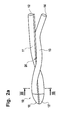
- Figur 2a
- den hinteren Teil einer Hohlfasermembran aus Figur 1 mit einer Verstärkung;
- Figur 2b
- die Hohlfasermembran aus Figur 1 mit einer Verstärkung in ihrer Gesamtheit;
- Figur 3
- einen schematischen Querschnitt durch die Hohlfasermembran aus den Figuren 2a und 2b.
- FIG. 1
- a schematic, not to scale representation of a hollow fiber membrane for a catheter according to the invention after bending;
- FIG. 2a
- the rear part of a hollow fiber membrane of Figure 1 with a reinforcement;
- FIG. 2b
- the hollow fiber membrane of Figure 1 with a reinforcement in its entirety;
- FIG. 3
- a schematic cross section through the hollow fiber membrane of Figures 2a and 2b.
Eine PAS-Hohlfasermembran der Fa. Gambro Dialysatoren, Hechingen, Deutschland, mit einem Innendurchmesser von 214 µm und einer Wandstärke von 43 µm wird auf eine Länge von 50 mm geschnitten. Das Hohlfasermembranstück wird mittig auf einen elektrisch beheizbaren Konstantandraht mit einem Durchmesser von 250 µm gelegt. Die beiden Enden der Hohlfasermembran werden mit einer Kraft von 1 mg belastet. Dieser Draht wird elektrisch beheizt. Aus einem stromgeregelten Netzteil fließt über einen Zeitraum von 2x2 Sekunden ein Strom von 1,7 A. Unter dem Einfluss des erhitzten Drahtes verformt sich die Hohlfasermembran an der Auflagestelle und biegt sich. Dabei bilden die beiden Schenkel einen Winkel von 15° bis 30°. Durch vorsichtiges Zusammendrücken im Augenblick des Abschalten des Stromes im zweiten Zyklus kann der Winkel auf praktisch Null reduziert werden.A PAS hollow-fiber membrane from Gambro Dialysatoren, Hechingen, Germany, with an inner diameter of 214 μm and a wall thickness of 43 μm, is cut to a length of 50 mm. The hollow fiber membrane piece is placed centrally on an electrically heatable constantan wire with a diameter of 250 μm. The two ends of the hollow fiber membrane are loaded with a force of 1 mg. This wire is electrically heated. From a current-regulated power supply flows over a period of 2x2 seconds, a current of 1.7 A. Under the influence of the heated wire, the hollow fiber membrane deforms at the support point and bends. The two legs form an angle of 15 ° to 30 °. By careful compression at the moment of turning off the current in the second cycle, the angle can be reduced to practically zero.
Figur 1 zeigt schematisch eine solche U-förmig gebogene Hohlfasermembran 10 mit zwei Schenkeln 11, 13, die zu je einem Zufluss 12 bzw. Abfluss 14 münden und einem gebogenen Bereich 15. Die Fließrichtung der Dialyseflüssigkeit ist mit Pfeilen angedeutet. Der Abstand a zwischen den Schenkeln 11, 13 beträgt weniger als 50 % des Durchmessers d der Hohlfasermembran 10. Im Bereich des Zuflusses 12 und des Abflusses 14 befindet sich je ein flüssigkeitsimpermeabler Bereich 12', 14'. Ein weiterer flüssigkeitsimpermeabler Bereich 15' befindet sich im gebogenen Bereich 15, welcher mit einem Klebstoff getränkt ist.FIG. 1 schematically shows such a U-shaped hollow-
Eine PAS-Hohlfasermembran der Fa. Gambro Dialysatoren, Hechingen, Deutschland, mit einem Innendurchmesser von 214 µm und einer Wandstärke von 43 µm wird auf eine Länge von 50 mm geschnitten und auf eine Auflage gelegt. Die Auflage hat in der Mitte eine schmale, gerade Ausnehmung, in der ein senkrecht zur Oberfläche orientierter, elektrisch beheizbarer Konstantandraht mit einem Durchmesser von 250 µm in einer gleichförmigen Bewegung mit ca. 10 mm/s geführt wird. Durch den Draht fließt ein Strom von .1,7 A. Bei der Vorwärtsbewegung trifft der Draht mittig auf die Hohlfasermembran und schleppt sie mit. Seitlich des Verfahrweges des Drahtes befinden sich Wandungen, deren Abstand vom Pfad des Drahtes sich asymptotisch auf 500 µm verringert. Unter Einfluss des durch den Stromfluss beheizten Drahtes und der Wandungen biegt sich die mitgeschleppte Hohlfaser in gewünschter Weise. Durch das Zusammenfahren zweier seitlicher Backen aus Silikon im Augenblick des Abschaltens des Stromes kann der Winkel zwischen den beiden Schenkeln auf praktisch Null reduziert werden. Die Bewegungen des Drahtes und der Backen und der Stromfluss werden automatisch gesteuert. Damit ist eine reproduzierbare Ausformung der Biegung problemlos möglich.A PAS hollow-fiber membrane from Gambro Dialysatoren, Hechingen, Germany, with an inner diameter of 214 μm and a wall thickness of 43 μm, is cut to a length of 50 mm and placed on a support. The support has a narrow, straight recess in the center, in which a perpendicular to the surface oriented, electrically heatable constantan wire with a diameter of 250 microns in a uniform motion with about 10 mm / s is performed. A current of .1.7 A flows through the wire. During forward movement, the wire hits the center of the hollow-fiber membrane and carries it along. Side of the path of the wire are walls whose distance from the path of the wire is asymptotically reduced to 500 μm. Under the influence of the heated by the flow of current wire and the walls, the entrained hollow fiber bends in the desired manner. By bringing together two silicon side jaws at the moment of turning off the current, the angle between the two legs can be reduced to virtually zero. The movements of the wire and the jaws and the flow of current are controlled automatically. For a reproducible shaping of the bend is easily possible.
Zur Verstärkung wird ein Draht aus rostfreiem Stahl (Werkstoff-Nr. 1.4301, Fe/Cr18/Ni10, Härtegrad: geglüht, Durchmesser: 0,05 mm) der Fa. Goodfellow Deutschland, Bad Nauheim, Deutschland, mit der Bestellnummer FE225110 eingesetzt. Zur Verbesserung der Haftung wird der Draht mit einer dünnen Schicht aus einem Polyamid überzogen. Dazu wird der Draht mit einer Geschwindigkeit von 3,1 m/min durch eine Beschichtdüse (Durchmesser 300 µm) gezogen und allseitig mit einer Schicht einer Lösung aus 15 Gew.-% Trogamid T3000, Hersteller Creanova, Marl, Deutschland, 7 Gew.-% PVP Plasdone C-15, Hersteller ISP Technologies, Inc., Wayne, USA und 78 Gew.-% NMP (N-methyl-2-pyrrolidon), Hersteller Merck, Darmstadt, Deutschland, versehen. Der so beschichtete Draht wird durch ein Wasserbad gezogen, um das Lösemittel auszuwaschen. Es bildet sich eine feste weiße Schicht mit einer Dicke von ca. 100 µm. Nach dem Trocknen an Luft ist der beschichtete Verstärkungsdraht einsetzbar.For reinforcement, a wire made of stainless steel (material No. 1.4301, Fe / Cr18 / Ni10, degree of hardness: annealed, diameter: 0.05 mm) from Goodfellow Germany, Bad Nauheim, Germany, used with the order number FE225110. To improve adhesion, the wire is coated with a thin layer of polyamide. For this purpose, the wire is drawn at a speed of 3.1 m / min through a coating nozzle (diameter 300 microns) and on all sides with a layer of a solution of 15 wt .-% Trogamid T3000, manufacturer Creanova, Marl, Germany, 7 wt. % PVP Plasdone C-15, manufacturer ISP Technologies, Inc., Wayne, USA, and 78 wt% NMP (N-methyl-2-pyrrolidone), manufacturer Merck, Darmstadt, Germany. The coated wire is pulled through a water bath to wash out the solvent. It forms a solid white layer with a thickness of about 100 microns. After drying in air, the coated reinforcing wire can be used.
Eine wie unter 1a. oder 1b. behandelte Hohlfasermembran wird so um einen wie unter 2 behandelten, praktisch endlosen Verstärkungsdraht gewickelt, dass die beiden Schenkel der Hohlfasermembran dicht aneinander liegen und gemeinsam eine Windung mit einer Steigung von 5 bis 10 mm pro Windung bilden. Die Biegung wird dabei direkt auf den Draht gedrückt, während Anfang und Ende der Hohlfasermembran auf der Länge von je ca. 3 mm vom Draht abstehen. Durch den Draht wird über eine Dauer von 3,5 Sekunden ein elektrischer Strom von 0,2 A geleitet. Der durch den Strom erhitzte Draht schmilzt die Beschichtung des Verstärkungsdrahtes und die Hohlfasermembran im Außenbereich auf. Nach Abschalten des Stroms kühlt der Draht ab, und die Hohlfasermembran haftet fest.One as under 1a. or 1b. treated hollow fiber membrane is wound around a treated as in 2, practically endless reinforcing wire that the two legs of the hollow fiber membrane are close to each other and together form a winding with a slope of 5 to 10 mm per turn. The bend is thereby pressed directly onto the wire, while the beginning and end of the hollow-fiber membrane project on the length of about 3 mm from the wire. An electrical current of 0.2 A is passed through the wire over a period of 3.5 seconds. The wire heated by the current melts the coating of the reinforcing wire and the hollow fiber membrane on the outside. After turning off the power, the wire cools and the hollow fiber membrane adheres firmly.
Die wie unter 1a. oder 1b. und 3. behandelte Hohlfasermembran wird vereinzelt. Dazu wird der Verstärkungsdraht unmittelbar vor der Biegung abgeschnitten und auf ca. 30 mm abgelängt. Die beiden offenen Enden der Hohlfasermembran werden in einen Schlauch mit einem Innendurchmesser von 500 µm eingeklebt. Als Klebstoff dient Epoxidharz UHU plus schnellfest, UHU Vertrieb GmbH, Bühl/Baden, Deutschland. Die beiden Enden der Hohlfasermembran werden auf einer Länge von ca. 4 mm mit Klebstoff getränkt und damit impermeabel gemacht. Als Klebstoff dient UV-härtendes Dymax 1181-M, Dymax Europe GmbH, Frankfurt a.M., Deutschland. Als permeable Austauschlänge verbleiben 2x20 mm.The as under 1a. or 1b. and 3. treated hollow fiber membrane is singulated. For this purpose, the reinforcing wire is cut immediately before the bend and cut to about 30 mm. The two open ends of the hollow fiber membrane are glued into a tube with an inside diameter of 500 μm. The adhesive used is epoxy resin UHU plus fast-fast, UHU Vertrieb GmbH, Buhl / Baden, Germany. The two ends of the hollow-fiber membrane are impregnated with adhesive over a length of approx. 4 mm, thus making them impermeable. The adhesive used is UV-curing Dymax 1181-M, Dymax Europe GmbH, Frankfurt a.M., Germany. The permeable replacement length is 2x20 mm.
Die Figuren 2a und 2b zeigen schematisch eine wie unter 3. verstärkte Hohlfasermembran 10, die um einen Verstärkungsdraht 20 gewickelt ist. Der gebogene Bereich 15 ist mit dem Verstärkungsdraht 20 verbunden, während Zufluss 12 und Abfluss 14 bspw. über die Länge der impermeablen Bereiche 12' und 14' vom Verstärkungsdraht 20 abstehen. Angedeutet sind ferner Schläuche 21, 22, in welche der Zufluss 12 und der Abfluss 14 eingeklebt sind.FIGS. 2 a and 2 b schematically show a hollow-
Figur 3 zeigt einen Querschnitt entlang der Linie III-III in Figur 2a. Man erkennt, dass die Beschichtung 20' des Verstärkungsdrahts 20 aufgeschmolzen und mit dem Außenbereich der Hohlfasermembran verschmolzen ist.FIG. 3 shows a cross section along the line III-III in FIG. 2a. It can be seen that the coating 20 'of the reinforcing
Ein wie unter 4. hergestellter Katheter wird mit destilliertem Wasser mit einem Fluss von 0,1 µl/min durchströmt und in ein Becherglas mit 200 mg/dl Glucose eingebracht. Am Ausgang des Katheters wird ein Glucosegehalt in der Dialyseflüssigkeit von 199 mg/dl gemessen.A catheter prepared as described under 4. is perfused with distilled water at a flow rate of 0.1 μl / min and introduced into a beaker containing 200 mg / dl glucose. At the exit of the catheter, a glucose content in the dialysis fluid of 199 mg / dl is measured.
Der Begriff Totzeit (95) bezeichnet die Totzeit bis zum Erreichen einer Signaländerung von 95%. Ein wie unter 4. hergestellter Katheter wird mit einer geeigneten Durchflussbrechungsindexmesszelle kombiniert und mit destilliertem Wasser mit einem Fluss von 0,1 µl/min durchströmt. Der Katheter wird wechselweise in Bechergläser mit 200 mg/dl Glucose und mit destilliertem Wasser eingebracht. Die Glucosekonzentration in der Messzelle folgt der Konzentration im Becherglas mit Zeitverzögerung. Nach Subtraktion der durch das Volumen der Messzelle und ihrer Zuleitung verursachten Verzögerung verbleiben für die Totzeit(95) des Katheters 252 Sekunden.The term dead time (95) denotes the dead time until a signal change of 95% is reached. A catheter made as described in 4. is combined with a suitable flow index cell and perfused with distilled water at a flow rate of 0.1 μl / min. The catheter is alternately placed in beakers containing 200 mg / dl glucose and distilled water. The glucose concentration in the measuring cell follows the concentration in the beaker with a time delay. After subtraction of the delay caused by the volume of the measuring cell and its lead, the dead time (95) of the catheter remains 252 seconds.
Claims (29)
- Catheter with a hollow fiber membrane (10) bent essentially in a U-shape comprising two legs (11, 13) and a bent section (15), characterized in that the distance (a) between the two legs (11, 13) is less than 50 % of the diameter (d) of the hollow fiber membrane (10).
- Catheter as claimed in claim 1, characterized in that the overall diameter of the catheter is less than 2.5 times the diameter of the hollow fiber membrane.
- Catheter as claimed in claim 1 or 2, characterized in that the U-shaped section of the hollow fiber membrane (10) is bent by 180° ± 5°.
- Catheter as claimed in one of the previous claims, characterized in that the hollow fiber membrane (10) has a reinforcement (20).
- Catheter as claimed in claim 4, characterized in that a wire, thread and/or braid are provided as the reinforcement (20) which is bonded to the two legs (11, 13) by for example gluing or welding.
- Catheter as claimed in claim 4 or 5, characterized in that the reinforcement (20) consists of a metal, a metal alloy or a plastic.
- Catheter as claimed in claim 5 or 6, characterized in that the wire consists of high-grade steel, a noble metal or monofil polymer fibers.
- Catheter as claimed in claim 5 or 6, characterized in that the thread consists of polymer fibers.
- Catheter as claimed in claim 5 or 6, characterized in that the braid consists of several thin metallic threads.
- Catheter as claimed in one of the claims 5 to 9, characterized in that at least a particular site on the hollow fiber membrane (10) has at least one substance that absorbs radiation preferably dyes and/or pigments.
- Catheter as claimed in one of the previous claims, characterized in that a liquid-impermeable zone (12', 14') is provided in the area of the inlet (12) and/or outlet (14) for the dialysis fluid.
- Catheter as claimed in one of the previous claims, characterized in that the hollow fiber membrane has an asymmetric structure such that the lumen is surrounded by a fine-pored separation layer whereas the wall has pores which increase in size towards the outside.
- Catheter as claimed in one of the previous claims, characterized in that the external diameter of the hollow fiber membrane (10) is less than 600 µm, preferably less than 300 µm and particularly preferably less than 200 µm.
- Catheter as claimed in one of the previous claims, characterized in that the internal diameter of the hollow fiber membrane (10) is 50 to 100 µm, preferably 60 to 90 µm.
- Catheter as claimed in one of the previous claims, characterized in that the wall thickness of the hollow fiber membrane (10) is 20 to 80 µm, preferably 40 µm.
- Method for producing a catheter with a hollow fiber membrane (10) which is essentially bent in a U-shape or for producing a hollow fiber membrane which is essentially bent in a U-shape, characterized in that the hollow fiber membrane (10) is heat-treated and/or treated with at least one solvent at least in the region to be bent.
- Method as claimed in claim 16, characterized in that the hollow fiber membrane is treated by direct contact with an electrically heated wire and/or by the action of electromagnetic radiation.
- Method as claimed in one of the claims 16 or 17, characterized in that commercial hollow dialysis fibers are used.
- Method as claimed in one of the claims 16 or 17, characterized in that hollow dialysis fibers having a smaller diameter and/or smaller wall thickness than commercial hollow dialysis fibers are used.
- Method as claimed in one of the claims 16 to 19, characterized in that in order to bond a reinforcement (20), firstly a thin layer of adhesive is applied to the reinforcement (20) which is then bonded to the hollow fiber membrane (10).
- Method as claimed in claim 20, characterized in that reactive adhesives, solvent-containing adhesives, polymers or adhesives that can be activated by radiation or thermally activatable adhesives (hot-melt adhesives) are used for the bonding.
- Method as claimed in one of the claims 16 to 19, characterized in that the reinforcement (20) is bonded directly to the hollow fiber membrane (10).
- Method as claimed in claim 22, characterized in that the hollow fiber membrane (10) is intimately contacted with the reinforcement (20) and the reinforcement is heated to a temperature above the melting temperature of the membrane material and/or above that of the reinforcement material.
- Method as claimed in one of the claims 16 to 23, characterized in that a drop of a reactive polymer mixture is applied to the front end of the hollow fiber membrane (10).
- Method as claimed in one of the claims 16 to 24, characterized in that the hollow fiber membrane (10) in the area of the inlet (12) and/or outlet (14) of the catheter is impregnated with a hardenable polymer and the polymer is subsequently hardened.
- Method as claimed in one of the claims 16 to 24, characterized in that the hollow fiber membrane (10) in the area of the inlet (12) and/or outlet (14) of the catheter is heated to near the melting point of the membrane material.
- Method as claimed in claim 26, characterized in that the hollow fiber membrane (10) is heated by the action of radiation, preferably IR radiation.
- Method as claimed in one of the claims 16 to 27, characterized in that the ends of the hollow fiber membrane (10) are inserted into a tube or a carrier plate with miniaturized flow paths and then glued in.
- Method as claimed in claim 28, characterized in that the reinforcement (20) is attached or glued in or on a tube or a carrier plate with miniaturized flow paths.
Applications Claiming Priority (3)
| Application Number | Priority Date | Filing Date | Title |
|---|---|---|---|
| SE0102879A SE519630C2 (en) | 2001-08-30 | 2001-08-30 | Catheter and method of manufacture thereof |
| SE0102879 | 2001-08-30 | ||
| PCT/EP2002/009686 WO2003020352A2 (en) | 2001-08-30 | 2002-08-30 | Catheter and method for producing the same |
Publications (2)
| Publication Number | Publication Date |
|---|---|
| EP1423160A2 EP1423160A2 (en) | 2004-06-02 |
| EP1423160B1 true EP1423160B1 (en) | 2008-02-06 |
Family
ID=20285170
Family Applications (1)
| Application Number | Title | Priority Date | Filing Date |
|---|---|---|---|
| EP02797654A Expired - Lifetime EP1423160B1 (en) | 2001-08-30 | 2002-08-30 | Catheter and method for producing the same |
Country Status (9)
| Country | Link |
|---|---|
| US (1) | US20050015044A1 (en) |
| EP (1) | EP1423160B1 (en) |
| JP (1) | JP4060793B2 (en) |
| AT (1) | ATE385428T1 (en) |
| CA (1) | CA2452510C (en) |
| DE (1) | DE50211650D1 (en) |
| ES (1) | ES2299629T3 (en) |
| SE (1) | SE519630C2 (en) |
| WO (1) | WO2003020352A2 (en) |
Families Citing this family (12)
| Publication number | Priority date | Publication date | Assignee | Title |
|---|---|---|---|---|
| CN104688281B (en) | 2006-06-13 | 2017-04-19 | 直观外科手术操作公司 | Minimally invasive surgical system |
| WO2008048183A1 (en) * | 2006-10-18 | 2008-04-24 | Cma/Microdialysis Ab | Microdialysis catheter and a method of making a microdialysis catheter |
| ATE487533T1 (en) * | 2006-10-18 | 2010-11-15 | Gambro Lundia Ab | HOLLOW FIBER MEMBRANE AND METHOD FOR PRODUCING SAME |
| KR101589746B1 (en) * | 2009-04-13 | 2016-01-28 | 코오롱인더스트리 주식회사 | Hollow fiber membrane and method for manufacturing the same |
| GB0913645D0 (en) * | 2009-08-05 | 2009-09-16 | Nano Porous Solutions Ltd | A method of forming a fluid separation filter for use in a fluid separation device |
| CH701634A2 (en) * | 2009-08-07 | 2011-02-15 | Peter Schlumpf | Sleeve for a catheter. |
| CN102974231B (en) * | 2012-11-16 | 2014-09-03 | 杭州天创环境科技股份有限公司 | Preparation method of enhanced polymer composite membrane preprocessed by reinforced weaving tube |
| US10575754B2 (en) | 2015-09-23 | 2020-03-03 | Covidien Lp | Catheter having a sensor and an extended working channel |
| CN107224624B (en) * | 2017-06-12 | 2023-12-15 | 谢华南 | Hemodialysis device, hemodialysis apparatus, and hemodialysis method |
| US10773051B2 (en) | 2018-01-24 | 2020-09-15 | Covidien Lp | Methods of manufacturing a catheter having a sensor |
| US10773053B2 (en) | 2018-01-24 | 2020-09-15 | Covidien Lp | Methods of manufacturing a catheter having a sensor |
| DK181117B1 (en) * | 2021-05-12 | 2023-01-10 | Flowsion As | Micro-dialysis probe with reinforcing tube |
Family Cites Families (21)
| Publication number | Priority date | Publication date | Assignee | Title |
|---|---|---|---|---|
| SE434214B (en) | 1982-12-01 | 1984-07-16 | Carl Urban Ungerstedt | DIALYSIS PROBLEM, INTENDED FOR INFORMATION IN BIOLOGICAL Tissues |
| US4765339A (en) * | 1986-06-04 | 1988-08-23 | Solutech, Inc. | Closed loop dialysis system |
| DE3878899T2 (en) * | 1987-07-30 | 1993-07-22 | Toray Industries | POROESE POLYTETRAFLUORAETHYLENE MEMBRANE, SEPARATING DEVICE USING THIS MEMBRANE AND METHOD FOR THE PRODUCTION THEREOF. |
| US5405320A (en) * | 1990-01-08 | 1995-04-11 | The Curators Of The University Of Missouri | Multiple lumen catheter for hemodialysis |
| US5191900A (en) * | 1991-04-10 | 1993-03-09 | The Board Of Trustees Of The University Of Illinois | Dialysis probe |
| US5171227A (en) * | 1991-04-16 | 1992-12-15 | The Curators Of The University Of Missouri | Separable peritoneal dialysis catheter |
| US6029671A (en) * | 1991-07-16 | 2000-02-29 | Heartport, Inc. | System and methods for performing endovascular procedures |
| US5879499A (en) * | 1996-06-17 | 1999-03-09 | Heartport, Inc. | Method of manufacture of a multi-lumen catheter |
| US5141499A (en) * | 1991-10-09 | 1992-08-25 | Zappacosta Anthony R | Peritoneal dialysis catheter |
| US5228992A (en) * | 1992-03-03 | 1993-07-20 | Pall Corporation | Process for preparing hollow fiber separatory devices |
| US5350358A (en) * | 1992-12-22 | 1994-09-27 | Med-Pro Design, Inc. | Bent co-axial catheter |
| GB9424703D0 (en) * | 1994-12-07 | 1995-02-01 | Fsm Technologies Ltd | Plug |
| US5702601A (en) * | 1996-03-29 | 1997-12-30 | Praxiar Technology, Inc. | Structure enhancing hollow fiber module |
| JP3803421B2 (en) * | 1996-04-26 | 2006-08-02 | 富士システムズ株式会社 | Gas exchange device |
| DE19714572C1 (en) | 1997-04-09 | 1998-06-25 | Haindl Hans | Catheter for measuring chemical parameters in biological tissue |
| US6030358A (en) * | 1997-08-08 | 2000-02-29 | Odland; Rick Matthew | Microcatheter and method for site specific therapy |
| US5891114A (en) * | 1997-09-30 | 1999-04-06 | Target Therapeutics, Inc. | Soft-tip high performance braided catheter |
| NL1008315C2 (en) | 1998-02-16 | 1999-08-25 | Stichting Fund Ond Material | Microdialysis probe integrated with Si chip. |
| DE69915821T2 (en) * | 1998-05-15 | 2005-03-17 | Shlomo Gabbay | INTRAVASCULAR IMPLANT AND METHOD OF MANUFACTURING THEREOF |
| DE19937099C2 (en) * | 1999-08-06 | 2001-07-12 | Disetronic Licensing Ag | Microdialysis probe |
| CN100448517C (en) * | 2001-03-06 | 2009-01-07 | 旭化成化学株式会社 | Method for producing hollow yarn film |
-
2001
- 2001-08-30 SE SE0102879A patent/SE519630C2/en not_active IP Right Cessation
-
2002
- 2002-08-30 AT AT02797654T patent/ATE385428T1/en not_active IP Right Cessation
- 2002-08-30 EP EP02797654A patent/EP1423160B1/en not_active Expired - Lifetime
- 2002-08-30 CA CA002452510A patent/CA2452510C/en not_active Expired - Fee Related
- 2002-08-30 WO PCT/EP2002/009686 patent/WO2003020352A2/en active IP Right Grant
- 2002-08-30 JP JP2003524656A patent/JP4060793B2/en not_active Expired - Fee Related
- 2002-08-30 DE DE50211650T patent/DE50211650D1/de not_active Expired - Lifetime
- 2002-08-30 ES ES02797654T patent/ES2299629T3/en not_active Expired - Lifetime
- 2002-08-30 US US10/488,135 patent/US20050015044A1/en not_active Abandoned
Also Published As
| Publication number | Publication date |
|---|---|
| JP4060793B2 (en) | 2008-03-12 |
| CA2452510C (en) | 2007-05-15 |
| ES2299629T3 (en) | 2008-06-01 |
| SE0102879D0 (en) | 2001-08-30 |
| JP2005501612A (en) | 2005-01-20 |
| SE0102879L (en) | 2003-03-01 |
| SE519630C2 (en) | 2003-03-18 |
| ATE385428T1 (en) | 2008-02-15 |
| US20050015044A1 (en) | 2005-01-20 |
| EP1423160A2 (en) | 2004-06-02 |
| WO2003020352A3 (en) | 2003-11-27 |
| CA2452510A1 (en) | 2003-03-13 |
| DE50211650D1 (en) | 2008-03-20 |
| WO2003020352A2 (en) | 2003-03-13 |
Similar Documents
| Publication | Publication Date | Title |
|---|---|---|
| EP1423160B1 (en) | Catheter and method for producing the same | |
| DE2824934C2 (en) | Method and device for producing a tube sheet | |
| DE69731204T2 (en) | REINFORCED CATHETER BODY AND ASSOCIATED MANUFACTURING METHOD | |
| DE60007693T2 (en) | Catheter and method for its manufacture | |
| DE69828181T2 (en) | BALLOON CATHETER | |
| DE60028818T2 (en) | Apparatus for administering a controlled-dose therapeutic substance in endoluminal treatments | |
| DE60020675T2 (en) | METHOD FOR PRODUCING HOLLOW FIBER MEMBRANES | |
| DE19747057A1 (en) | Method of manufacturing a tubular membrane device and tubular membrane devices made thereby | |
| EP1259207A1 (en) | Single-use absorbent sanitary article | |
| DE2647384C3 (en) | Artificial heart chamber | |
| EP1689517B1 (en) | Method for the production of tubular membranes | |
| DE10050099A1 (en) | Tubular cardiac valve prosthesis has individual parts all made of polyurethane, forming an integrated component | |
| DE2542438A1 (en) | DIALYZER, IN PARTICULAR FOR HAEMODIALYSIS AND METHOD OF ITS MANUFACTURING | |
| WO2006086968A1 (en) | Coating and method for applying a coating to a medical instrument, and medical instrument | |
| EP1333779A1 (en) | Method for producing thin membrane-type structural components | |
| DE102007032771A1 (en) | Sterile connecting system for thermoplastic hoses comprises clamp for hose ends, heater and cutter consisting of metal ribbon which passes from full spool to empty one | |
| DE69736758T2 (en) | Semipermeable capillaries and method and apparatus for their preparation | |
| WO2017088975A1 (en) | Tubular filter membrane element, and method for the production thereof | |
| EP1525013B1 (en) | Intravenous oxygenator | |
| DE2854444A1 (en) | ION-SENSITIVE CAPPILLARY ELECTRODE AND METHOD OF MANUFACTURING IT | |
| DE102011082470A1 (en) | Fitting structure of connection assembly of measuring device for examining e.g. high performance liquid chromatography (HPLC) liquid, has capillary whose end portion dimension is adjusted with respect to that of adjacent portion | |
| EP2085134B1 (en) | Hollow fibre separation membranes and method for their production | |
| DE4131407C2 (en) | Module construction with inorganic membranes | |
| DE3906027A1 (en) | HOSE FOR CONDUCTING MEDICAL LIQUIDS | |
| DE102012208709B3 (en) | Method and device for producing a thread connection and adhesive for producing such a thread connection |
Legal Events
| Date | Code | Title | Description |
|---|---|---|---|
| PUAI | Public reference made under article 153(3) epc to a published international application that has entered the european phase |
Free format text: ORIGINAL CODE: 0009012 |
|
| AK | Designated contracting states |
Kind code of ref document: A2 Designated state(s): AT BE BG CH CY CZ DE DK EE ES FI FR GB GR IE IT LI LU MC NL PT SE SK TR |
|
| AX | Request for extension of the european patent |
Extension state: AL LT LV MK RO SI |
|
| 17P | Request for examination filed |
Effective date: 20040527 |
|
| GRAP | Despatch of communication of intention to grant a patent |
Free format text: ORIGINAL CODE: EPIDOSNIGR1 |
|
| GRAS | Grant fee paid |
Free format text: ORIGINAL CODE: EPIDOSNIGR3 |
|
| GRAA | (expected) grant |
Free format text: ORIGINAL CODE: 0009210 |
|
| AK | Designated contracting states |
Kind code of ref document: B1 Designated state(s): AT BE BG CH CY CZ DE DK EE ES FI FR GB GR IE IT LI LU MC NL PT SE SK TR |
|
| REG | Reference to a national code |
Ref country code: GB Ref legal event code: FG4D Free format text: NOT ENGLISH |
|
| REG | Reference to a national code |
Ref country code: CH Ref legal event code: EP |
|
| REG | Reference to a national code |
Ref country code: IE Ref legal event code: FG4D Free format text: LANGUAGE OF EP DOCUMENT: GERMAN |
|
| REF | Corresponds to: |
Ref document number: 50211650 Country of ref document: DE Date of ref document: 20080320 Kind code of ref document: P |
|
| GBT | Gb: translation of ep patent filed (gb section 77(6)(a)/1977) |
Effective date: 20080408 |
|
| REG | Reference to a national code |
Ref country code: ES Ref legal event code: FG2A Ref document number: 2299629 Country of ref document: ES Kind code of ref document: T3 |
|
| PG25 | Lapsed in a contracting state [announced via postgrant information from national office to epo] |
Ref country code: FI Free format text: LAPSE BECAUSE OF FAILURE TO SUBMIT A TRANSLATION OF THE DESCRIPTION OR TO PAY THE FEE WITHIN THE PRESCRIBED TIME-LIMIT Effective date: 20080206 |
|
| NLV1 | Nl: lapsed or annulled due to failure to fulfill the requirements of art. 29p and 29m of the patents act | ||
| ET | Fr: translation filed | ||
| REG | Reference to a national code |
Ref country code: IE Ref legal event code: FD4D |
|
| PG25 | Lapsed in a contracting state [announced via postgrant information from national office to epo] |
Ref country code: SE Free format text: LAPSE BECAUSE OF FAILURE TO SUBMIT A TRANSLATION OF THE DESCRIPTION OR TO PAY THE FEE WITHIN THE PRESCRIBED TIME-LIMIT Effective date: 20080506 Ref country code: CZ Free format text: LAPSE BECAUSE OF FAILURE TO SUBMIT A TRANSLATION OF THE DESCRIPTION OR TO PAY THE FEE WITHIN THE PRESCRIBED TIME-LIMIT Effective date: 20080206 Ref country code: NL Free format text: LAPSE BECAUSE OF FAILURE TO SUBMIT A TRANSLATION OF THE DESCRIPTION OR TO PAY THE FEE WITHIN THE PRESCRIBED TIME-LIMIT Effective date: 20080206 Ref country code: DK Free format text: LAPSE BECAUSE OF FAILURE TO SUBMIT A TRANSLATION OF THE DESCRIPTION OR TO PAY THE FEE WITHIN THE PRESCRIBED TIME-LIMIT Effective date: 20080206 Ref country code: PT Free format text: LAPSE BECAUSE OF FAILURE TO SUBMIT A TRANSLATION OF THE DESCRIPTION OR TO PAY THE FEE WITHIN THE PRESCRIBED TIME-LIMIT Effective date: 20080707 Ref country code: IE Free format text: LAPSE BECAUSE OF FAILURE TO SUBMIT A TRANSLATION OF THE DESCRIPTION OR TO PAY THE FEE WITHIN THE PRESCRIBED TIME-LIMIT Effective date: 20080206 Ref country code: SK Free format text: LAPSE BECAUSE OF FAILURE TO SUBMIT A TRANSLATION OF THE DESCRIPTION OR TO PAY THE FEE WITHIN THE PRESCRIBED TIME-LIMIT Effective date: 20080206 |
|
| PLBE | No opposition filed within time limit |
Free format text: ORIGINAL CODE: 0009261 |
|
| STAA | Information on the status of an ep patent application or granted ep patent |
Free format text: STATUS: NO OPPOSITION FILED WITHIN TIME LIMIT |
|
| 26N | No opposition filed |
Effective date: 20081107 |
|
| PG25 | Lapsed in a contracting state [announced via postgrant information from national office to epo] |
Ref country code: MC Free format text: LAPSE BECAUSE OF NON-PAYMENT OF DUE FEES Effective date: 20080831 |
|
| REG | Reference to a national code |
Ref country code: CH Ref legal event code: PL |
|
| PG25 | Lapsed in a contracting state [announced via postgrant information from national office to epo] |
Ref country code: BG Free format text: LAPSE BECAUSE OF FAILURE TO SUBMIT A TRANSLATION OF THE DESCRIPTION OR TO PAY THE FEE WITHIN THE PRESCRIBED TIME-LIMIT Effective date: 20080506 Ref country code: EE Free format text: LAPSE BECAUSE OF FAILURE TO SUBMIT A TRANSLATION OF THE DESCRIPTION OR TO PAY THE FEE WITHIN THE PRESCRIBED TIME-LIMIT Effective date: 20080206 |
|
| PG25 | Lapsed in a contracting state [announced via postgrant information from national office to epo] |
Ref country code: LI Free format text: LAPSE BECAUSE OF NON-PAYMENT OF DUE FEES Effective date: 20080831 Ref country code: CH Free format text: LAPSE BECAUSE OF NON-PAYMENT OF DUE FEES Effective date: 20080831 |
|
| PG25 | Lapsed in a contracting state [announced via postgrant information from national office to epo] |
Ref country code: BE Free format text: LAPSE BECAUSE OF NON-PAYMENT OF DUE FEES Effective date: 20080831 Ref country code: CY Free format text: LAPSE BECAUSE OF FAILURE TO SUBMIT A TRANSLATION OF THE DESCRIPTION OR TO PAY THE FEE WITHIN THE PRESCRIBED TIME-LIMIT Effective date: 20080206 |
|
| PG25 | Lapsed in a contracting state [announced via postgrant information from national office to epo] |
Ref country code: AT Free format text: LAPSE BECAUSE OF NON-PAYMENT OF DUE FEES Effective date: 20080830 |
|
| PGFP | Annual fee paid to national office [announced via postgrant information from national office to epo] |
Ref country code: ES Payment date: 20090804 Year of fee payment: 8 Ref country code: FR Payment date: 20090806 Year of fee payment: 8 |
|
| PGFP | Annual fee paid to national office [announced via postgrant information from national office to epo] |
Ref country code: DE Payment date: 20090831 Year of fee payment: 8 Ref country code: GB Payment date: 20090708 Year of fee payment: 8 |
|
| PGFP | Annual fee paid to national office [announced via postgrant information from national office to epo] |
Ref country code: IT Payment date: 20090813 Year of fee payment: 8 |
|
| PG25 | Lapsed in a contracting state [announced via postgrant information from national office to epo] |
Ref country code: LU Free format text: LAPSE BECAUSE OF NON-PAYMENT OF DUE FEES Effective date: 20080830 |
|
| PG25 | Lapsed in a contracting state [announced via postgrant information from national office to epo] |
Ref country code: TR Free format text: LAPSE BECAUSE OF FAILURE TO SUBMIT A TRANSLATION OF THE DESCRIPTION OR TO PAY THE FEE WITHIN THE PRESCRIBED TIME-LIMIT Effective date: 20080206 |
|
| PG25 | Lapsed in a contracting state [announced via postgrant information from national office to epo] |
Ref country code: GR Free format text: LAPSE BECAUSE OF FAILURE TO SUBMIT A TRANSLATION OF THE DESCRIPTION OR TO PAY THE FEE WITHIN THE PRESCRIBED TIME-LIMIT Effective date: 20080507 |
|
| GBPC | Gb: european patent ceased through non-payment of renewal fee |
Effective date: 20100830 |
|
| REG | Reference to a national code |
Ref country code: FR Ref legal event code: ST Effective date: 20110502 |
|
| PG25 | Lapsed in a contracting state [announced via postgrant information from national office to epo] |
Ref country code: IT Free format text: LAPSE BECAUSE OF NON-PAYMENT OF DUE FEES Effective date: 20100830 |
|
| REG | Reference to a national code |
Ref country code: DE Ref legal event code: R119 Ref document number: 50211650 Country of ref document: DE Effective date: 20110301 |
|
| PG25 | Lapsed in a contracting state [announced via postgrant information from national office to epo] |
Ref country code: DE Free format text: LAPSE BECAUSE OF NON-PAYMENT OF DUE FEES Effective date: 20110301 Ref country code: FR Free format text: LAPSE BECAUSE OF NON-PAYMENT OF DUE FEES Effective date: 20100831 |
|
| PG25 | Lapsed in a contracting state [announced via postgrant information from national office to epo] |
Ref country code: GB Free format text: LAPSE BECAUSE OF NON-PAYMENT OF DUE FEES Effective date: 20100830 |
|
| REG | Reference to a national code |
Ref country code: ES Ref legal event code: FD2A Effective date: 20111019 |
|
| PG25 | Lapsed in a contracting state [announced via postgrant information from national office to epo] |
Ref country code: ES Free format text: LAPSE BECAUSE OF NON-PAYMENT OF DUE FEES Effective date: 20100831 |