EP1422405A2 - Throttle body and air intake equipment for internal combustion engine - Google Patents
Throttle body and air intake equipment for internal combustion engine Download PDFInfo
- Publication number
- EP1422405A2 EP1422405A2 EP03026940A EP03026940A EP1422405A2 EP 1422405 A2 EP1422405 A2 EP 1422405A2 EP 03026940 A EP03026940 A EP 03026940A EP 03026940 A EP03026940 A EP 03026940A EP 1422405 A2 EP1422405 A2 EP 1422405A2
- Authority
- EP
- European Patent Office
- Prior art keywords
- throttle
- base
- bore
- internal combustion
- combustion engine
- Prior art date
- Legal status (The legal status is an assumption and is not a legal conclusion. Google has not performed a legal analysis and makes no representation as to the accuracy of the status listed.)
- Withdrawn
Links
Images


Classifications
-
- F—MECHANICAL ENGINEERING; LIGHTING; HEATING; WEAPONS; BLASTING
- F02—COMBUSTION ENGINES; HOT-GAS OR COMBUSTION-PRODUCT ENGINE PLANTS
- F02D—CONTROLLING COMBUSTION ENGINES
- F02D9/00—Controlling engines by throttling air or fuel-and-air induction conduits or exhaust conduits
- F02D9/08—Throttle valves specially adapted therefor; Arrangements of such valves in conduits
- F02D9/10—Throttle valves specially adapted therefor; Arrangements of such valves in conduits having pivotally-mounted flaps
- F02D9/1035—Details of the valve housing
- F02D9/105—Details of the valve housing having a throttle position sensor
-
- F—MECHANICAL ENGINEERING; LIGHTING; HEATING; WEAPONS; BLASTING
- F02—COMBUSTION ENGINES; HOT-GAS OR COMBUSTION-PRODUCT ENGINE PLANTS
- F02D—CONTROLLING COMBUSTION ENGINES
- F02D11/00—Arrangements for, or adaptations to, non-automatic engine control initiation means, e.g. operator initiated
- F02D11/06—Arrangements for, or adaptations to, non-automatic engine control initiation means, e.g. operator initiated characterised by non-mechanical control linkages, e.g. fluid control linkages or by control linkages with power drive or assistance
- F02D11/10—Arrangements for, or adaptations to, non-automatic engine control initiation means, e.g. operator initiated characterised by non-mechanical control linkages, e.g. fluid control linkages or by control linkages with power drive or assistance of the electric type
-
- F—MECHANICAL ENGINEERING; LIGHTING; HEATING; WEAPONS; BLASTING
- F02—COMBUSTION ENGINES; HOT-GAS OR COMBUSTION-PRODUCT ENGINE PLANTS
- F02D—CONTROLLING COMBUSTION ENGINES
- F02D41/00—Electrical control of supply of combustible mixture or its constituents
-
- F—MECHANICAL ENGINEERING; LIGHTING; HEATING; WEAPONS; BLASTING
- F02—COMBUSTION ENGINES; HOT-GAS OR COMBUSTION-PRODUCT ENGINE PLANTS
- F02M—SUPPLYING COMBUSTION ENGINES IN GENERAL WITH COMBUSTIBLE MIXTURES OR CONSTITUENTS THEREOF
- F02M35/00—Combustion-air cleaners, air intakes, intake silencers, or induction systems specially adapted for, or arranged on, internal-combustion engines
- F02M35/10—Air intakes; Induction systems
- F02M35/10242—Devices or means connected to or integrated into air intakes; Air intakes combined with other engine or vehicle parts
- F02M35/10249—Electrical or electronic devices fixed to the intake system; Electric wiring
-
- F—MECHANICAL ENGINEERING; LIGHTING; HEATING; WEAPONS; BLASTING
- F02—COMBUSTION ENGINES; HOT-GAS OR COMBUSTION-PRODUCT ENGINE PLANTS
- F02M—SUPPLYING COMBUSTION ENGINES IN GENERAL WITH COMBUSTIBLE MIXTURES OR CONSTITUENTS THEREOF
- F02M35/00—Combustion-air cleaners, air intakes, intake silencers, or induction systems specially adapted for, or arranged on, internal-combustion engines
- F02M35/10—Air intakes; Induction systems
- F02M35/10373—Sensors for intake systems
- F02M35/10386—Sensors for intake systems for flow rate
-
- F—MECHANICAL ENGINEERING; LIGHTING; HEATING; WEAPONS; BLASTING
- F02—COMBUSTION ENGINES; HOT-GAS OR COMBUSTION-PRODUCT ENGINE PLANTS
- F02D—CONTROLLING COMBUSTION ENGINES
- F02D2200/00—Input parameters for engine control
- F02D2200/02—Input parameters for engine control the parameters being related to the engine
- F02D2200/04—Engine intake system parameters
- F02D2200/0404—Throttle position
-
- F—MECHANICAL ENGINEERING; LIGHTING; HEATING; WEAPONS; BLASTING
- F02—COMBUSTION ENGINES; HOT-GAS OR COMBUSTION-PRODUCT ENGINE PLANTS
- F02D—CONTROLLING COMBUSTION ENGINES
- F02D2400/00—Control systems adapted for specific engine types; Special features of engine control systems not otherwise provided for; Power supply, connectors or cabling for engine control systems
- F02D2400/18—Packaging of the electronic circuit in a casing
-
- F—MECHANICAL ENGINEERING; LIGHTING; HEATING; WEAPONS; BLASTING
- F02—COMBUSTION ENGINES; HOT-GAS OR COMBUSTION-PRODUCT ENGINE PLANTS
- F02D—CONTROLLING COMBUSTION ENGINES
- F02D41/00—Electrical control of supply of combustible mixture or its constituents
- F02D41/02—Circuit arrangements for generating control signals
- F02D41/18—Circuit arrangements for generating control signals by measuring intake air flow
Definitions
- the present invention relates to a throttle body and an air intake equipment for an internal combustion engine.
- a prior art discloses an engine intake controlling unit comprising a first circuit board containing an electronic control unit which is provided on the cover of the hermetical casing, a second circuit board which is provided on the throttle body opposite to said first circuit board in the hermetical casing, a wiring section connected to sensors on said second printed board, a first coupler which is provided on the first circuit board and connected to the engine control unit, and a second coupler which is provided on the second circuit board and connected to said wiring section, wherein said first and second coupler are coupled with each other.
- control circuit board is fixed to the cover section attached the throttle body.
- the cover is attached by a heat hardening resin with heat processing.
- a big heating facility is required to heat it up for assembly. This reduces the workability of the throttle body.
- An object of this invention is to provide a throttle body and an air intake equipment for an internal combustion engine that can be assembled more easily.
- this invention can provide a throttle body for an internal combustion engine comprising: an airflow sensor for measuring the flow rate of air passing through a throttle bore, a throttle position sensor for measuring the opening of a throttle valve in said throttle bore, and /or an engine control unit for controlling the engine.
- An electronic circuit which is said engine control unit can be provided at a base which is any other member than the body containing said throttle bore.
- control circuit board is mounted on the throttle body cover which is big (and has a great heat capacity). Therefore a large heating facility (furnace) is required to assemble more throttle bodies and retain heat capacities.
- the circuit board is secured to the throttle body cover to radiate circuit heat into the air to cool the circuits by airflow or convection.
- control circuit section e.g. for wire bonding, adhesion, and heat hardening
- the control circuit section should be smaller and separated from the throttle body.
- the control circuit section is mounted on the throttle body in a later step.
- a throttle valve incorporates even an engine control unit which controls fuel injection and ignition timing of an internal combustion engine in addition to a throttle position sensor for detecting the opening of a throttle, an airflow sensor for measuring the air intake, and a pressure sensor.
- throttle bodies In designing of throttle bodies, we must consider a electrical connection structure possible to cope with increasing of various I/O signals, and a heat radiation structure possible to cope with increasing a heat generation density due to miniaturization of the circuit boards. Further, since the throttle body is a combination of mechanical parts and electrical parts, in manufacturing thereof, we must consider manufacturing steps and mechanisms possible to efficiently assemble them.
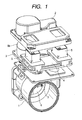
- FIG. 1 shows a decomposition perspective view of the throttle body which is an embodiment of this invention.
- the base 3 is equipped with an airflow sensor (hereinafter abbreviated as AFS) 7, connectors 7 for electric connection to the outside of the throttle body (hereinafter abbreviated as a connector) 5, a throttle position sensor 9b, and a circuit board 4.
- AFS airflow sensor
- connectors 7 for electric connection to the outside of the throttle body hereinafter abbreviated as a connector
- a throttle position sensor 9b a circuit board 4
- This embodiment has two connectors 5.
- One of the connectors 5 (the right connector in FIG. 1) is used to output and input signals required to control the engine such as a accelerator position signal etc..
- the other of the connectors 5 is used to output and input signals for in-car communication and AT shift position information.
- the circuit board 4 on the throttle body is required to be heat resistant as the throttle body is connected to the engine. Therefore, the circuit board 4 is a ceramic board and bonded to the base 3 with a thermosetting resin.
- the throttle position sensor 9b of this embodiment is provided at the base 3, and it is composed with a non-contact type sensor which detects the throttle position magnetically.
- the throttle body for the internal combustion engine (hereinafter abbreviated as a throttle body) is an assembly of the bore body section 1 of throttle body (namely the body of a throttle bore), the base 3, and the cover section 2 of throttle body for covering the base 3 (hereinafter called as cover section 2). They are put on top of each other at the bore body section 1 in order of the base 3, the cover section 2, and are firmly tightened by bolts (not shown in FIG. 1) set in the holes of the components 1, 3, and 2.
- the AFS 7 When the base 3 with the AFS 7 is mounted on the bore body section 1, the AFS 7 is set into bore body section 1 and positioned in the upstream side of the throttle valve 6 (in the near side of FIG. 1).
- the electronic circuit section (mounted on the base 3) is composed as a subassembly of the throttle body.
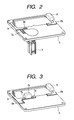
- FIG. 5 shows a perspective view of the electronic circuit section on the base 3 before attaching the connector 5.
- the circuit board 4 with an electronic circuit (not shown in FIG. 5) containing ICs, diodes, etc. is bonded to the base 3 with a thermosetting resin.
- this electronic circuit for controlling the throttle valve also works as an engine control unit (ECU). Therefore, this circuit generates more heat than the electronic circuit for controlling the throttle valve only and becomes very hot.
- ECU engine control unit
- the electric connection section 8 for the airflow sensor 7, the throttle position sensor 9b, and terminals of the throttle-valve driving motor 15 are electrically connected to the electronic circuit respectively with bonding wires 12.
- the components are respectively bonded to the base 3 with adhesives.
- the connectors 5 are connected with the left and right ends of connector base 10 before being mounted on base 3.
- the connector base 10 is different member from base 3.
- the base 3 is put on the connector base 10.
- the circuit board 4 previously mounted on the base 3.
- the connector 5 faces in opposite direction of the state after its mounting (A downward state in Fig. 5).
- the connector pin 101 of each connector 5 is connected to the electronic circuit of the board 4 with a flexible board 11.
- each connector 5 is made turn over inwards (towards the circuit board 4) around the notch 102 which is provided at the ends of connector base 10.
- the positioning projection 103 of the connector fit into the positioning holes (dents) 104 on the base 3, and the connectors 5 are mounted on base 3 with positioning.
- the connector bases 10 are removed from the base 3.
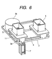
- FIG. 6 shows a perspective view of the base having the connectors thereon. This shows that the two connectors and the circuit board 4 are densely mounted on the base 3 at the state of putting circuit board 4 between the connectors 5.
- the base 3 already has been equipped with the airflow sensor 7 and the throttle position sensor 9b.
- the pins (terminals) of each connector 5 are electrically connected to the electronic circuit on the circuit board 4 with a flexible circuit board 11.
- the corner holes 3d of the base 3 are used to position and carry the base assembly in later assembling.
- the base and the other members are modularized in this way. Mounting various members on a smaller intermediate member (the base here) and then mounting the intermediate member on the throttle valve is much easier in assembling than mounting the members directly on the throttle valve.
- the electronic circuit board of this embodiment uses a heat-resistant ceramic board as it is finally assembled with the throttle body. Further, the non-circuit side of this ceramic board is bonded to the base with a thermosetting resin as it is difficult to attach the ceramic board by screws. When the heat capacity of a member to which the electronic circuit is bonded is small, the heating facility to bond the circuit board can be smaller.
- the circuit board can be bonded to the base with a thermosetting resin in a smaller heating facility than the base is bonded to the member containing the throttle bore.
- the electronic circuit on the base can be efficiently wire-bonded to the base.
- this embodiment assembles various components mainly on the base, which can simplify the assembling procedure. More specifically, this can increase the working ability and efficiency and reduce the manufacturing cost of the throttle body.
- the base 3 has an aperture 3e under the circuit board 4.
- the bore body 1 has a projection 1a for radiating heat of the circuit board 4. This projection 1a is fit into the aperture 3e.
- heat of the circuit board 4 can be transferred through the projection 1a.
- a heat-conductive grease 13 is applied to the surface of the projection 1a which faces the circuit board.
- a heat-radiating sheet instead of the heat-conductive grease 13 can be attached to the surface. This configuration can reduce radiation role of heat through the base 3, and the base 3 can be made of resin. This can reduce the weight of the whole throttle body in comparison with a throttle body using a metallic base.
- This embodiment can provide a throttle body equipped with an ECU and a throttle body whose ECU is fully cooled.
- FIG. 8 shows a perspective view of the completed throttle body.
- the components of this throttle body are similar to those of FIG. 1 and their explanation is omitted.
- FIG. 9 shows the sealing structure of the airflow sensor 7.
- This embodiment requires simultaneous fitting of multiple axes such as connection to motor terminals and insertion of the airflow sensor 7 into the throttle bore body 1. Plays for fitting are provided to increase its working ability.
- an O ring 14 is provided as a seal on the seat which is parallel to the surface of the base instead of the side of the airflow sensor, the hole through which the airflow sensor can be made horizontally wider so that the airflow sensor can be inserted easily.
- Embodiment 2 is almost the same as Embodiment 1 except the following:
- Embodiment 3 is almost the same as Embodiment 1 except the following:
- each embodiment has the base in contact with the body bore part of the throttle body. This can make the wires between the airflow sensor and the circuit board shorter than those when the ECU is provided outside the body bore. Further, this keeps the impedance of the wires low, enables faster output of the APS to the ECU, and thus improves the responsibility.
- control circuit board and sensor circuits are assembled into a small base assembly which is separated from the great throttle body bore and the throttle body cover and the base assembly is finally mounted on the throttle body bore having a high heat capacity in close contact therewith. This can stabilize heat radiation of the circuit board and improve the workability of the throttle body and the ECU.
- the throttle body structure made by assembling the control circuit board and sensor circuits into a small base assembly which is separated from the great throttle body bore and the throttle body cover and finally mounting the base assembly on the throttle body bore having a high heat capacity in close contact therewith can stabilize heat radiation of the circuit board and improve the workability of the throttle body.
- This invention can provide a throttle body and an air intake equipment for an internal combustion engine that can be assembled more easily.
Landscapes
- Engineering & Computer Science (AREA)
- Chemical & Material Sciences (AREA)
- Combustion & Propulsion (AREA)
- Mechanical Engineering (AREA)
- General Engineering & Computer Science (AREA)
- Physics & Mathematics (AREA)
- Fluid Mechanics (AREA)
- Analytical Chemistry (AREA)
- Control Of Throttle Valves Provided In The Intake System Or In The Exhaust System (AREA)
- Electrical Control Of Air Or Fuel Supplied To Internal-Combustion Engine (AREA)
Abstract
Description
Claims (13)
- A throttle body for an internal combustion engine, comprising:wherein an electronic circuit composing said engine control unit is provided at a base (3) which is any other member than the body (hereafter, it is called "bore body") of said throttle bore.an airflow sensor (7) for measuring the flow rate of air passing through a throttle bore,a throttle position sensor (9b) for measuring the opening of a throttle valve (6) in said throttle bore, andan engine control unit for controlling the engine,
- The throttle body for an internal combustion engine according to claim 1, wherein said base (3) has terminals which are electrically connected to at least any of a motor (15) for driving said throttle valve (6), said airflow sensor (7), and said throttle position sensor (9b).
- The throttle body for an internal combustion engine according to claim 1 or 2, wherein at least one of said airflow sensor (7) and said throttle position sensor (9b) is provided at said base (3).
- The throttle body for an internal combustion engine according to at least one of claims 1 to 3, wherein at least one part of the base area which mounts said electronic circuit has at least one aperture (3e), and said electronic circuit is in contact with said bore body through said aperture.
- The throttle body for an internal combustion engine according to at least one of claims 1 to 4, wherein the area on which said electronic circuit is in contact with said throttle bore body is greased.
- The throttle body for an internal combustion engine according to at least one of claims 1 to 5, wherein said throttle body has at least one projection (1a) which is set in said aperture (3e).
- A throttle body for an internal combustion engine, comprising:wherein an electronic circuit which composes said engine control unit is mounted on a base (3) which is any other member than said bore body containing said throttle bore; said throttle body, the base of said electronic base, and said throttle body cover (2) are located in that order by tightening with screws.an airflow sensor (7) for measuring at least one of the flow rate and the velocity of air passing through a throttle bore provided in the bore body,a throttle position sensor (9b) for measuring the opening of a motor-driven throttle valve (6) in said throttle bore,an engine control unit for controlling the engine,and a throttle cover (2) for covering said engine control unit,
- The throttle body for an internal combustion engine according to claim 7, wherein said base (3) has connectors (5) for connecting said electronic circuit to an external circuit.
- The throttle body for an internal combustion engine according to claims 7 or 8, wherein said connector (5) is guided to outside of said throttle body through a hole formed at said throttle body cover (2) from a space formed by said bore body and said throttle body cover (2), and connected with an outer electric section.
- The throttle body for an internal combustion engine according to at least one of claims 7 to 9, wherein said base (3) has at least two connectors (5) of which has terminals for inputting and outputting engine controlling signals and the other has terminals for inputting and outputting at least one of AT (automatic) shift information and in-car communication.
- The throttle body for an internal combustion engine according to at least one of claims 7 to 10, wherein said connector (5) is mounted on said base (3) so that a projection provided at said connector may be fitted to a recess on said base (3), or a recess provided at said connector (5) may be fitted to a projection on said base (3).
- The throttle body for an internal combustion engine according to at least one of claims 7 to 11, wherein said throttle valve (6) is driven by a motor (15) provided on said bore body.
- A throttle body for an internal combustion engine, comprising:wherein a part of said airflow sensor (7) contacts with said bore body and sealed thereon hermetically in the axial direction of airflow sensor (7) by pressing said airflow sensor (7) against said bore body.an airflow sensor (7) for measuring at least one of the flow rate and the velocity of air passing through a throttle bore provided in the bore body,a throttle position sensor (9b) for measuring the opening of a motor-driven throttle valve (6) in said throttle bore,an engine control unit for controlling the engine,and a throttle cover (2) for covering said engine control unit,
Applications Claiming Priority (2)
| Application Number | Priority Date | Filing Date | Title |
|---|---|---|---|
| JP2002340232A JP4000994B2 (en) | 2002-11-25 | 2002-11-25 | Throttle body and intake device for internal combustion engine |
| JP2002340232 | 2002-11-25 |
Publications (2)
| Publication Number | Publication Date |
|---|---|
| EP1422405A2 true EP1422405A2 (en) | 2004-05-26 |
| EP1422405A3 EP1422405A3 (en) | 2008-03-05 |
Family
ID=32212148
Family Applications (1)
| Application Number | Title | Priority Date | Filing Date |
|---|---|---|---|
| EP03026940A Withdrawn EP1422405A3 (en) | 2002-11-25 | 2003-11-25 | Throttle body and air intake equipment for internal combustion engine |
Country Status (3)
| Country | Link |
|---|---|
| US (1) | US6892699B2 (en) |
| EP (1) | EP1422405A3 (en) |
| JP (1) | JP4000994B2 (en) |
Cited By (4)
| Publication number | Priority date | Publication date | Assignee | Title |
|---|---|---|---|---|
| WO2011110447A1 (en) * | 2010-03-12 | 2011-09-15 | Robert Bosch Gmbh | Arrangement of an engine control unit on an internal combustion engine and engine system |
| EP2940285A1 (en) * | 2014-05-01 | 2015-11-04 | JC Bamford Excavators Ltd | An air inlet system |
| DE102014213324A1 (en) * | 2014-07-09 | 2016-01-14 | Zf Friedrichshafen Ag | Electromechanical actuator |
| EP3354891A1 (en) * | 2017-01-26 | 2018-08-01 | MAN Truck & Bus AG | Device for mounting a control unit at an internal combustion engine |
Families Citing this family (14)
| Publication number | Priority date | Publication date | Assignee | Title |
|---|---|---|---|---|
| JP4000994B2 (en) * | 2002-11-25 | 2007-10-31 | 株式会社日立製作所 | Throttle body and intake device for internal combustion engine |
| MX2007010194A (en) * | 2004-09-10 | 2008-11-04 | Knorr Bremse Systeme | "torque deficiency" (accumulator-based charge assistance). |
| JP2006097500A (en) * | 2004-09-28 | 2006-04-13 | Honda Motor Co Ltd | General-purpose engine throttle device |
| US20070040143A1 (en) * | 2005-08-18 | 2007-02-22 | Garrick Robert D | Throttle passage whistling control device and method |
| JP5479239B2 (en) * | 2010-06-22 | 2014-04-23 | 本田技研工業株式会社 | ECU integrated throttle device |
| JP5335749B2 (en) * | 2010-09-28 | 2013-11-06 | 本田技研工業株式会社 | Engine control device |
| DE102010050322B4 (en) * | 2010-11-05 | 2014-03-27 | Pierburg Gmbh | Exhaust control device for an internal combustion engine |
| US20120240898A1 (en) * | 2011-03-23 | 2012-09-27 | Visteon Global Technologies, Inc. | Integrated plastic throttle body, electronic control unit, and sensors for small engine |
| JP2013064367A (en) * | 2011-09-20 | 2013-04-11 | Hitachi Automotive Systems Ltd | Air physical quantity detector |
| JP5731430B2 (en) * | 2012-03-15 | 2015-06-10 | 株式会社Ihiシバウラ | Engine control device |
| JP6048069B2 (en) * | 2012-10-25 | 2016-12-21 | トヨタ自動車株式会社 | Crankcase |
| JP5987877B2 (en) * | 2013-10-04 | 2016-09-07 | 株式会社デンソー | Electronic throttle |
| JP1735274S (en) * | 2022-05-30 | 2023-01-24 | Throttle body for internal combustion engine | |
| JP1735276S (en) * | 2022-06-06 | 2023-01-24 | Throttle body for internal combustion engine |
Family Cites Families (22)
| Publication number | Priority date | Publication date | Assignee | Title |
|---|---|---|---|---|
| FR2439388A1 (en) * | 1978-10-20 | 1980-05-16 | Bosch Gmbh Robert | INSTALLATION FOR MEASURING THE MASS OF A FLOWING FLUID |
| JPS5722563A (en) * | 1980-07-15 | 1982-02-05 | Hitachi Ltd | Sucked air flowmeter for internal combustion engine |
| KR950009044B1 (en) * | 1987-06-17 | 1995-08-14 | 가부시키가이샤 히타치세이사쿠쇼 | Hot-wire type air flow meter and an internal combustion engine with the same |
| EP0441523B2 (en) * | 1990-02-07 | 2001-05-09 | Hitachi, Ltd. | Air flow rate measuring device for an internal combustion engine |
| DE4430324C1 (en) * | 1994-08-26 | 1996-10-10 | Vdo Schindling | Air intake pipe for automobile i.c. engine |
| US5711271A (en) * | 1995-05-05 | 1998-01-27 | Robert Bosch Gmbh | Throttle apparatus for an internal combustion engine |
| JP3323745B2 (en) * | 1996-07-25 | 2002-09-09 | 株式会社日立製作所 | Characteristic adjustment means of physical quantity detection device and heating resistance type air flow device |
| JP3404254B2 (en) * | 1997-05-07 | 2003-05-06 | 株式会社日立製作所 | Engine throttle device |
| US6427668B1 (en) * | 1997-06-26 | 2002-08-06 | Hitachi, Ltd. | Thermal-type airflow meter, intake air system for an internal combustion engine, and control system for the same |
| JPH11264332A (en) * | 1997-12-17 | 1999-09-28 | Hitachi Ltd | Air flow meter with electronically controlled throttle body |
| US5988119A (en) * | 1998-08-03 | 1999-11-23 | Ford Motor Company | Electronic control module assembly using throttle body air for cooling and method thereof |
| JP2000130187A (en) | 1998-10-27 | 2000-05-09 | Keihin Corp | Engine intake air control system |
| EP1167724B1 (en) * | 1999-03-29 | 2004-05-26 | Hitachi, Ltd. | Electronically controlled throttle device |
| US6494186B1 (en) * | 1999-09-30 | 2002-12-17 | Siemens Vdo Automotive Corporation | Integral engine control sensor |
| US6497245B1 (en) * | 1999-10-13 | 2002-12-24 | Denso Corporation | Intake air controller for internal combustion engine and manufacturing the same |
| JP2002122452A (en) * | 2000-08-11 | 2002-04-26 | Ngk Spark Plug Co Ltd | Split flow meter |
| US6522038B2 (en) * | 2000-12-15 | 2003-02-18 | Delphi Technologies, Inc. | Integrated air control valve using contactless technology |
| DE10117542A1 (en) * | 2001-04-07 | 2002-10-10 | Siemens Ag | Throttle body and electronics module |
| JP4794769B2 (en) * | 2001-08-02 | 2011-10-19 | 株式会社ミクニ | Engine control device, ECU (Electronic Control Unit) and ECU case |
| US6622555B2 (en) * | 2001-10-11 | 2003-09-23 | Visteon Global Technologies, Inc. | Fluid flow meter |
| JP3817497B2 (en) * | 2002-06-10 | 2006-09-06 | 株式会社日立製作所 | Thermal flow meter |
| JP4000994B2 (en) * | 2002-11-25 | 2007-10-31 | 株式会社日立製作所 | Throttle body and intake device for internal combustion engine |
-
2002
- 2002-11-25 JP JP2002340232A patent/JP4000994B2/en not_active Expired - Fee Related
-
2003
- 2003-11-25 US US10/720,482 patent/US6892699B2/en not_active Expired - Fee Related
- 2003-11-25 EP EP03026940A patent/EP1422405A3/en not_active Withdrawn
Cited By (10)
| Publication number | Priority date | Publication date | Assignee | Title |
|---|---|---|---|---|
| WO2011110447A1 (en) * | 2010-03-12 | 2011-09-15 | Robert Bosch Gmbh | Arrangement of an engine control unit on an internal combustion engine and engine system |
| EP2940285A1 (en) * | 2014-05-01 | 2015-11-04 | JC Bamford Excavators Ltd | An air inlet system |
| CN105020068A (en) * | 2014-05-01 | 2015-11-04 | J.C.班福德挖掘机有限公司 | Air intake system |
| US10519903B2 (en) | 2014-05-01 | 2019-12-31 | Jc Bamford Excavators Limited | Air inlet system |
| DE102014213324A1 (en) * | 2014-07-09 | 2016-01-14 | Zf Friedrichshafen Ag | Electromechanical actuator |
| EP3354891A1 (en) * | 2017-01-26 | 2018-08-01 | MAN Truck & Bus AG | Device for mounting a control unit at an internal combustion engine |
| CN108468595A (en) * | 2017-01-26 | 2018-08-31 | 曼卡车和巴士股份公司 | Device for controller being placed on internal combustion engine |
| US10648432B2 (en) * | 2017-01-26 | 2020-05-12 | Man Truck & Bus Ag | Device for attaching a control unit to an internal combustion engine |
| RU2752369C2 (en) * | 2017-01-26 | 2021-07-26 | Ман Трак Унд Бас Аг | Device for placing a control unit on an internal combustion engine |
| CN108468595B (en) * | 2017-01-26 | 2022-07-01 | 曼卡车和巴士股份公司 | Device for mounting a control unit on an internal combustion engine |
Also Published As
| Publication number | Publication date |
|---|---|
| JP4000994B2 (en) | 2007-10-31 |
| JP2004176547A (en) | 2004-06-24 |
| EP1422405A3 (en) | 2008-03-05 |
| US20040154588A1 (en) | 2004-08-12 |
| US6892699B2 (en) | 2005-05-17 |
Similar Documents
| Publication | Publication Date | Title |
|---|---|---|
| US6892699B2 (en) | Throttle body and air intake equipment for internal combustion engine | |
| US7934312B2 (en) | Production method of an electronic circuit device | |
| US10829064B2 (en) | Electronic control device | |
| US7495183B2 (en) | Electronic circuit apparatus | |
| JP2004281722A (en) | Electronic circuit device and method of manufacturing the same | |
| EP1489339A1 (en) | Control device with shift position detector, and power train with the control device | |
| US6683789B1 (en) | Electronic control module for a removable connector and methods of assembling same | |
| CN105027363B (en) | The connection method of circuit fixed component, circuit module and circuit module | |
| KR100352093B1 (en) | Electric circuit device of automobile | |
| EP1342909B1 (en) | Control circuit module, intake air passage body, engine electronic control device, and engine air intake system provided with the same | |
| CN101363368B (en) | Integration unit of air control shutter and controller and method for manufacturing same | |
| US6937462B2 (en) | Electronic control device and manufacturing method for the same | |
| US8526196B2 (en) | Method for receiving an electric/electronic component and corresponding mounting method and covering for said type of device | |
| US6808422B2 (en) | Filter insert for an electrical connector assembly | |
| JP3587425B2 (en) | Intake system control device for internal combustion engine | |
| JP6952804B2 (en) | Electronic components and their manufacturing methods | |
| JP2001282303A (en) | Electronic control device and method of manufacturing the same | |
| JP2002285866A (en) | Throttle device and method of manufacturing the same | |
| JP2002532911A (en) | Electronic control unit | |
| US5922991A (en) | Arrangement for mounting a wiring harness on a support plate | |
| JP2003322043A (en) | Electrical connection structure of parts, ECU (Electronic Control Unit), and engine control device | |
| JP2001267022A (en) | Electronic control unit | |
| JP2001151045A (en) | Automotive electrical circuit equipment | |
| JP2651967B2 (en) | Semiconductor pressure sensor | |
| JP2003239784A (en) | Automotive electrical circuit equipment |
Legal Events
| Date | Code | Title | Description |
|---|---|---|---|
| PUAI | Public reference made under article 153(3) epc to a published international application that has entered the european phase |
Free format text: ORIGINAL CODE: 0009012 |
|
| AK | Designated contracting states |
Kind code of ref document: A2 Designated state(s): AT BE BG CH CY CZ DE DK EE ES FI FR GB GR HU IE IT LI LU MC NL PT RO SE SI SK TR |
|
| AX | Request for extension of the european patent |
Extension state: AL LT LV MK |
|
| PUAL | Search report despatched |
Free format text: ORIGINAL CODE: 0009013 |
|
| AK | Designated contracting states |
Kind code of ref document: A3 Designated state(s): AT BE BG CH CY CZ DE DK EE ES FI FR GB GR HU IE IT LI LU MC NL PT RO SE SI SK TR |
|
| AX | Request for extension of the european patent |
Extension state: AL LT LV MK |
|
| RIC1 | Information provided on ipc code assigned before grant |
Ipc: F02D 11/10 20060101ALI20080131BHEP Ipc: F02D 9/10 20060101AFI20040220BHEP |
|
| RIN1 | Information on inventor provided before grant (corrected) |
Inventor name: URUSHIWARA, NORIYOSHIH |
|
| 17P | Request for examination filed |
Effective date: 20080331 |
|
| RAP1 | Party data changed (applicant data changed or rights of an application transferred) |
Owner name: HITACHI, LTD. |
|
| 17Q | First examination report despatched |
Effective date: 20080610 |
|
| AKX | Designation fees paid |
Designated state(s): DE FR GB IT |
|
| STAA | Information on the status of an ep patent application or granted ep patent |
Free format text: STATUS: THE APPLICATION IS DEEMED TO BE WITHDRAWN |
|
| 18D | Application deemed to be withdrawn |
Effective date: 20081223 |