EP1422095A2 - Window channel covering structure - Google Patents
Window channel covering structure Download PDFInfo
- Publication number
- EP1422095A2 EP1422095A2 EP03025287A EP03025287A EP1422095A2 EP 1422095 A2 EP1422095 A2 EP 1422095A2 EP 03025287 A EP03025287 A EP 03025287A EP 03025287 A EP03025287 A EP 03025287A EP 1422095 A2 EP1422095 A2 EP 1422095A2
- Authority
- EP
- European Patent Office
- Prior art keywords
- window
- sealing element
- covering device
- strip
- channel strip
- Prior art date
- Legal status (The legal status is an assumption and is not a legal conclusion. Google has not performed a legal analysis and makes no representation as to the accuracy of the status listed.)
- Granted
Links
Images


Classifications
-
- B—PERFORMING OPERATIONS; TRANSPORTING
- B60—VEHICLES IN GENERAL
- B60J—WINDOWS, WINDSCREENS, NON-FIXED ROOFS, DOORS, OR SIMILAR DEVICES FOR VEHICLES; REMOVABLE EXTERNAL PROTECTIVE COVERINGS SPECIALLY ADAPTED FOR VEHICLES
- B60J5/00—Doors
- B60J5/04—Doors arranged at the vehicle sides
- B60J5/0401—Upper door structure
- B60J5/0402—Upper door structure window frame details, including sash guides and glass runs
-
- B—PERFORMING OPERATIONS; TRANSPORTING
- B60—VEHICLES IN GENERAL
- B60J—WINDOWS, WINDSCREENS, NON-FIXED ROOFS, DOORS, OR SIMILAR DEVICES FOR VEHICLES; REMOVABLE EXTERNAL PROTECTIVE COVERINGS SPECIALLY ADAPTED FOR VEHICLES
- B60J1/00—Windows; Windscreens; Accessories therefor
- B60J1/08—Windows; Windscreens; Accessories therefor arranged at vehicle sides
- B60J1/12—Windows; Windscreens; Accessories therefor arranged at vehicle sides adjustable
- B60J1/16—Windows; Windscreens; Accessories therefor arranged at vehicle sides adjustable slidable
- B60J1/17—Windows; Windscreens; Accessories therefor arranged at vehicle sides adjustable slidable vertically
-
- B—PERFORMING OPERATIONS; TRANSPORTING
- B60—VEHICLES IN GENERAL
- B60J—WINDOWS, WINDSCREENS, NON-FIXED ROOFS, DOORS, OR SIMILAR DEVICES FOR VEHICLES; REMOVABLE EXTERNAL PROTECTIVE COVERINGS SPECIALLY ADAPTED FOR VEHICLES
- B60J10/00—Sealing arrangements
- B60J10/70—Sealing arrangements specially adapted for windows or windscreens
- B60J10/74—Sealing arrangements specially adapted for windows or windscreens for sliding window panes, e.g. sash guides
- B60J10/75—Sealing arrangements specially adapted for windows or windscreens for sliding window panes, e.g. sash guides for sealing the lower part of the panes
-
- B—PERFORMING OPERATIONS; TRANSPORTING
- B60—VEHICLES IN GENERAL
- B60J—WINDOWS, WINDSCREENS, NON-FIXED ROOFS, DOORS, OR SIMILAR DEVICES FOR VEHICLES; REMOVABLE EXTERNAL PROTECTIVE COVERINGS SPECIALLY ADAPTED FOR VEHICLES
- B60J5/00—Doors
- B60J5/04—Doors arranged at the vehicle sides
- B60J5/0411—Beltline
Definitions
- the invention relates to a window slot cover for vehicle windows, in particular on Vehicle doors, with a profiled window molding, in the at least one attachment portion an elastic window pane sealing element is included.
- window cover devices are in vehicles, in particular on doors of motor vehicles, known.
- the window slot bar is at the top of a window slot outside a vehicle door arranged, wherein the window shaft picks up the glass when this is to Shutting down the vehicle window is shut down.
- the window slot strip takes at least one attachment section an elastic window pane sealing element on, on the windowpane is applied and penetration of dirt and moisture largely prevented in the window slot.
- the window slot cover device exists at the end of the window slot bar the Disadvantage that the window glass sealing rubber the Interior of the profiled window channel strip not completely filled and therefore sharp-edged Zones, in particular border areas, the window channel strip, preferably made of metal, in particular Made of aluminum, there is a risk of injury for the users of the vehicle.
- the window slot cover device the vehicle door in direction surmounted by the so-called B-pillar of the vehicle and thus forms a projection on the door.
- this projection of the B-pillar leads to a continuous image in the course of the window channel strip, that is, it extends over the entire front door of the vehicle and part over the B-pillar.
- each of the two window slots of the front and back door covers the B-pillar about halfway, so that between these two only a small one Parting line exists and the visual impression a continuous window channel strip is created.
- the object of the invention is therefore to provide a window slot covering device to create that no Risk of injury and also brings one has high manufacturing and quality standards.
- This object is achieved by a, in a strip end, between the window pane sealing element and window slot rail trained Free space inserted filler.
- This Filler leads to the window channel strip inside its profiled shape end without training a free space or only a very small clearance is designed as this Free space of said filler at least partially or completely filled.
- the result is that the filler any sharp-edged Edge areas and corner areas of the window channel strip covering or brought to these zones is, so that in particular at a touch of Window slot strip from the rear no risk of injury consists. This touch from behind is particular then possible if the window channel strip protrudes over the vehicle door and the Vehicle door is in the open state.
- the filler piece on the window channel strip is attached. This ensures the captivity, wherein the attachment as latching attachment and / or Clamping and / or adhesive attachment trained can be.
- the window slot strip a has end end wall, and that the filler at least in the space between the front wall and the associated end of the windowpane sealing element, in particular the end of a sealing lip arrangement the windowpane sealing element, is arranged.
- the window channel strip a retaining tab for the window pane sealing element and that the retaining tab the Hold the filler piece or hold it with it.
- the elastic Window glass sealing element is preferably made of rubber or rubber-like material and gets trapped in the window slot. It may have a metal insert.
- For clamping bracket which can be supported by gluing, serves the said retaining tab. It can about the Length of the window slot strip also several retaining tabs be provided. Preferably, this takes over Retaining tab another holding function by not just holding the window-glass sealing element, but also the filler.
- the filler a Has free cut, that is shaped so that in the free cut the retaining tab is added, without the retaining tab a holding effect on the Filler unfolded. This is especially the case Case when the filler in the window channel strip is glued.
- the lower corner area of the window channel strip inside of the filler or a section from this to the education of an injury protection is covered.
- the lower corner area of a protruding Window channel strip due to the invention Filler so inside the Window slot bar is covered or attached to the Filler protrudes such that the edge region and the corner of the sheet-like window channel strip no longer sharp-edged protrudes.
- FIG. 1 shows a vehicle door 1 of a vehicle, in particular of a motor vehicle having a retractable window pane 2 and a sheet metal door leaf 3 has.
- the transition zone 4 between Window 2 and sheet metal door leaf 3 is -von the outside by means of a window slot covering device 5 covered.
- the window slot covering device 5 has a Brechachtance 6, which is profiled, off Metal, in particular aluminum, and consists over the entire longitudinal extent of the vehicle door extends.
- the Window 2 has a smaller width than that Sheet metal door leaf 3, surmounting the window slot covering device 5 the window pane 2 to a measure x, whereby -in the open door- a risk of injury Corner zone 7 is formed.
- a window pane sealing element 8 assigned such that this -aus elastic material consisting between window channel strip 6 and window 2 and is doing more or less sealing on the surface the window pane 2 is applied to the penetration of Moisture and dirt in the interior of the sheet metal door leaf 3, in particular in the trained there Window slot, to prevent.
- the corner zone 7 in a view from below and behind, so from the passenger compartment out, shows, it becomes clear that the window molding 6 profile-like, like a C-profile, is configured and end an end wall. 9 having. This has about a triangular shape.
- a retaining tab 11 At the lower edge 10 of the window slot 6 is located a retaining tab 11, which is not up to the End wall 9 extends, but thereof a distance a has.
- the retaining tab 11, the one-piece is formed on the window channel strip 6, serves to receive the window-sealing element 8 and to hold.
- the window pane sealing element 8 a fixing section 12, preferably behind the retaining tab 11th snapped or pinched there.
- the window channel strip 6 is hook-shaped designed and engages behind the attachment section 12. Furthermore, has the windowpane sealing element 8 multiple sealing lips 13 to the plant on the window pane 2.
- the window-pane sealing element is sufficient 8, in particular its attachment portion 12, do not end up to the end Edge 10 and not even to the front wall 9, so that a free space 14 is formed in these zones is.
- the inner corner zone 15 of Novachachtance 6 completely exposed and therefore through the mostly relatively sharp-edged edge and the exposed position injurious to injury, the means, in particular, outgoing persons can Hook behind this zone and injure yourself.
- the invention provides that the attachment portion 12 is not up to the height the front ends 18 of the sealing lips 13 extends, but that between the mentioned elements Return b exists. This has the consequence that the attachment portion 12 not to the end edge 16 of the retaining tab 11 extends, but that there a distance c exists. Also in this respect is enough Free space 14 so into this zone of length c inside.
- the rear Interior of the profile-like window slot 6 in the corner zone 7 is preferably made of plastic finished, elastic or not elastic Filler 17 provided according to Figure 3, the on the one hand, the distance between the front ends 18th the sealing lips 13 of the window-glass sealing element 8 and the inside of the end wall. 9 fills and further extends into the corner zone 15, where there is the course of the end wall. 9 until the end edge 16 of the retaining tab 11 takes place.
- the filling piece 17 has a region 19, the retaining tab 11 overlaps, so that so the entire, trained there free space 14 at least partly, but in any case so that no risk of injury at the relatively sharp-edged edges the window shaft strip 6 is filled out is.
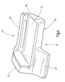
- FIG. 4 shows a perspective view of a Filler 17, as can be seen in Figure 3 is.
- the filler 17 has a bottom 20 on, the C-profile-like shape the window slot bar 6 is adjusted. It owns Furthermore, a free punch 21, the one of Tongue 22 is projected forward.
- the free cut 21 serves - according to Figure 3- to accommodate the Retaining tab 11, that is, the filler 17 of the figure 4 is not held by the retaining tab 11.
- the filling piece 17 On the edge side, the filling piece 17 has a filling wall 23 which, in the inserted state according to FIG the area of the free space 14 intervenes, the between the end wall 18 of the sealing lips 13 and the Inside the front wall 9 of the window slot strip 6 lies.
- the tongue 22 fills the corner zone 15.
- One Basic body region 24 of the filling piece 17 of FIG. 4 engages in an area of open space 14, between the window channel strip 6 and the sealing lips 13 lies. Furthermore, the body region adjoins 24 with its end face 25 to the corresponding Front side of the attachment portion 12 at. With a holding web 26 extending from the body region 24 goes out to the top and with the filling wall 23rd is connected, there is a rear grip on the back the sealing lips 13. Overall, it is clear that the filler 17 safely and accordingly randabshowd on the window channel strip 6 fastened is.
- For the attachment can be a bond and / or detent and / or clamping provided be.
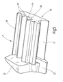
- FIG. 5 shows a further exemplary embodiment a filler 17, which is designed substantially so is like the filler piece according to the embodiment of Figure 4. It should therefore only below to discuss the differences.
- the filler 17 of Figure 5 has no free punch 21, but in its place a fixing tongue 27th on, in the inserted state behind the retaining tab 11 attacks and therefore the attachment of the Filler 17 on the window channel strip 6 is used.
- the width of the tongue 22 in the embodiment of Figure 5 smaller than in the embodiment the figure 4. This has the consequence that the retaining tab 11 to close to the front wall 9 of the window shaft strip 6 extend zoom can.
- the base body region 24 its top profile ribs 28 on, the one corresponding profiling on the attachment section 12 of the window-sealing element 8 correspond.
- the insertion of the filler 17 of the figure 5 takes place in a similar manner as the insertion of the filler 17 of Figure 4, but wherein the fastening tongue 27 acted upon by the retaining tab 11 is and therefore ensures an extremely secure grip becomes.
Landscapes
- Engineering & Computer Science (AREA)
- Mechanical Engineering (AREA)
- Window Of Vehicle (AREA)
- Seal Device For Vehicle (AREA)
- Air Bags (AREA)
- Helmets And Other Head Coverings (AREA)
- Fish Paste Products (AREA)
- Rear-View Mirror Devices That Are Mounted On The Exterior Of The Vehicle (AREA)
Abstract
Description
Die Erfindung betrifft eine Fensterschacht-Abdeckung für Fahrzeugfenster, insbesondere an Fahrzeugtüren, mit einer profilierten Fensterschachtleiste, in der zumindest ein Befestigungsabschnitt eines elastischen Fensterscheiben-Dichtelements aufgenommen ist.The invention relates to a window slot cover for vehicle windows, in particular on Vehicle doors, with a profiled window molding, in the at least one attachment portion an elastic window pane sealing element is included.
Derartige Fensterschacht-Abdeckvorrichtungen sind bei Fahrzeugen, insbesondere an Türen von Kraftfahrzeugen, bekannt. Die Fensterschachtleiste ist im oberen Bereich eines Fensterschachts außen an einer Fahrzeugtür angeordnet, wobei der Fensterschacht die Glasscheibe aufnimmt, wenn diese zum Öffnen des Fahrzeugfensters heruntergefahren wird. Die Fensterschachtleiste nimmt zumindest einen Befestigungsabschnitt eines elastischen Fensterscheiben-Dichtelements auf, das an der Fensterscheibe anliegt und ein Eindringen von Schmutz und Feuchtigkeit in den Fensterschacht weitestgehend verhindert.Such window cover devices are in vehicles, in particular on doors of motor vehicles, known. The window slot bar is at the top of a window slot outside a vehicle door arranged, wherein the window shaft picks up the glass when this is to Shutting down the vehicle window is shut down. The window slot strip takes at least one attachment section an elastic window pane sealing element on, on the windowpane is applied and penetration of dirt and moisture largely prevented in the window slot.
Bei der bekannten Fensterschacht-Abdeckvorrichtung besteht endseitig der Fensterschachtleiste der Nachteil, dass das Fensterscheiben-Dichtgummi das Innere der profilierten Fensterschachtleiste nicht vollständig ausfüllt und demzufolge scharfkantige Zonen, insbesondere Randbereiche, der Fensterschachtleiste, die vorzugsweise aus Metall, insbesondere aus Aluminium, besteht eine Verletzungsgefahr für die Benutzer des Fahrzeugs bilden. Dies ist insbesondere dann gegeben, wenn die Fensterschacht-Abdeckvorrichtung die Fahrzeugtür in Richtung der sogenannten B-Säule des Fahrzeugs überragt und demzufolge einen Vorsprung an der Tür bildet. Dieses Überragen der B-Säule führt zwar zu einem durchgehenden Bild bei dem Verlauf der Fensterschachtleiste, das heißt, sie erstreckt sich über die gesamte Vordertür des Fahrzeugs und ein Teil über die B-Säule. Bei der hinteren Tür (Fondtür) überragt die Fensterschachtleiste die Tür im Scharnierbereich, um die genannte B-Säule ebenfalls teilweise abzudecken. Vorzugsweise ist vorgesehen, dass jede der beiden Fensterschachtleisten der Vorder- und Hintertür die B-Säule etwa hälftig abdeckt, so dass zwischen diesen beiden nur eine geringe Trennfuge besteht und der optische Eindruck einer durchlaufenden Fensterschachtleiste entsteht.In the known window slot cover device exists at the end of the window slot bar the Disadvantage that the window glass sealing rubber the Interior of the profiled window channel strip not completely filled and therefore sharp-edged Zones, in particular border areas, the window channel strip, preferably made of metal, in particular Made of aluminum, there is a risk of injury for the users of the vehicle. This is particularly given when the window slot cover device the vehicle door in direction surmounted by the so-called B-pillar of the vehicle and thus forms a projection on the door. Although this projection of the B-pillar leads to a continuous image in the course of the window channel strip, that is, it extends over the entire front door of the vehicle and part over the B-pillar. At the rear door (rear door) the window slot strip projects beyond the door in the hinge area, also around said B-pillar partially cover. It is preferably provided that each of the two window slots of the front and back door covers the B-pillar about halfway, so that between these two only a small one Parting line exists and the visual impression a continuous window channel strip is created.
Aufgabe der Erfindung ist es daher, eine Fensterschacht-Abdeckvorrichtung zu schaffen, die keine Verletzungsgefahr mit sich bringt und ferner einen hohen Fertigungs- und Qualitätsstandard besitzt.The object of the invention is therefore to provide a window slot covering device to create that no Risk of injury and also brings one has high manufacturing and quality standards.
Diese Aufgabe wird erfindungsgemäß gelöst durch ein, in einen leistenendseitigen, zwischen Fensterscheiben-Dichtelement und Fensterschachtleiste ausgebildeten Freiraum eingesetztes Füllstück. Dieses Füllstück führt dazu, dass die Fensterschachtleiste im Innern ihrer profilierten Formgebung endseitig ohne Ausbildung eines Freiraums oder nur eines sehr geringen Freiraums ausgestaltet ist, da dieser Freiraum von dem genannten Füllstück zumindest teilweise oder vollständig aufgefüllt wird. Die Folge ist, dass das Füllstück etwaige scharfkantige Randbereiche und Eckbereiche der Fensterschachtleiste abdeckt oder bis an diese Zonen herangeführt ist, so dass insbesondere bei einer Berührung der Fensterschachtleiste von hinten keine Verletzungsgefahr besteht. Diese Berührung von hinten ist insbesondere dann möglich, wenn die Fensterschachtleiste über die Fahrzeugtür hinausragt und sich die Fahrzeugtür im geöffneten Zustand befindet.This object is achieved by a, in a strip end, between the window pane sealing element and window slot rail trained Free space inserted filler. This Filler leads to the window channel strip inside its profiled shape end without training a free space or only a very small clearance is designed as this Free space of said filler at least partially or completely filled. The The result is that the filler any sharp-edged Edge areas and corner areas of the window channel strip covering or brought to these zones is, so that in particular at a touch of Window slot strip from the rear no risk of injury consists. This touch from behind is particular then possible if the window channel strip protrudes over the vehicle door and the Vehicle door is in the open state.
Nach einer Weiterbildung der Erfindung ist vorgesehen, dass das Füllstück an der Fensterschachtleiste befestigt ist. Dieses sichert die Unverlierbarkeit, wobei die Befestigung als Rastbefestigung und/oder Klemmbefestigung und/oder Klebebefestigung ausgebildet sein kann.According to a development of the invention is provided that the filler piece on the window channel strip is attached. This ensures the captivity, wherein the attachment as latching attachment and / or Clamping and / or adhesive attachment trained can be.
Nach einer weiteren Ausführungsform der Erfindung ist vorgesehen, dass die Fensterschachtleiste eine endseitige Stirnwand aufweist, und dass das Füllstück zumindest im Freiraum zwischen der Stirnwand und dem zugeordneten Ende des Fensterscheiben-Dichtelements, insbesondere dem Ende einer Dichtlippenanordnung des Fensterscheibendichtelements, angeordnet ist.According to a further embodiment of the invention is provided that the window slot strip a has end end wall, and that the filler at least in the space between the front wall and the associated end of the windowpane sealing element, in particular the end of a sealing lip arrangement the windowpane sealing element, is arranged.
Ferner ist es vorteilhaft, wenn die Fensterschachtleiste eine Haltelasche für das Fensterscheiben-Dichtelement aufweist und dass die Haltelasche das Füllstück festhält oder mit festhält. Das elastische Fensterscheiben-Dichtelement besteht vorzugsweise aus Gummi oder gummiähnlichem Material und wird in der Fensterschachtleiste eingeklemmt. Es kann eine Metalleinlage aufweisen. Zur Klemmhalterung, die durch Klebung unterstützt sein kann, dient die genannte Haltelasche. Es können über die Länge der Fensterschachtleiste auch mehrere Haltelaschen vorgesehen sein. Bevorzugt übernimmt diese Haltelasche eine weitere Haltefunktion, indem sie nicht nur das Fensterscheiben-Dichtelement hält, sondern auch das Füllstück. Alternativ kann jedoch auch vorgesehen sein, dass das Füllstück einen Freischnitt aufweist, also so geformt ist, dass in dem Freischnitt die Haltelasche aufgenommen wird, ohne dass die Haltelasche eine Haltewirkung auf das Füllstück entfaltet. Dies ist insbesondere dann der Fall, wenn das Füllstück in die Fensterschachtleiste eingeklebt wird.Furthermore, it is advantageous if the window channel strip a retaining tab for the window pane sealing element and that the retaining tab the Hold the filler piece or hold it with it. The elastic Window glass sealing element is preferably made of rubber or rubber-like material and gets trapped in the window slot. It may have a metal insert. For clamping bracket, which can be supported by gluing, serves the said retaining tab. It can about the Length of the window slot strip also several retaining tabs be provided. Preferably, this takes over Retaining tab another holding function by not just holding the window-glass sealing element, but also the filler. Alternatively, however, can Also be provided that the filler a Has free cut, that is shaped so that in the free cut the retaining tab is added, without the retaining tab a holding effect on the Filler unfolded. This is especially the case Case when the filler in the window channel strip is glued.
Nach einer bevorzugten Ausführungsform ist vorgesehen, dass der untere Eckbereich der Fensterschachtleiste innenseitig von dem Füllstück oder einem Abschnitt von diesem zur Ausbildung eines Verletzungsschutzes abgedeckt ist. Besonders verletzungsgefährdend ist der untere Eckbereich einer vorstehenden Fensterschachtleiste, der aufgrund des erfindungsgemäßen Füllstückes derart im Innern der Fensterschachtleiste abgedeckt wird oder an den das Füllstück derart heranragt, dass der Randbereich und der Eckbereich der blechartigen Fensterschachtleiste nicht mehr scharfkantig vorsteht.According to a preferred embodiment, it is provided that the lower corner area of the window channel strip inside of the filler or a section from this to the education of an injury protection is covered. Especially injurious to injury is the lower corner area of a protruding Window channel strip, due to the invention Filler so inside the Window slot bar is covered or attached to the Filler protrudes such that the edge region and the corner of the sheet-like window channel strip no longer sharp-edged protrudes.
Weitere vorteilhafte Ausgestaltungen der Erfindung ergeben sich aufgrund der weiteren Unteransprüche.Further advantageous embodiments of the invention result from the further subclaims.
Die Zeichnungen veranschaulichen die Erfindung anhand eines Ausführungsbeispiels, und zwar zeigt:
- Figur 1
- eine Fahrzeugtür in schematischer Darstellung,
- Figur 2
- einen endseitigen Bereich einer Fensterschacht-Abdeckvorrichtung ohne eingesetztes Füllstück,
Figur 3- die Darstellung der Figur 2 mit eingesetztem Füllstück,
Figur 4- eine perspektivische Ansicht des Füllstücks nach einem ersten Ausführungsbeispiel und
Figur 5- eine perspektivische Ansicht des Füllstücks nach einem weiteren Ausführungsbeispiel.
- FIG. 1
- a vehicle door in a schematic representation,
- FIG. 2
- an end region of a window slot covering device without inserted filler,
- FIG. 3
- the representation of Figure 2 with inserted filler,
- FIG. 4
- a perspective view of the filler according to a first embodiment and
- FIG. 5
- a perspective view of the filler according to another embodiment.
Die Figur 1 zeigt eine Fahrzeugtür 1 eines Fahrzeugs,
insbesondere eines Kraftfahrzeugs, die eine
versenkbare Fensterscheibe 2 sowie ein Blech-Türblatt
3 aufweist. Die Übergangszone 4 zwischen
Fensterscheibe 2 und Blech-Türblatt 3 ist -von außen
her- mittels einer Fensterschacht-Abdeckvorrichtung
5 abgedeckt.1 shows a vehicle door 1 of a vehicle,
in particular of a motor vehicle having a
retractable window pane 2 and a sheet
Die Fensterschacht-Abdeckvorrichtung 5 weist eine
Fensterschachtleiste 6 auf, die profiliert ist, aus
Metall, insbesondere Aluminium, besteht und sich
über die gesamte Längserstreckung der Fahrzeugtür
erstreckt. Da -wie aus der Figur 1 ersichtlich- die
Fensterscheibe 2 eine geringere Breite als das
Blech-Türblatt 3 aufweist, überragt die Fensterschacht-Abdeckvorrichtung
5 die Fensterscheibe 2 um
ein Maß x, wodurch -bei geöffneter Tür- eine verletzungsgefährdete
Eckzone 7 gebildet wird. Der
Fensterschachtleiste 6 ist ein Fensterscheiben-Dichtelement
8 zugeordnet, derart, dass dieses -aus
elastischem Material bestehend- zwischen Fensterschachtleiste
6 und Fensterscheibe 2 liegt und dabei
mehr oder weniger dichtend an der Oberfläche
der Fensterscheibe 2 anliegt, um das Eindringen von
Feuchtigkeit und Schmutz in das Innere des Blech-Türblatts
3, insbesondere in den dort ausgebildeten
Fensterschacht, zu verhindern. Beim Herunterfahren
der Fensterscheibe 2 streift das Fensterscheiben-Dichtelement
8 an der Außenseite der Fensterscheibe
2 entlang und verhindert dadurch, dass auf der
Scheibe befindliche Feuchtigkeit in den Fensterschacht
gelangt.The window
Gemäß Figur 2, die die Eckzone 7 in einer Ansicht
von unten und hinten, also von der Fahrgastzelle
aus, zeigt, wird deutlich, dass die Fensterschachtleiste
6 profilartig, nach Art eines C-Profils,
ausgestaltet ist und endseitig eine Stirnwand 9
aufweist. Diese besitzt etwa eine Dreiecksform. Am
unteren Rand 10 der Fensterschachtleiste 6 befindet
sich eine Haltelasche 11, die sich nicht bis zur
Stirnwand 9 erstreckt, sondern hiervon einen Abstand
a aufweist. Die Haltelasche 11, die einstückig
an der Fensterschachtleiste 6 ausgebildet ist,
dient dazu, das Fensterscheiben-Dichtelement 8 aufzunehmen
und zu halten. Hierzu weist das Fensterscheiben-Dichtelement
8 einen Befestigungsabschnitt
12 auf, der vorzugsweise hinter die Haltelasche 11
gerastet oder dort eingeklemmt ist. Im oberen Kantenbereich
13 ist die Fensterschachtleiste 6 hakenförmig
gestaltet und hintergreift dort den Befestigungsabschnitt
12. Ferner besitzt das Fensterscheiben-Dichtelement
8 mehrere Dichtlippen 13 zur Anlage
an der Fensterscheibe 2. According to Figure 2, the corner zone 7 in a view
from below and behind, so from the passenger compartment
out, shows, it becomes clear that the window molding
6 profile-like, like a C-profile,
is configured and end an end wall. 9
having. This has about a triangular shape. At the
Wie aus der Figur 2 erkennbar, reicht das Fensterscheiben-Dichtelement
8, insbesondere sein Befestigungsabschnitt
12, leistenendseitig nicht bis zum
Rand 10 und auch nicht bis zur Stirnwand 9, so dass
in diesen genannten Zonen ein Freiraum 14 ausgebildet
ist. Insbesondere ist die innere Eckzone 15 der
Fensterschachtleiste 6 völlig freiliegend und daher
durch den meist relativ scharfkantigen Rand und die
exponierte Stellung verletzungsgefährdend, das
heißt, insbesondere aussteigende Personen können
hinter diese Zone haken und sich dabei verletzen.As can be seen from FIG. 2, the window-pane sealing element is sufficient
8, in particular its
Gemäß Figur 3 ist erfindungsgemäß vorgesehen, dass
sich der Befestigungsabschnitt 12 nicht bis auf Höhe
der Stirnenden 18 der Dichtlippen 13 erstreckt,
sondern dass zwischen den genannten Elementen ein
Rücksprung b besteht. Dies hat zur Folge, dass sich
der Befestigungsabschnitt 12 nicht bis zur Endkante
16 der Haltelasche 11 erstreckt, sondern dass dort
ein Abstand c besteht. Auch insoweit reicht der
Freiraum 14 also bis in diese Zone der Länge c hinein.According to Figure 3, the invention provides that
the
Zur Ausfüllung des Freiraums 14, also des hinteren
Inneren der profilartigen Fensterschachtleiste 6 in
der Eckzone 7 ist ein vorzugsweise aus Kunststoff
gefertigtes, elastisches oder auch nicht elastisches
Füllstück 17 gemäß Figur 3 vorgesehen, das
zum einen den Abstand zwischen den Stirnenden 18
der Dichtlippen 13 des Fensterscheiben-Dichtelements
8 und der Innenseite der Stirnwand 9
ausfüllt und ferner sich bis in die Eckzone 15 erstreckt,
wobei dort der Verlauf von der Stirnwand 9
bis zur Endkante 16 der Haltelasche 11 erfolgt. To fill the
Ferner weist das Füllstück 17 einen Bereich 19 auf,
der die Haltelasche 11 übergreift, so dass also der
gesamte, dort ausgebildete Freiraum 14 zumindest
teilweise, auf jeden Fall aber so, dass keine Verletzungsgefahr
an den relativ scharfkantigen Rändern
der Fensterschachtleiste 6 besteht, ausgefüllt
ist.Furthermore, the filling
Die Figur 4 zeigt eine perspektivische Ansicht eines
Füllstücks 17, so wie es aus der Figur 3 ersichtlich
ist. Das Füllstück 17 weist eine Unterseite
20 auf, die der C-profilartigen Formgebung
der Fensterschachtleiste 6 angepasst ist. Es besitzt
ferner einen Freischnitt 21, der von einer
Zunge 22 nach vorne hin überragt wird. Der Freischnitt
21 dient -gemäß Figur 3- zur Aufnahme der
Haltelasche 11, das heißt, das Füllstück 17 der Figur
4 wird nicht von der Haltelasche 11 gehalten.
Randseitig weist das Füllstück 17 eine Füllwand 23
auf, die -im eingesetzten Zustand gemäß Figur 3- in
den Bereich des Freiraums 14 eingreift, der zwischen
der Stirnwand 18 der Dichtlippen 13 und der
Innenseite der Stirnwand 9 der Fensterschachtleiste
6 liegt. Die Zunge 22 füllt die Eckzone 15 aus. Ein
Grundkörperbereich 24 des Füllstücks 17 der Figur 4
greift in einen Bereich des Freiraums 14, der zwischen
der Fensterschachtleiste 6 und den Dichtlippen
13 liegt. Ferner grenzt der Grundkörperbereich
24 mit seiner Stirnseite 25 an die entsprechende
Stirnseite des Befestigungsabschnitts 12 an. Mit
einem Haltesteg 26, der von dem Grundkörperbereich
24 nach oben hin ausgeht und mit der Füllwand 23
verbunden ist, erfolgt ein Hintergriff an der Hinterseite
der Dichtlippen 13. Insgesamt wird deutlich,
dass das Füllstück 17 sicher und entsprechend
randabdeckend an der Fensterschachtleiste 6 befestigbar
ist. Für die Befestigung kann eine Klebung
und/oder Rastung und/oder Klemmung vorgesehen
sein.FIG. 4 shows a perspective view of a
Die Figur 5 zeigt ein weiteres Ausführungsbeispiel
eines Füllstücks 17, das im Wesentlichen so ausgestaltet
ist wie das Füllstück nach dem Ausführungsbeispiel
der Figur 4. Es soll daher nachstehend nur
auf die Unterschiede eingegangen werden. Das Füllstück
17 der Figur 5 weist keinen Freischnitt 21,
sondern an dessen Stelle eine Befestigungszunge 27
auf, die -im eingesetzten Zustand- hinter die Haltelasche
11 greift und daher der Befestigung des
Füllstücks 17 an der Fensterschachtleiste 6 dient.
Ferner ist die Breite der Zunge 22 beim Ausführungsbeispiel
der Figur 5 kleiner als beim Ausführungsbeispiel
der Figur 4. Dies hat zur Folge, dass
sich die Haltelasche 11 bis dichter an die Stirnwand
9 der Fensterschachtleiste 6 heran erstrecken
kann. Ferner weist der Grundkörperbereich 24 auf
seiner Oberseite Profilrippen 28 auf, die einer
entsprechenden Profilierung am Befestigungsabschnitt
12 des Fensterscheiben-Dichtelements 8 entsprechen.
Das Einsetzen des Füllstücks 17 der Figur
5 erfolgt in entsprechender Weise wie das Einsetzen
des Füllstücks 17 der Figur 4, wobei jedoch die Befestigungszunge
27 von der Haltelasche 11 beaufschlagt
ist und daher ein extrem sicherer Halt gewährleistet
wird.FIG. 5 shows a further exemplary embodiment
a
Claims (11)
Priority Applications (1)
| Application Number | Priority Date | Filing Date | Title |
|---|---|---|---|
| SI200331718T SI1422095T1 (en) | 2002-11-22 | 2003-11-06 | Window channel covering structure |
Applications Claiming Priority (2)
| Application Number | Priority Date | Filing Date | Title |
|---|---|---|---|
| DE20218156U | 2002-11-22 | ||
| DE20218156U DE20218156U1 (en) | 2002-11-22 | 2002-11-22 | Window cavity cover device |
Publications (3)
| Publication Number | Publication Date |
|---|---|
| EP1422095A2 true EP1422095A2 (en) | 2004-05-26 |
| EP1422095A3 EP1422095A3 (en) | 2006-04-26 |
| EP1422095B1 EP1422095B1 (en) | 2009-09-30 |
Family
ID=7977263
Family Applications (1)
| Application Number | Title | Priority Date | Filing Date |
|---|---|---|---|
| EP03025287A Expired - Lifetime EP1422095B1 (en) | 2002-11-22 | 2003-11-06 | Window channel covering structure |
Country Status (7)
| Country | Link |
|---|---|
| EP (1) | EP1422095B1 (en) |
| AT (1) | ATE444193T1 (en) |
| DE (2) | DE20218156U1 (en) |
| DK (1) | DK1422095T3 (en) |
| ES (1) | ES2333856T3 (en) |
| PT (1) | PT1422095E (en) |
| SI (1) | SI1422095T1 (en) |
Cited By (2)
| Publication number | Priority date | Publication date | Assignee | Title |
|---|---|---|---|---|
| DE102008049986A1 (en) * | 2008-10-01 | 2010-04-08 | Dr.Ing.H.C.F.Porsche Aktiengesellschaft | Motor vehicle e.g. cabriolet, has rear side window comprising section extending towards lower window edge based on upper window edge such that lower cutting edge of section is covered with side window and lies under belt line of vehicle |
| FR3111299A1 (en) | 2020-06-16 | 2021-12-17 | Psa Automobiles Sa | MOTOR VEHICLE DOOR TRIM |
Families Citing this family (1)
| Publication number | Priority date | Publication date | Assignee | Title |
|---|---|---|---|---|
| DE102004019482A1 (en) * | 2004-04-22 | 2005-11-17 | Daimlerchrysler Ag | Damper arrangement for lowerable motor vehicle window consists of clamp-like elastomer damper element to reduce space between window glass and shaft wall |
Citations (4)
| Publication number | Priority date | Publication date | Assignee | Title |
|---|---|---|---|---|
| FR2061226A5 (en) * | 1969-09-25 | 1971-06-18 | Sirp Spa | |
| EP0401090A1 (en) * | 1989-05-30 | 1990-12-05 | Automobiles Peugeot | Outside cleaning strip for automotive vehicle window |
| EP0739770A1 (en) * | 1995-04-26 | 1996-10-30 | The Standard Products Company | Four sided flush sealing system |
| US6128859A (en) * | 1998-12-02 | 2000-10-10 | Gencorp. Inc. | Mechanically interlocked weatherstrip |
-
2002
- 2002-11-22 DE DE20218156U patent/DE20218156U1/en not_active Expired - Lifetime
-
2003
- 2003-11-06 ES ES03025287T patent/ES2333856T3/en not_active Expired - Lifetime
- 2003-11-06 DE DE50311962T patent/DE50311962D1/en not_active Expired - Lifetime
- 2003-11-06 DK DK03025287.8T patent/DK1422095T3/en active
- 2003-11-06 PT PT03025287T patent/PT1422095E/en unknown
- 2003-11-06 SI SI200331718T patent/SI1422095T1/en unknown
- 2003-11-06 AT AT03025287T patent/ATE444193T1/en active
- 2003-11-06 EP EP03025287A patent/EP1422095B1/en not_active Expired - Lifetime
Patent Citations (4)
| Publication number | Priority date | Publication date | Assignee | Title |
|---|---|---|---|---|
| FR2061226A5 (en) * | 1969-09-25 | 1971-06-18 | Sirp Spa | |
| EP0401090A1 (en) * | 1989-05-30 | 1990-12-05 | Automobiles Peugeot | Outside cleaning strip for automotive vehicle window |
| EP0739770A1 (en) * | 1995-04-26 | 1996-10-30 | The Standard Products Company | Four sided flush sealing system |
| US6128859A (en) * | 1998-12-02 | 2000-10-10 | Gencorp. Inc. | Mechanically interlocked weatherstrip |
Cited By (3)
| Publication number | Priority date | Publication date | Assignee | Title |
|---|---|---|---|---|
| DE102008049986A1 (en) * | 2008-10-01 | 2010-04-08 | Dr.Ing.H.C.F.Porsche Aktiengesellschaft | Motor vehicle e.g. cabriolet, has rear side window comprising section extending towards lower window edge based on upper window edge such that lower cutting edge of section is covered with side window and lies under belt line of vehicle |
| FR3111299A1 (en) | 2020-06-16 | 2021-12-17 | Psa Automobiles Sa | MOTOR VEHICLE DOOR TRIM |
| WO2021255357A1 (en) | 2020-06-16 | 2021-12-23 | Psa Automobiles Sa | Motor vehicle door trim |
Also Published As
| Publication number | Publication date |
|---|---|
| DK1422095T3 (en) | 2010-02-01 |
| ATE444193T1 (en) | 2009-10-15 |
| EP1422095B1 (en) | 2009-09-30 |
| EP1422095A3 (en) | 2006-04-26 |
| PT1422095E (en) | 2010-01-04 |
| DE20218156U1 (en) | 2003-01-30 |
| ES2333856T3 (en) | 2010-03-02 |
| DE50311962D1 (en) | 2009-11-12 |
| SI1422095T1 (en) | 2010-02-26 |
Similar Documents
| Publication | Publication Date | Title |
|---|---|---|
| EP2675639B1 (en) | Sealing element for joining en element with a stationary vehicle window pane | |
| EP0716946B1 (en) | Wind deflector for sliding roofs of motor vehicles | |
| DE69731729T2 (en) | FLEXIBLE SLIDING RAIL FOR GLASS WASHERS WITH SHAPED STEELING PART | |
| DE3822378C2 (en) | Window roller blind for a motor vehicle | |
| DE19639280B4 (en) | Motor vehicle door | |
| EP0298354B1 (en) | Plastic frame for windows, doors, or the like | |
| DE4324645C2 (en) | Elastic sealing profile for windows, doors or the like | |
| DE2844015A1 (en) | Roller shutter case bottom - has angular hard plastics sealing profile co-extruded with soft plastics sealing elements on vertical arm surface | |
| EP1348585B1 (en) | Displaceable panel for vehicle roof and sliding roof module | |
| EP2243650B1 (en) | Decoration strip arrangement for a motor vehicle window | |
| EP1422095B1 (en) | Window channel covering structure | |
| EP0520167B1 (en) | Lining for a window or door column of a motor vehicle | |
| DE2228061B2 (en) | Motor vehicle sliding window sealing strip - has polygonal sectioned tube with sides forming obtuse angled triangle | |
| DE2137516A1 (en) | RAIN GUTTER RUNNING ALONG A SIDE EDGE OF A WINDSHIELD OF A VEHICLE | |
| DE19832379C2 (en) | Sunroof for a motor vehicle | |
| DE69914988T2 (en) | Roller blind with housing to form an upper part of the door; Door and procedure for it | |
| DE19945540C2 (en) | Motor vehicle and disc for this | |
| DE19754403C1 (en) | Openable transparent vehicle roof panel | |
| DE3239395A1 (en) | Profiled strip | |
| DE2358665A1 (en) | Spray-roof ventilation of vehicle interiors - has transparent plastics hood around opening window enclosed by frame when shut | |
| DE10156350A1 (en) | Method for sealing car roof panel has the top edges of the car doors closing over the side frames and with a gap to the roof panel | |
| DE10228615B4 (en) | Sealing element for an openable vehicle roof | |
| EP1221530A2 (en) | Holder for a blind | |
| EP0458191B1 (en) | Edge lining for thin window sills or the like | |
| DE3735182A1 (en) | Arrangement for securing a rain- and wind-deflecting ventilation strip for motor-vehicle side windows |
Legal Events
| Date | Code | Title | Description |
|---|---|---|---|
| PUAI | Public reference made under article 153(3) epc to a published international application that has entered the european phase |
Free format text: ORIGINAL CODE: 0009012 |
|
| AK | Designated contracting states |
Kind code of ref document: A2 Designated state(s): AT BE BG CH CY CZ DE DK EE ES FI FR GB GR HU IE IT LI LU MC NL PT RO SE SI SK TR |
|
| AX | Request for extension of the european patent |
Extension state: AL LT LV MK |
|
| PUAL | Search report despatched |
Free format text: ORIGINAL CODE: 0009013 |
|
| AK | Designated contracting states |
Kind code of ref document: A3 Designated state(s): AT BE BG CH CY CZ DE DK EE ES FI FR GB GR HU IE IT LI LU MC NL PT RO SE SI SK TR |
|
| AX | Request for extension of the european patent |
Extension state: AL LT LV MK |
|
| 17P | Request for examination filed |
Effective date: 20061026 |
|
| AKX | Designation fees paid |
Designated state(s): AT BE BG CH CY CZ DE DK EE ES FI FR GB GR HU IE IT LI LU MC NL PT RO SE SI SK TR |
|
| GRAP | Despatch of communication of intention to grant a patent |
Free format text: ORIGINAL CODE: EPIDOSNIGR1 |
|
| RIC1 | Information provided on ipc code assigned before grant |
Ipc: B60J 10/04 20060101ALI20090330BHEP Ipc: B60J 5/04 20060101AFI20090330BHEP |
|
| GRAS | Grant fee paid |
Free format text: ORIGINAL CODE: EPIDOSNIGR3 |
|
| GRAA | (expected) grant |
Free format text: ORIGINAL CODE: 0009210 |
|
| AK | Designated contracting states |
Kind code of ref document: B1 Designated state(s): AT BE BG CH CY CZ DE DK EE ES FI FR GB GR HU IE IT LI LU MC NL PT RO SE SI SK TR |
|
| REG | Reference to a national code |
Ref country code: GB Ref legal event code: FG4D Free format text: NOT ENGLISH Ref country code: CH Ref legal event code: EP |
|
| REG | Reference to a national code |
Ref country code: IE Ref legal event code: FG4D |
|
| REF | Corresponds to: |
Ref document number: 50311962 Country of ref document: DE Date of ref document: 20091112 Kind code of ref document: P |
|
| REG | Reference to a national code |
Ref country code: RO Ref legal event code: EPE |
|
| REG | Reference to a national code |
Ref country code: CH Ref legal event code: NV Representative=s name: TROESCH SCHEIDEGGER WERNER AG |
|
| REG | Reference to a national code |
Ref country code: PT Ref legal event code: SC4A Free format text: AVAILABILITY OF NATIONAL TRANSLATION Effective date: 20091222 |
|
| REG | Reference to a national code |
Ref country code: SE Ref legal event code: TRGR |
|
| REG | Reference to a national code |
Ref country code: GR Ref legal event code: EP Ref document number: 20090403263 Country of ref document: GR |
|
| REG | Reference to a national code |
Ref country code: DK Ref legal event code: T3 |
|
| REG | Reference to a national code |
Ref country code: EE Ref legal event code: FG4A Ref document number: E003802 Country of ref document: EE Effective date: 20091230 |
|
| REG | Reference to a national code |
Ref country code: ES Ref legal event code: FG2A Ref document number: 2333856 Country of ref document: ES Kind code of ref document: T3 |
|
| PG25 | Lapsed in a contracting state [announced via postgrant information from national office to epo] |
Ref country code: CY Free format text: LAPSE BECAUSE OF FAILURE TO SUBMIT A TRANSLATION OF THE DESCRIPTION OR TO PAY THE FEE WITHIN THE PRESCRIBED TIME-LIMIT Effective date: 20090930 |
|
| REG | Reference to a national code |
Ref country code: SK Ref legal event code: T3 Ref document number: E 6860 Country of ref document: SK |
|
| REG | Reference to a national code |
Ref country code: HU Ref legal event code: AG4A Ref document number: E007391 Country of ref document: HU |
|
| PLBE | No opposition filed within time limit |
Free format text: ORIGINAL CODE: 0009261 |
|
| STAA | Information on the status of an ep patent application or granted ep patent |
Free format text: STATUS: NO OPPOSITION FILED WITHIN TIME LIMIT |
|
| 26N | No opposition filed |
Effective date: 20100701 |
|
| PG25 | Lapsed in a contracting state [announced via postgrant information from national office to epo] |
Ref country code: LU Free format text: LAPSE BECAUSE OF NON-PAYMENT OF DUE FEES Effective date: 20091106 |
|
| PGFP | Annual fee paid to national office [announced via postgrant information from national office to epo] |
Ref country code: DK Payment date: 20131120 Year of fee payment: 11 |
|
| PGFP | Annual fee paid to national office [announced via postgrant information from national office to epo] |
Ref country code: BG Payment date: 20131113 Year of fee payment: 11 Ref country code: CH Payment date: 20131121 Year of fee payment: 11 Ref country code: MC Payment date: 20131115 Year of fee payment: 11 Ref country code: EE Payment date: 20131113 Year of fee payment: 11 |
|
| PGFP | Annual fee paid to national office [announced via postgrant information from national office to epo] |
Ref country code: NL Payment date: 20131121 Year of fee payment: 11 Ref country code: FI Payment date: 20131113 Year of fee payment: 11 Ref country code: GR Payment date: 20131119 Year of fee payment: 11 Ref country code: BE Payment date: 20131121 Year of fee payment: 11 |
|
| REG | Reference to a national code |
Ref country code: NL Ref legal event code: V1 Effective date: 20150601 |
|
| REG | Reference to a national code |
Ref country code: DK Ref legal event code: EBP Effective date: 20141130 |
|
| PG25 | Lapsed in a contracting state [announced via postgrant information from national office to epo] |
Ref country code: MC Free format text: LAPSE BECAUSE OF NON-PAYMENT OF DUE FEES Effective date: 20141201 Ref country code: BE Free format text: LAPSE BECAUSE OF NON-PAYMENT OF DUE FEES Effective date: 20141130 |
|
| REG | Reference to a national code |
Ref country code: CH Ref legal event code: PL |
|
| REG | Reference to a national code |
Ref country code: EE Ref legal event code: MM4A Ref document number: E003802 Country of ref document: EE Effective date: 20141130 |
|
| REG | Reference to a national code |
Ref country code: GR Ref legal event code: ML Ref document number: 20090403263 Country of ref document: GR Effective date: 20150604 |
|
| PG25 | Lapsed in a contracting state [announced via postgrant information from national office to epo] |
Ref country code: LI Free format text: LAPSE BECAUSE OF NON-PAYMENT OF DUE FEES Effective date: 20141130 Ref country code: EE Free format text: LAPSE BECAUSE OF NON-PAYMENT OF DUE FEES Effective date: 20141130 Ref country code: CH Free format text: LAPSE BECAUSE OF NON-PAYMENT OF DUE FEES Effective date: 20141130 Ref country code: BG Free format text: LAPSE BECAUSE OF NON-PAYMENT OF DUE FEES Effective date: 20150630 Ref country code: FI Free format text: LAPSE BECAUSE OF NON-PAYMENT OF DUE FEES Effective date: 20141106 |
|
| PG25 | Lapsed in a contracting state [announced via postgrant information from national office to epo] |
Ref country code: NL Free format text: LAPSE BECAUSE OF NON-PAYMENT OF DUE FEES Effective date: 20150601 Ref country code: GR Free format text: LAPSE BECAUSE OF NON-PAYMENT OF DUE FEES Effective date: 20150604 |
|
| PG25 | Lapsed in a contracting state [announced via postgrant information from national office to epo] |
Ref country code: DK Free format text: LAPSE BECAUSE OF NON-PAYMENT OF DUE FEES Effective date: 20141130 |
|
| REG | Reference to a national code |
Ref country code: FR Ref legal event code: PLFP Year of fee payment: 13 |
|
| PGFP | Annual fee paid to national office [announced via postgrant information from national office to epo] |
Ref country code: IE Payment date: 20151119 Year of fee payment: 13 |
|
| PGFP | Annual fee paid to national office [announced via postgrant information from national office to epo] |
Ref country code: SI Payment date: 20151026 Year of fee payment: 13 |
|
| REG | Reference to a national code |
Ref country code: FR Ref legal event code: PLFP Year of fee payment: 14 |
|
| REG | Reference to a national code |
Ref country code: IE Ref legal event code: MM4A |
|
| PG25 | Lapsed in a contracting state [announced via postgrant information from national office to epo] |
Ref country code: SI Free format text: LAPSE BECAUSE OF NON-PAYMENT OF DUE FEES Effective date: 20161107 |
|
| REG | Reference to a national code |
Ref country code: SI Ref legal event code: KO00 Effective date: 20170807 |
|
| REG | Reference to a national code |
Ref country code: FR Ref legal event code: PLFP Year of fee payment: 15 |
|
| PG25 | Lapsed in a contracting state [announced via postgrant information from national office to epo] |
Ref country code: IE Free format text: LAPSE BECAUSE OF NON-PAYMENT OF DUE FEES Effective date: 20161106 |
|
| PGFP | Annual fee paid to national office [announced via postgrant information from national office to epo] |
Ref country code: AT Payment date: 20171121 Year of fee payment: 15 |
|
| REG | Reference to a national code |
Ref country code: AT Ref legal event code: MM01 Ref document number: 444193 Country of ref document: AT Kind code of ref document: T Effective date: 20181106 |
|
| PG25 | Lapsed in a contracting state [announced via postgrant information from national office to epo] |
Ref country code: AT Free format text: LAPSE BECAUSE OF NON-PAYMENT OF DUE FEES Effective date: 20181106 |
|
| PGFP | Annual fee paid to national office [announced via postgrant information from national office to epo] |
Ref country code: CZ Payment date: 20191024 Year of fee payment: 17 Ref country code: RO Payment date: 20191029 Year of fee payment: 17 Ref country code: DE Payment date: 20191120 Year of fee payment: 17 Ref country code: HU Payment date: 20191115 Year of fee payment: 17 Ref country code: SK Payment date: 20191024 Year of fee payment: 17 Ref country code: PT Payment date: 20191021 Year of fee payment: 17 Ref country code: SE Payment date: 20191121 Year of fee payment: 17 |
|
| PGFP | Annual fee paid to national office [announced via postgrant information from national office to epo] |
Ref country code: IT Payment date: 20191127 Year of fee payment: 17 Ref country code: ES Payment date: 20191220 Year of fee payment: 17 Ref country code: FR Payment date: 20191120 Year of fee payment: 17 |
|
| PGFP | Annual fee paid to national office [announced via postgrant information from national office to epo] |
Ref country code: TR Payment date: 20191104 Year of fee payment: 17 |
|
| PGFP | Annual fee paid to national office [announced via postgrant information from national office to epo] |
Ref country code: GB Payment date: 20191120 Year of fee payment: 17 |
|
| REG | Reference to a national code |
Ref country code: DE Ref legal event code: R119 Ref document number: 50311962 Country of ref document: DE |
|
| REG | Reference to a national code |
Ref country code: SE Ref legal event code: EUG |
|
| GBPC | Gb: european patent ceased through non-payment of renewal fee |
Effective date: 20201106 |
|
| REG | Reference to a national code |
Ref country code: SK Ref legal event code: MM4A Ref document number: E 6860 Country of ref document: SK Effective date: 20201106 |
|
| PG25 | Lapsed in a contracting state [announced via postgrant information from national office to epo] |
Ref country code: CZ Free format text: LAPSE BECAUSE OF NON-PAYMENT OF DUE FEES Effective date: 20201106 Ref country code: RO Free format text: LAPSE BECAUSE OF NON-PAYMENT OF DUE FEES Effective date: 20201106 Ref country code: SK Free format text: LAPSE BECAUSE OF NON-PAYMENT OF DUE FEES Effective date: 20201106 Ref country code: PT Free format text: LAPSE BECAUSE OF NON-PAYMENT OF DUE FEES Effective date: 20210506 |
|
| PG25 | Lapsed in a contracting state [announced via postgrant information from national office to epo] |
Ref country code: HU Free format text: LAPSE BECAUSE OF NON-PAYMENT OF DUE FEES Effective date: 20201107 Ref country code: SE Free format text: LAPSE BECAUSE OF NON-PAYMENT OF DUE FEES Effective date: 20201107 |
|
| PG25 | Lapsed in a contracting state [announced via postgrant information from national office to epo] |
Ref country code: FR Free format text: LAPSE BECAUSE OF NON-PAYMENT OF DUE FEES Effective date: 20201130 Ref country code: IT Free format text: LAPSE BECAUSE OF NON-PAYMENT OF DUE FEES Effective date: 20201106 |
|
| PG25 | Lapsed in a contracting state [announced via postgrant information from national office to epo] |
Ref country code: DE Free format text: LAPSE BECAUSE OF NON-PAYMENT OF DUE FEES Effective date: 20210601 Ref country code: GB Free format text: LAPSE BECAUSE OF NON-PAYMENT OF DUE FEES Effective date: 20201106 |
|
| REG | Reference to a national code |
Ref country code: ES Ref legal event code: FD2A Effective date: 20220131 |
|
| PG25 | Lapsed in a contracting state [announced via postgrant information from national office to epo] |
Ref country code: ES Free format text: LAPSE BECAUSE OF NON-PAYMENT OF DUE FEES Effective date: 20201107 |
|
| PG25 | Lapsed in a contracting state [announced via postgrant information from national office to epo] |
Ref country code: TR Free format text: LAPSE BECAUSE OF NON-PAYMENT OF DUE FEES Effective date: 20201106 |