EP1421336B1 - Messsystem mit ratiometrischem frequenzausgang - Google Patents
Messsystem mit ratiometrischem frequenzausgang Download PDFInfo
- Publication number
- EP1421336B1 EP1421336B1 EP02754380A EP02754380A EP1421336B1 EP 1421336 B1 EP1421336 B1 EP 1421336B1 EP 02754380 A EP02754380 A EP 02754380A EP 02754380 A EP02754380 A EP 02754380A EP 1421336 B1 EP1421336 B1 EP 1421336B1
- Authority
- EP
- European Patent Office
- Prior art keywords
- signal
- measuring device
- clock
- output
- frequency
- Prior art date
- Legal status (The legal status is an assumption and is not a legal conclusion. Google has not performed a legal analysis and makes no representation as to the accuracy of the status listed.)
- Expired - Lifetime
Links
- 238000005259 measurement Methods 0.000 claims description 24
- 238000011156 evaluation Methods 0.000 claims description 23
- 238000000034 method Methods 0.000 claims description 8
- 230000005540 biological transmission Effects 0.000 claims description 7
- 238000012937 correction Methods 0.000 claims description 6
- 235000012239 silicon dioxide Nutrition 0.000 description 6
- 239000010453 quartz Substances 0.000 description 5
- VYPSYNLAJGMNEJ-UHFFFAOYSA-N silicon dioxide Inorganic materials O=[Si]=O VYPSYNLAJGMNEJ-UHFFFAOYSA-N 0.000 description 5
- 239000013078 crystal Substances 0.000 description 2
- 230000001419 dependent effect Effects 0.000 description 2
- 238000010586 diagram Methods 0.000 description 2
- 238000002347 injection Methods 0.000 description 2
- 239000007924 injection Substances 0.000 description 2
- 238000012545 processing Methods 0.000 description 2
- 230000033228 biological regulation Effects 0.000 description 1
- 238000004364 calculation method Methods 0.000 description 1
- 239000003990 capacitor Substances 0.000 description 1
- 238000002485 combustion reaction Methods 0.000 description 1
- 238000009795 derivation Methods 0.000 description 1
- 230000000694 effects Effects 0.000 description 1
- 230000007613 environmental effect Effects 0.000 description 1
- 239000000284 extract Substances 0.000 description 1
- 239000000446 fuel Substances 0.000 description 1
- 230000005855 radiation Effects 0.000 description 1
- 230000001629 suppression Effects 0.000 description 1
Images

Classifications
-
- G—PHYSICS
- G01—MEASURING; TESTING
- G01D—MEASURING NOT SPECIALLY ADAPTED FOR A SPECIFIC VARIABLE; ARRANGEMENTS FOR MEASURING TWO OR MORE VARIABLES NOT COVERED IN A SINGLE OTHER SUBCLASS; TARIFF METERING APPARATUS; MEASURING OR TESTING NOT OTHERWISE PROVIDED FOR
- G01D3/00—Indicating or recording apparatus with provision for the special purposes referred to in the subgroups
- G01D3/028—Indicating or recording apparatus with provision for the special purposes referred to in the subgroups mitigating undesired influences, e.g. temperature, pressure
- G01D3/036—Indicating or recording apparatus with provision for the special purposes referred to in the subgroups mitigating undesired influences, e.g. temperature, pressure on measuring arrangements themselves
- G01D3/0365—Indicating or recording apparatus with provision for the special purposes referred to in the subgroups mitigating undesired influences, e.g. temperature, pressure on measuring arrangements themselves the undesired influence being measured using a separate sensor, which produces an influence related signal
-
- G—PHYSICS
- G01—MEASURING; TESTING
- G01D—MEASURING NOT SPECIALLY ADAPTED FOR A SPECIFIC VARIABLE; ARRANGEMENTS FOR MEASURING TWO OR MORE VARIABLES NOT COVERED IN A SINGLE OTHER SUBCLASS; TARIFF METERING APPARATUS; MEASURING OR TESTING NOT OTHERWISE PROVIDED FOR
- G01D3/00—Indicating or recording apparatus with provision for the special purposes referred to in the subgroups
- G01D3/028—Indicating or recording apparatus with provision for the special purposes referred to in the subgroups mitigating undesired influences, e.g. temperature, pressure
- G01D3/036—Indicating or recording apparatus with provision for the special purposes referred to in the subgroups mitigating undesired influences, e.g. temperature, pressure on measuring arrangements themselves
Definitions
- the invention relates to a measuring system according to the preamble of patent claim 1, as well as to a method for improving the measuring accuracy of such a system according to patent claim 14.
- measuring devices which has a digital interface 1.
- Measuring systems with one or more sensors and an associated evaluation unit are widely used.
- an air mass sensor known from motor vehicle technology will be explained in greater detail below by way of example.
- the invention should not be limited to air mass sensors.
- engine injection systems include a mass flow meter, which is also referred to in the literature as an air mass sensor.
- the sensor element is exposed to an air flow in the intake manifold of the internal combustion engine.
- the sensor element comprises a heater and measuring resistors, which are convectively cooled by the air flow, whereby a resistance change occurs.
- the airflow flowing through the suction pipe can be determined from the detuning of a measuring bridge.
- the sensor finally provides a measurement signal which is transmitted to a remotely located evaluation unit.
- an air mass sensor further comprises a (digital) interface for transmitting the measurement signal.
- the evaluation unit extracts the payload from the received signal and evaluates it.
- FIG. 3 A typical example of such a measuring system with digital interface is in FIG. 3 shown schematically.
- the measuring system shown comprises a measuring device 1 with an interface 5 for transmitting digital signals to an evaluation unit 2.
- the measuring device 1 and the evaluation unit 2 are connected to one another via a cable 11.
- the interface 5 is based essentially on digital circuit technology and comprises a clock input 3 to which a clock having a specific frequency (for example 10 MHz) is fed, and a signal input 10 to which the measuring signal of the sensor is applied.
- a clock having a specific frequency for example 10 MHz
- the interface 5 further comprises a computing unit 6, which processes the measurement signal and outputs a corresponding signal at the signal output 7 of the interface 5.
- the output signal is i.d.R. a signal derived from the system clock and the measurement signal. Thus, there is usually a linear relationship between clock and output signal.
- the transmission of the payload (of the measured value) can in principle be effected by means of all known transmission methods, such as e.g. Modulation method to be performed.
- the payload can also be mapped in the duty cycle or in the frequency or period of the output signal.
- the useful signal is usually included in the period of the output signal, since such coding on the one hand is relatively easy to implement and on the other hand allows a very high accuracy.
- the system clock applied to the clock input 3 is fed by a clock 4, e.g. an oscillator or quartz.
- a clock 4 e.g. an oscillator or quartz.
- Such oscillators or quartzes can have high tolerances or clock fluctuations.
- the deviation of the system clock however, has a direct proportional effect on the output signal and can therefore severely affect the measurement accuracy.
- the basic idea of the invention is to derive an additional reference signal from the system clock and to transmit it to the evaluation unit.
- This reference signal is used to calculate a correction factor that represents the deviation of the clock frequency from a nominal clock frequency, and thus also the deviation of the frequency or period of the measurement output signal from the non-deviating output signal.
- This correction factor is taken into account in the evaluation of the output signal, ie, the frequency deviation of the reference signal is used to correct the output signal.
- the frequency of the reference signal or its period is preferably smaller by a factor N than that of the clock signal and is in particular in a range of less than 100 Hz, in particular less than 50 Hz and preferably about 20 Hz.
- the clock signal has a frequency of e.g. 10MHz.
- the interface of the sensor has a frequency-variable signal output, that is, the output signal has a different period in dependence on the measurement signal.
- the evaluation unit comprises a computing unit in order in particular to calculate the correction factor for correcting the output signal from the reference signal.
- the measuring system according to the invention can be used, for example, in vehicle technology for optimizing fuel injection.
- the measuring system would comprise an air mass meter and an associated evaluation unit.
- the air mass meter preferably comprises a temperature sensor whose measured values are likewise transmitted to the evaluation unit.
- the temperature values are preferably transmitted together with the reference signal. According to a preferred embodiment of the invention, the temperature values are included in the duty cycle of the reference signal.
- the temperature values can also be transmitted via other transmission paths or by other transmission methods.
- the frequency of the output signal is preferably between about 1.5 and 12 kHz.
- the transmission of measured values takes place in particular according to standard characteristics, i. the measured values are preferably normalized and thus independent of the respective dimensioning of the measuring station, such as the intake manifold of an engine.
- the characteristic of the measuring device is e.g. an nth-order polynomial and in particular a third-order polynomial.
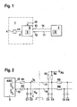
- FIG. 1 shows a measuring system consisting of a measuring device 1 and an evaluation unit 2, which are connected to each other via a cable 11.
- the measuring device 1 comprises an interface 5 for transmitting digital signals to the evaluation unit 2, the interface 5 having a clock input 3 and a signal input 10.
- the supplied at the clock input 3 clock is generated by a clock 4, such as a quartz or oscillator, and has a Frequency of about 10 MHz, the frequency may have relatively high deviations or fluctuations depending on the quality of the clock.
- the measuring device 1 is essentially based on digital signal processing and outputs a digital measurement signal to the interface 5.
- a processing unit contained in the interface 5 processes the supplied clock and measurement signal and calculates therefrom an output signal whose frequency or period duration is dependent on the measurement signal.
- the output signal is thus a signal derived from the system clock and the measured value with variable period duration. In particular, there is a linear relationship between the period of the system clock and the output signal.
- the payload i. the measured value contained in the period or frequency of the output signal thus shows the same deviations as the clock signal.
- a reference signal is generated, which is derived from the clock signal.
- the reference signal is transmitted via a reference signal output 13 of the interface 5 to the evaluation unit 2 and has a relatively low frequency of about 20 Hz.
- FIG. 2 shows the interconnection of interface 5 and evaluation unit 2 (motor control) in detail.
- the digital interface 5 has a clock input 3 and a signal input 10.
- the interface 5 is designed as an ASIC and also has a signal output 12 for a first measurement signal (air mass) and a signal output 13 for the reference signal and a second measurement signal (temperature).
- the two signal outputs 12, 13 are each terminated with a resistor R1, R2 and a switched to ground capacitance C1, C2.
- the capacitances C1, C2 are used for the derivation of high-frequency interference components, in particular for compliance with EMC regulations.
- the measurement signal for determining the air mass is transmitted via the line 11 and the measurement signal for determining the temperature via the line 14 to the engine control.
- the evaluation of the transmitted signal information is carried out according to standardized standard characteristics, so that the motor control can determine the physical values for air mass and temperature by means of defined arithmetic operations.
- the engine controller further includes a pullup circuit for generating a high level.
- the pull-up circuit comprises resistors R3 and R4, one terminal of which is connected to a transmission line 11, 14, and whose other terminal is connected to a supply voltage U PU .
- the motor control for each line 11, 14 comprises an RC low pass for the protection of a downstream controller (not shown).
- the RC low passes include resistors R5, R6 and capacitances C5, C6.
- the switching edges of the measuring device are limited in the rise and fall time, wherein the rise time is determined primarily by the pullup circuit in the engine control.
- the output stage of the measuring system is protected against the usual environmental influences, such as ESD, EMC radiation, glitches, etc. and should also be able to withstand operating errors such as short circuits.
Description
- Die Erfindung betrifft ein Messsystem gemäß dem Oberbegriff des Patentanspruchs 1, sowie ein Verfahren zur Verbesserung der Messgenauigkeit eines solchen Systems gemäß Patentanspruch 14.
- Aus der
US 4626621 ist bereits eine Messvorrichtung bekannt, die eine digitale Schnittstelle 1 aufweist. Messsysteme mit einem oder mehreren Sensoren sowie einer zugehörigen Auswerteeinheit sind weit verbreitet. Zur Veranschaulichung des prinzipiellen Aufbaus solcher Messsysteme wird nachfolgend ein aus der Kfz-Technik bekannter Luftmassensensor beispielhaft näher erläutert. Die Erfindung soll jedoch nicht auf Luftmassensensoren beschränkt sein. - Um den Durchsatz eines strömenden Mediums, wie beispielsweise Luft, ermitteln zu können, umfassen Motoreinspritzanlagen einen Massendurchflussmesser, der in der Literatur auch als Luftmassensensor bezeichnet wird. Bei solchen bekannten Massenstromsensoren wird das Sensorelement einem Luftstrom im Saugrohr der Brennkraftmaschine ausgesetzt. Das Sensorelement umfasst dabei einen Heizer sowie Messwiderstände, die durch den Luftstrom konvektiv gekühlt werden, wodurch eine Widerstandsänderung auftritt. Der durch das Saugrohr fließende Luftstrom kann aus der Verstimmung einer Messbrücke ermittelt werden. Der Sensor stellt schließlich ein Messsignal bereit, das an eine entfernt angeordnete Auswerteeinheit übertragen wird.
- Zu diesem Zweck umfasst ein Luftmassensensor ferner eine (digitale) Schnittstelle zur Übertragung des Messsignals. Die Auswerteeinheit extrahiert die Nutzinformation aus dem empfangenen Signal und wertet sie aus.
- Ein typisches Beispiel eines solchen Messsystems mit digitaler Schnittstelle ist in
Figur 3 schematisch dargestellt. Das gezeigte Messsystem umfasst eine Messeinrichtung 1 mit einer Schnittstelle 5 zur Übertragung digitaler Signale an eine Auswerteeinheit 2. Die Messeinrichtung 1 und die Auswerteeinheit 2 sind über ein Kabel 11 miteinander verbunden. - Die Schnittstelle 5 basiert im wesentlichen auf digitaler Schaltungstechnik und umfasst einen Takteingang 3, an dem ein Takt mit einer bestimmten Frequenz (z.B. 10 MHz) zugeführt wird, und einen Signaleingang 10, an dem das Messsignal des Sensors anliegt.
- Die Schnittstelle 5 umfasst ferner eine Recheneinheit 6, welche das Messsignal verarbeitet und ein entsprechendes Signal am Signalausgang 7 der Schnittstelle 5 ausgibt.
- Das Ausgangssignal ist i.d.R. ein aus dem Systemtakt und dem Messsignal abgeleitetes Signal. Somit besteht zwischen Takt - und Ausgangssignal meist ein linearer Zusammenhang.
- Die Übertragung der Nutzinformation (des Messwertes) kann grundsätzlich mittels aller bekannten Übertragungsverfahren, wie z.B. Modulationsverfahren, durchgeführt werden. Die Nutzinformation kann aber auch im Tastverhältnis oder in der Frequenz bzw. Periodendauer des Ausgangssignals abgebildet sein.
- Bei bekannten Systemen ist das Nutzsignal üblicherweise in der Periodendauer des Ausgangssignals enthalten, da eine solche Kodierung einerseits relativ einfach zu realisieren ist und andererseits eine sehr hohe Messgenauigkeit ermöglicht.
- Der am Takteingang 3 anliegende Systemtakt wird von einem Taktgeber 4, wie z.B. einem Oszillator oder Quarz, erzeugt. Solche Oszillatoren bzw. Quarze können hohe Toleranzen bzw. Taktschwankungen aufweisen. Die Abweichung des Systemtakts wirkt sich jedoch direkt proportional auf das Ausgangssignal aus und kann somit die Messgenauigkeit stark beeinträchtigen.
- Solche Messsysteme können insbesondere bei Anwendungen mit großem Messbereich die vorgegebenen Anforderungen an die Messtoleranz nur dann erfüllen, wenn hochgenaue Quarze bzw. Oszillatoren eingesetzt werden. Präzise Quarze sind jedoch entsprechend teuer und können aus Kostengründen nicht ohne weiteres integriert werden.
- Es ist daher die Aufgabe der vorliegenden Erfindung, ein Messsystem zu schaffen, das mit kostengünstigen Quarzen bzw. Oszillatoren auskommt und dennoch geringe Messtoleranzen aufweist.
- Gelöst wird diese Aufgabe gemäß den Merkmalen des Patentanspruchs 1 sowie durch ein Verfahren gemäß Patentanspruch 14. Weitere Ausgestaltungen der Erfindung sind Gegenstand von Unteransprüchen.
- Der grundlegende Gedanke der Erfindung besteht darin, ein zusätzliches Referenzsignal aus dem Systemtakt abzuleiten und an die Auswerteeinheit zu übertragen. Dieses Referenzsignal wird dazu genutzt, einen Korrekturfaktor zu berechnen, der die Abweichung der Taktfrequenz von einer Soll-Taktfrequenz, und damit auch die Abweichung der Frequenz bzw. Periodendauer des Mess-Ausgangssignals vom nicht abweichenden Ausgangssignal wiedergibt. Dieser Korrekturfaktor wird bei der Auswertung des Ausgangssignals berücksichtigt, d.h., die Frequenzabweichung des Referenzsignals wird genutzt, um das Ausgangssignal zu korrigieren.
- Die Frequenz des Referenzsignals bzw. dessen Periodendauer ist vorzugsweise um einen Faktor N kleiner als diejenige des Taktsignals und liegt insbesondere in einem Bereich von unter 100 Hz, insbesondere unter 50 Hz und vorzugsweise bei etwa 20 Hz. Das Taktsignal hat demgegenüber eine Frequenz von z.B. 10MHz.
- Gemäß einer bevorzugten Ausgestaltung der Erfindung hat die Schnittstelle des Sensors einen frequenzvariablen Signalausgang, d.h., das Ausgangssignal weist in Abhängigkeit vom Messsignal eine unterschiedliche Periodendauer auf.
- Gemäß einer bevorzugten Ausführungsform der Erfindung umfasst die Auswerteeinheit eine Recheneinheit, um insbesondere den korrekturfaktor zur Korrektur des Ausgangssignals aus dem Referenzsignal zu berechnen.
- Das erfindungsgemäße Messsystem kann beispielsweise in der Fahrzeugtechnik zur Optimierung der Kraftstoffeinspritzung verwendet werden. In diesem Fall würde das Messsystem einen Luftmassenmesser und eine zugehörige Auswerteeinheit umfassen.
- Zur Kompensation des Temperaturgangs der Sensorkennlinie umfasst der Luftmassenmesser vorzugsweise einen Temperatursensor, dessen Messwerte ebenfalls zur Auswerteeinheit übertragen werden.
- Die Temperaturwerte werden vorzugsweise zusammen mit dem Referenzsignal übertragen. Gemäß einer bevorzugten Ausgestaltung der Erfindung sind die Temperaturwerte im Tastverhältnis des Referenzsignals enthalten. Die Temperaturwerte können aber auch über andere Übertragungswege oder mittels anderer Übertragungsverfahren übertragen werden.
- Gemäß einer bevorzugten Ausführungsform der Erfindung ist die Periodendauer des Ausgangssignales in Schritten von <=500 ns und vorzugsweise <=200 ns quantisiert. Die Frequenz des Ausgangssignals liegt vorzugsweise zwischen etwa 1,5 und 12 kHz.
- Die Übertragung von Messwerten erfolgt insbesondere nach Standardkennlinien, d.h. die Messwerte sind vorzugsweise normiert und somit unabhängig von der jeweiligen Dimensionierung des Messplatzes, wie beispielsweise dem Saugrohr eines Motors.
- Die Kennlinie der Messeinrichtung ist z.B. ein Polynom n-ter Ordnung und insbesondere ein Polynom dritter Ordnung.
- Die Erfindung wird nachstehend anhand der beigefügten Figuren beispielhaft näher erläutert. Es zeigen:
-
Figur 1 eine Prinzipdarstellung eines Messsystems mit digitaler Schnittstelle gemäß einer Ausführungsform der Erfindung; -
Figur 2 die Verschaltung von Sensorschnittstelle und Auswerteeinheit; und -
Figur 3 eine Prinzipdarstellung eines bekannten Messsystems mit digitaler Schnittstelle. -
Figur 1 zeigt ein Messsystem, bestehend aus einer Messeinrichtung 1 und einer Auswerteeinheit 2, die über ein Kabel 11 miteinander verbunden sind. - Die Messeinrichtung 1 umfasst eine Schnittstelle 5 zur Übertragung digitaler Signale an die Auswerteeinheit 2, wobei die Schnittstelle 5 einen Takteingang 3 und einen Signaleingang 10 aufweist.
- Der am Takteingang 3 zugeführte Takt wird von einem Taktgeber 4, wie z.B. einem Quarz oder Oszillator, erzeugt und hat eine Frequenz von etwa 10 MHz, wobei die Frequenz je nach Güte des Taktgebers relativ hohe Abweichungen bzw. Schwankungen aufweisen kann.
- Die Messeinrichtung 1 basiert im wesentlichen auf digitaler Signalverarbeitung und gibt ein digitales Messsignal an die Schnittstelle 5 aus. Eine in der Schnittstelle 5 enthaltene Recheneinheit verarbeitet das zugeführte Takt- und Messsignal und berechnet daraus ein Ausgangssignal, dessen Frequenz bzw. Periodendauer vom Messsignal abhängig ist. Das Ausgangssignal ist also ein aus dem Systemtakt und dem Messwert abgeleitetes Signal mit variabler Periodendauer. Zwischen der Periodendauer des Systemtakts und des Ausgangssignals besteht insbesondere ein linearer Zusammenhang.
- Die Nutzinformation, d.h. der Messwert, der in der Periodendauer bzw. Frequenz des Ausgangssignals enthalten ist, zeigt somit die gleichen Abweichungen wie das Taktsignal.
- Zur Kompensation dieser Abweichungen wird ein Referenzsignal erzeugt, das aus dem Taktsignal abgeleitet ist. Das Referenzsignal wird über einen Referenzsignalausgang 13 der Schnittstelle 5 an die Auswerteeinheit 2 übertragen und hat eine relativ niedrige Frequenz von etwa 20 Hz.
- Die Abweichung der Periodendauer des Referenzsignals wird bei der Auswertung des Messsignals berücksichtigt. Hierzu berechnet eine in der Auswerteeinheit 2 enthaltene Recheneinheit 9 einen Korrekturfaktor k, mit

- Die Recheneinheit 9 ermittelt schließlich unter Berücksichtigung des Korrekturfaktors k den eigentlichen Messwert, wie z.B. die einen Kanal durchströmende Luftmasse. Die in diesem Beispiel verwendete Kennlinie ist ein Polynom dritter Ordnung, das als Ergebnis den prozentualen Anteil einer maximalen Luftmasse mmax liefert:

- a ein absoluter Anteil der Standardkennlinie,
- b ein linearer Anteil der Standardkennlinie,
- T0 ein Kennlinienoffset,
- Tnorm der Kennlinienbereich und
- TK die korrigierte Periodendauer ist.
- Dabei ergibt sich die korrigierte Periodendauer TK aus:

-
Figur 2 zeigt die Verschaltung von Schnittstelle 5 und Auswerteeinheit 2 (Motorsteuerung) im Detail. Die digitale Schnittstelle 5 hat einen Takteingang 3 und einen Signaleingang 10. Die Schnittstelle 5 ist als ASIC ausgeführt und hat ferner einen Signalausgang 12 für ein erstes Messsignal (Luftmasse) und einen Signalausgang 13 für das Referenzsignal und ein zweites Messsignal (Temperatur). - Die beiden Signalausgänge 12, 13 sind jeweils mit einem Widerstand R1, R2 und einer gegen Masse geschalteten Kapazität C1, C2 abgeschlossen. Dabei dienen die Kapazitäten C1, C2 zur Ableitung hochfrequenter Störanteile, insbesondere zur Einhaltung von EMV-Vorschriften.
- Das Messsignal zur Bestimmung der Luftmasse wird über die Leitung 11 und das Messsignal zur Bestimmung der Temperatur über die Leitung 14 an die Motorsteuerung übertragen.
- Die Auswertung der übertragenen Signalinformation erfolgt nach normierten Standardkennlinien, so dass die Motorsteuerung durch definierte Rechenoperationen die physikalischen Werte für Luftmasse und Temperatur ermitteln kann.
- Die Motorsteuerung umfasst ferner eine Pullup-Schaltung zur Erzeugung eines High-Pegels. Die Pullup-Schaltung umfasst Widerstände R3 bzw. R4, deren einer Anschluss jeweils mit einer Übertragungsleitung 11, 14 verbunden ist, und deren anderer Anschluss an einer Versorgungsspannung UPU angeschlossen ist.
- Zur Entstörung der Leitungen 11, 14 sind wiederum gegen Masse geschaltete Kapazitäten C3, C4 vorgesehen.
- Weiterhin umfasst die Motorsteuerung für jede Leitung 11, 14 einen RC-Tiefpass zum Schutz eines nachgeschalteten Controllers (nicht gezeigt). Die RC-Tiefpässe umfassen Widerstände R5, R6 und Kapazitäten C5, C6.
- Die Schaltflanken der Messeinrichtung sind in der Anstiegs - und Abfallzeit begrenzt, wobei die Anstiegszeit in erster Linie durch die Pullup-Schaltung in der Motorsteuerung bestimmt wird.
- Die Endstufe der Messeinrichtung.ist gegen die üblichen Umwelteinflüsse, wie ESD, EMV-Einstrahlung, Störimpulse usw. geschützt und sollte auch Fehlbedienungen, wie z.B. Kurzschlüsse, überstehen können.
-
- 1
- Messeinrichtung
- 2
- Auswerteeinheit
- 3
- Takteingang
- 4
- Taktgeber
- 5
- Schnittstelle
- 6
- Recheneinheit
- 7
- Signalausgang
- 8
- Referenzsignalausgang
- 9
- Recheneinheit
- 10
- Signaleingang
- 11
- Kabel
- 12
- Signalausgang
- 13
- Referenzsignalausgang
- 14
- Kabel
- R1-R6
- Widerstände
- C1-C6
- Kapazitäten
Claims (11)
- Messeinrichtung (1) mit einer digitalen Schnittstelle (5), wobei die Schnittstelle (5)- einen Takteingang (3), an dem ein Taktgeber (4) mit einem Taktsignal angeschlossen ist, aufweist,- einen Signaleingang (10) aufweist, an dem ein Messsignal anliegt,- eine Recheneinheit (6) aufweist, die ein aus dem Taktsignal und dem Messsignal abgeleitetes Ausgangssignal erzeugt, wobei das Messsignal in dem Ausgangssignal in einer Frequenz bzw. Periodendauer oder einem Tastverhältnis abgebildet ist und- einen Signalausgang (12) aufweist, an dem das Ausgangssignal zur Übertragung an eine Auswerteeinheit (2) ausgegeben wird, wobei die Schnittstelle (5) einen weiteren Signalausgang (13) aufweist, an dem ein aus dem Taktsignal abgeleitetes Referenzsignal ausgegeben wird, wobei das Referenzsignal eine Abweichung des Taktsignals von einer Soll-Taktfrequenz wiedergibt.
- Messeinrichtung nach Anspruch 1, wobei die Frequenz des Referenzsignals um einen Faktor N kleiner ist als diejenige des Taktsignals.
- Messeinrichtung nach einem der vorhergehenden Ansprüche, wobei die Messeinrichtung (1) einen zweiten Sensor aufweist.
- Messeinrichtung nach Anspruch 3, wobei die Messwerte des zweiten Sensors zusammen mit dem Referenzsignal übertragen werden.
- Messeinrichtung nach Anspruch 4, wobei der Messwert des zweiten Sensors im Tastverhältnis des Referenzsignals enthalten ist.
- Messeinrichtung nach einem der vorhergehenden Ansprüche, wobei die Messeinrichtung (1) ein Luftmassenmesser ist.
- Messeinrichtung nach einem der vorhergehenden Ansprüche, wobei die Periode des Ausgangssignals in Schrittweiten von <=500 ns, insbesondere <=200 ns quantisiert ist.
- Messeinrichtung nach einem der vorhergehenden Ansprüche, wobei die Frequenz des Referenzsignals <100 Hz, insbesondere <50 Hz und vorzugsweise ungefähr 20 Hz beträgt.
- Messeinrichtung nach einem der vorhergehenden Ansprüche, wobei die Frequenz des Ausgangssignals zwischen 1,5 und 12 kHz liegt.
- Auswerteeinheit (2) zur Zusammenarbeit mit einem Messeinrichtung (1) nach einem der vorhergehenden Ansprüche, wobei eine Recheneinheit (9) vorgesehen ist die aus dem Ausgangssignal der Messeinrichtung (1) den Messwert ermittelt und dabei einen Korrekturfaktor berücksichtigt der aus dem Referenzsignal ermittelt ist.
- Verfahren zur Korrektur des Ausgangssignals einer Messeinrichtung mit einer digitalen Schnittstelle, der ein Mess- sowie ein Taktsignal zugeführt wird, gekennzeichnet durch folgende Schritte:- Erzeugen eines aus dem Taktsignal und dem Messsignal abgeleiteten Ausgangssignals und Übertragen des Ausgangssignals an eine Auswerteeinheit (2) wobei das Messsignal in dem Ausgangssignal in einer Frequenz bzw. Periodendauer oder einem Tastverhältnis abgebildet ist;- Erzeugen eines aus dem Taktsignal abgeleiteten Referenzsignals und Übertragen des Referenzsignals an die Auswerteeinheit (2) wobei das Referenzsignal eine Abweichung des Taktsignals von einer Soll-Taktfrequenz wiedergibt;- Auswerten des Ausgangssignals, wobei Abweichungen des Ausgangssignals mit Hilfe des Referenzsignals korrigiert werden.
Applications Claiming Priority (3)
| Application Number | Priority Date | Filing Date | Title |
|---|---|---|---|
| DE10140617A DE10140617A1 (de) | 2001-08-18 | 2001-08-18 | Messsystem mit ratiometrischem Frequenzausgang |
| DE10140617 | 2001-08-18 | ||
| PCT/DE2002/002628 WO2003019116A1 (de) | 2001-08-18 | 2002-08-13 | Messsystem mit ratiometrischem frequenzausgang |
Publications (2)
| Publication Number | Publication Date |
|---|---|
| EP1421336A1 EP1421336A1 (de) | 2004-05-26 |
| EP1421336B1 true EP1421336B1 (de) | 2012-10-24 |
Family
ID=7695912
Family Applications (1)
| Application Number | Title | Priority Date | Filing Date |
|---|---|---|---|
| EP02754380A Expired - Lifetime EP1421336B1 (de) | 2001-08-18 | 2002-08-13 | Messsystem mit ratiometrischem frequenzausgang |
Country Status (8)
| Country | Link |
|---|---|
| US (1) | US7012418B2 (de) |
| EP (1) | EP1421336B1 (de) |
| JP (1) | JP4695833B2 (de) |
| KR (1) | KR20040030970A (de) |
| CN (1) | CN1253695C (de) |
| DE (1) | DE10140617A1 (de) |
| RU (1) | RU2291451C2 (de) |
| WO (1) | WO2003019116A1 (de) |
Families Citing this family (9)
| Publication number | Priority date | Publication date | Assignee | Title |
|---|---|---|---|---|
| DE102006042807A1 (de) * | 2006-09-08 | 2008-03-27 | Endress + Hauser Conducta Gesellschaft für Mess- und Regeltechnik mbH + Co. KG | Messanordnung mit großer Messbereichsdynamik |
| DE102009002289A1 (de) * | 2009-04-08 | 2010-10-14 | Endress + Hauser Flowtec Ag | Verfahren zum Ermitteln einer Periodendauer eines Meßsignals |
| IT1394791B1 (it) * | 2009-05-20 | 2012-07-13 | Metallux Sa | Sensore di pressione |
| CN101944054B (zh) * | 2009-07-06 | 2013-11-06 | 鸿富锦精密工业(深圳)有限公司 | 频率范围测试系统及方法 |
| TWI464417B (zh) * | 2009-07-10 | 2014-12-11 | Hon Hai Prec Ind Co Ltd | 頻率範圍測試系統及方法 |
| DE102011003306B3 (de) * | 2011-01-28 | 2012-04-05 | Siemens Aktiengesellschaft | Schaltungsanordnung zur Erfassung und Digitalisierung eines analogen Eingangssignals sowie Feldgerät zur Prozessinstrumentierung |
| WO2014043621A1 (en) | 2012-09-14 | 2014-03-20 | Abc Global, Llc | Cool comfort suit |
| US9835575B2 (en) * | 2014-10-16 | 2017-12-05 | Ams International Ag | Ratiometric device |
| US11734202B2 (en) * | 2020-09-17 | 2023-08-22 | Baker Hughes Oilfield Operations Llc | Sensor interface |
Family Cites Families (8)
| Publication number | Priority date | Publication date | Assignee | Title |
|---|---|---|---|---|
| NL8001444A (nl) | 1980-03-11 | 1981-10-01 | Anderson & Vreeland Bv | Inrichting voor het meten en regelen van de viscositeit van een vloeistof. |
| US4626621A (en) | 1983-08-10 | 1986-12-02 | Diesel Kiki Co., Ltd. | Circuit for generating a position in digital form |
| JP2534045B2 (ja) * | 1986-12-22 | 1996-09-11 | 株式会社ゼクセル | 回転角度−時間変換装置 |
| US5231884A (en) * | 1991-07-11 | 1993-08-03 | Micro Motion, Inc. | Technique for substantially eliminating temperature induced measurement errors from a coriolis meter |
| KR100413402B1 (ko) * | 1995-04-10 | 2004-04-28 | 지멘스 악티엔게젤샤프트 | 모델을이용하여내연기관실린더내측으로의공기질량을측정하는방법 |
| AUPO072096A0 (en) * | 1996-06-28 | 1996-07-25 | Curtin University Of Technology | Precise digital frequency detection |
| DE69937620T2 (de) * | 1998-07-09 | 2008-10-23 | Honda Giken Kogyo K.K. | Verfahren zur Entnahme einer Abgasprobe unter Verwendung eines Durchflussmengenmessers mit veränderbarem Venturiabschnitt |
| JP2001127623A (ja) * | 1999-10-27 | 2001-05-11 | Matsushita Electric Ind Co Ltd | ジッタ検出回路 |
-
2001
- 2001-08-18 DE DE10140617A patent/DE10140617A1/de not_active Withdrawn
-
2002
- 2002-08-13 JP JP2003523936A patent/JP4695833B2/ja not_active Expired - Fee Related
- 2002-08-13 EP EP02754380A patent/EP1421336B1/de not_active Expired - Lifetime
- 2002-08-13 CN CNB028161572A patent/CN1253695C/zh not_active Expired - Fee Related
- 2002-08-13 KR KR10-2004-7002317A patent/KR20040030970A/ko not_active Application Discontinuation
- 2002-08-13 RU RU2004108050/28A patent/RU2291451C2/ru not_active IP Right Cessation
- 2002-08-13 US US10/486,641 patent/US7012418B2/en not_active Expired - Fee Related
- 2002-08-13 WO PCT/DE2002/002628 patent/WO2003019116A1/de active Application Filing
Also Published As
| Publication number | Publication date |
|---|---|
| CN1253695C (zh) | 2006-04-26 |
| JP4695833B2 (ja) | 2011-06-08 |
| RU2291451C2 (ru) | 2007-01-10 |
| JP2005500634A (ja) | 2005-01-06 |
| RU2004108050A (ru) | 2005-06-10 |
| EP1421336A1 (de) | 2004-05-26 |
| US7012418B2 (en) | 2006-03-14 |
| WO2003019116A1 (de) | 2003-03-06 |
| US20040183516A1 (en) | 2004-09-23 |
| KR20040030970A (ko) | 2004-04-09 |
| CN1543563A (zh) | 2004-11-03 |
| DE10140617A1 (de) | 2003-03-06 |
Similar Documents
| Publication | Publication Date | Title |
|---|---|---|
| DE4035731C2 (de) | Kraftstoffkonzentrations-Überwachungseinheit | |
| EP2623940B1 (de) | Prüfung einer Messgerätanordnung, entsprechende Messgerätanordnung und Prüfanordnung | |
| DE10392816B4 (de) | Vorrichtung und Verfahren zur Kompensation des Ausgangssignals eines Sensors | |
| EP1421336B1 (de) | Messsystem mit ratiometrischem frequenzausgang | |
| DE4334090C2 (de) | Verfahren und System zur Messung eines Luftstromdurchsatzes | |
| DE4015415A1 (de) | Vorrichtung zur erfassung eines veraenderlichen betriebsparameters | |
| WO2014206633A1 (de) | Verfahren und vorrichtung zur bestimmung einer temperatur eines an einem messfühler vorbeiströmenden gases | |
| DE102012218274A1 (de) | Paralleles Auslesen eines analogen Sensors durch zwei Steuereinheiten | |
| EP0273103B1 (de) | Schaltungsanordnung für einen Sensor | |
| EP1134589A2 (de) | Verfahren zur Detektion einer fehlerhaften Masseverbindung in einer elektrischen Einrichtung insbesondere eines Kraftfahrzeugs | |
| DE2518890B2 (de) | Linearisierungsvorrichtung | |
| DE10054745B4 (de) | Verfahren zur sicheren Übertragung von Sensorsignalen und Vorrichtung zum Ausführen des Verfahrens | |
| DE102013214825B4 (de) | Verfahren zum Anpassen der Übertragungseigenschaften eines Signals | |
| DE102014220522B4 (de) | Bestimmung eines korrigierten Drucksignals | |
| EP1421335B1 (de) | Verfahren zur korrektur einer oszillatorfrequenz | |
| DE10123627A1 (de) | Sensorvorrichtung zum Erfassen einer mechanischen Deformation | |
| DE102009027243A1 (de) | Vorrichtung zur Aufbereitung eines Sensorsignals eines Fahrzeugsensors, Sensorvorrichtung und Verfahren zum Bestimmen einer Temperatur eines Getriebeöls eines Fahrzeuggetriebes | |
| DE3437445A1 (de) | Verfahren und einrichtung zur kompensation der temperaturabhaengigkeit einer elektrochemischen messzelle | |
| DE102014102734B4 (de) | Sensorsysteme und Verfahren mit emulierter Leitungsanpassung | |
| DE102018217814B4 (de) | Verfahren zur Offsetkalibrierung eines Drehratensensorsignals eines Drehratensensors, System, Computerprogramm | |
| DE3905665C2 (de) | Anordnung zur Messung des Massenstroms | |
| DE102008054994B4 (de) | Verfahren und Vorrichtung zur Spannungsversorgung von einem analogen Sensor | |
| DE19722549A1 (de) | Elektrische Meßeinrichtung bzw. elektrisches Meßverfahren zur Erzeugung eines elektrischen Signals | |
| EP1073880A2 (de) | Einrichtung zum ratiometrischen messen von sensorsignalen | |
| WO2003027684A2 (de) | Verfahren und vorrichtung zum überwachen einer sensoreinheit |
Legal Events
| Date | Code | Title | Description |
|---|---|---|---|
| PUAI | Public reference made under article 153(3) epc to a published international application that has entered the european phase |
Free format text: ORIGINAL CODE: 0009012 |
|
| 17P | Request for examination filed |
Effective date: 20040318 |
|
| AK | Designated contracting states |
Kind code of ref document: A1 Designated state(s): AT BE BG CH CY CZ DE DK EE ES FI FR GB GR IE IT LI LU MC NL PT SE SK TR |
|
| RIN1 | Information on inventor provided before grant (corrected) |
Inventor name: REISCHL, ROLF Inventor name: LOISTL, HANS Inventor name: STROHRMANN, MANFRED Inventor name: NEUSCHELER, MARCO Inventor name: BRUECKNER, JOERG Inventor name: HAAG, AXEL-WERNER |
|
| 17Q | First examination report despatched |
Effective date: 20090209 |
|
| GRAP | Despatch of communication of intention to grant a patent |
Free format text: ORIGINAL CODE: EPIDOSNIGR1 |
|
| GRAS | Grant fee paid |
Free format text: ORIGINAL CODE: EPIDOSNIGR3 |
|
| GRAA | (expected) grant |
Free format text: ORIGINAL CODE: 0009210 |
|
| AK | Designated contracting states |
Kind code of ref document: B1 Designated state(s): AT BE BG CH CY CZ DE DK EE ES FI FR GB GR IE IT LI LU MC NL PT SE SK TR |
|
| REG | Reference to a national code |
Ref country code: GB Ref legal event code: FG4D Free format text: NOT ENGLISH |
|
| REG | Reference to a national code |
Ref country code: CH Ref legal event code: EP |
|
| REG | Reference to a national code |
Ref country code: AT Ref legal event code: REF Ref document number: 581172 Country of ref document: AT Kind code of ref document: T Effective date: 20121115 |
|
| REG | Reference to a national code |
Ref country code: IE Ref legal event code: FG4D Free format text: LANGUAGE OF EP DOCUMENT: GERMAN |
|
| REG | Reference to a national code |
Ref country code: DE Ref legal event code: R096 Ref document number: 50215637 Country of ref document: DE Effective date: 20121220 |
|
| REG | Reference to a national code |
Ref country code: NL Ref legal event code: VDEP Effective date: 20121024 |
|
| PG25 | Lapsed in a contracting state [announced via postgrant information from national office to epo] |
Ref country code: NL Free format text: LAPSE BECAUSE OF FAILURE TO SUBMIT A TRANSLATION OF THE DESCRIPTION OR TO PAY THE FEE WITHIN THE PRESCRIBED TIME-LIMIT Effective date: 20121024 Ref country code: SE Free format text: LAPSE BECAUSE OF FAILURE TO SUBMIT A TRANSLATION OF THE DESCRIPTION OR TO PAY THE FEE WITHIN THE PRESCRIBED TIME-LIMIT Effective date: 20121024 Ref country code: FI Free format text: LAPSE BECAUSE OF FAILURE TO SUBMIT A TRANSLATION OF THE DESCRIPTION OR TO PAY THE FEE WITHIN THE PRESCRIBED TIME-LIMIT Effective date: 20121024 |
|
| PG25 | Lapsed in a contracting state [announced via postgrant information from national office to epo] |
Ref country code: PT Free format text: LAPSE BECAUSE OF FAILURE TO SUBMIT A TRANSLATION OF THE DESCRIPTION OR TO PAY THE FEE WITHIN THE PRESCRIBED TIME-LIMIT Effective date: 20130225 Ref country code: GR Free format text: LAPSE BECAUSE OF FAILURE TO SUBMIT A TRANSLATION OF THE DESCRIPTION OR TO PAY THE FEE WITHIN THE PRESCRIBED TIME-LIMIT Effective date: 20130125 Ref country code: CY Free format text: LAPSE BECAUSE OF FAILURE TO SUBMIT A TRANSLATION OF THE DESCRIPTION OR TO PAY THE FEE WITHIN THE PRESCRIBED TIME-LIMIT Effective date: 20121024 |
|
| PG25 | Lapsed in a contracting state [announced via postgrant information from national office to epo] |
Ref country code: BG Free format text: LAPSE BECAUSE OF FAILURE TO SUBMIT A TRANSLATION OF THE DESCRIPTION OR TO PAY THE FEE WITHIN THE PRESCRIBED TIME-LIMIT Effective date: 20130124 Ref country code: CZ Free format text: LAPSE BECAUSE OF FAILURE TO SUBMIT A TRANSLATION OF THE DESCRIPTION OR TO PAY THE FEE WITHIN THE PRESCRIBED TIME-LIMIT Effective date: 20121024 Ref country code: DK Free format text: LAPSE BECAUSE OF FAILURE TO SUBMIT A TRANSLATION OF THE DESCRIPTION OR TO PAY THE FEE WITHIN THE PRESCRIBED TIME-LIMIT Effective date: 20121024 Ref country code: EE Free format text: LAPSE BECAUSE OF FAILURE TO SUBMIT A TRANSLATION OF THE DESCRIPTION OR TO PAY THE FEE WITHIN THE PRESCRIBED TIME-LIMIT Effective date: 20121024 Ref country code: SK Free format text: LAPSE BECAUSE OF FAILURE TO SUBMIT A TRANSLATION OF THE DESCRIPTION OR TO PAY THE FEE WITHIN THE PRESCRIBED TIME-LIMIT Effective date: 20121024 |
|
| PLBE | No opposition filed within time limit |
Free format text: ORIGINAL CODE: 0009261 |
|
| STAA | Information on the status of an ep patent application or granted ep patent |
Free format text: STATUS: NO OPPOSITION FILED WITHIN TIME LIMIT |
|
| 26N | No opposition filed |
Effective date: 20130725 |
|
| PG25 | Lapsed in a contracting state [announced via postgrant information from national office to epo] |
Ref country code: ES Free format text: LAPSE BECAUSE OF FAILURE TO SUBMIT A TRANSLATION OF THE DESCRIPTION OR TO PAY THE FEE WITHIN THE PRESCRIBED TIME-LIMIT Effective date: 20130204 |
|
| REG | Reference to a national code |
Ref country code: DE Ref legal event code: R097 Ref document number: 50215637 Country of ref document: DE Effective date: 20130725 |
|
| PGFP | Annual fee paid to national office [announced via postgrant information from national office to epo] |
Ref country code: FR Payment date: 20130820 Year of fee payment: 12 |
|
| PGFP | Annual fee paid to national office [announced via postgrant information from national office to epo] |
Ref country code: IT Payment date: 20130826 Year of fee payment: 12 |
|
| BERE | Be: lapsed |
Owner name: ROBERT BOSCH G.M.B.H. Effective date: 20130831 |
|
| REG | Reference to a national code |
Ref country code: CH Ref legal event code: PL |
|
| GBPC | Gb: european patent ceased through non-payment of renewal fee |
Effective date: 20130813 |
|
| PG25 | Lapsed in a contracting state [announced via postgrant information from national office to epo] |
Ref country code: CH Free format text: LAPSE BECAUSE OF NON-PAYMENT OF DUE FEES Effective date: 20130831 Ref country code: LI Free format text: LAPSE BECAUSE OF NON-PAYMENT OF DUE FEES Effective date: 20130831 Ref country code: MC Free format text: LAPSE BECAUSE OF FAILURE TO SUBMIT A TRANSLATION OF THE DESCRIPTION OR TO PAY THE FEE WITHIN THE PRESCRIBED TIME-LIMIT Effective date: 20121024 |
|
| REG | Reference to a national code |
Ref country code: IE Ref legal event code: MM4A |
|
| PG25 | Lapsed in a contracting state [announced via postgrant information from national office to epo] |
Ref country code: BE Free format text: LAPSE BECAUSE OF NON-PAYMENT OF DUE FEES Effective date: 20130831 |
|
| PG25 | Lapsed in a contracting state [announced via postgrant information from national office to epo] |
Ref country code: GB Free format text: LAPSE BECAUSE OF NON-PAYMENT OF DUE FEES Effective date: 20130813 Ref country code: IE Free format text: LAPSE BECAUSE OF NON-PAYMENT OF DUE FEES Effective date: 20130813 |
|
| REG | Reference to a national code |
Ref country code: AT Ref legal event code: MM01 Ref document number: 581172 Country of ref document: AT Kind code of ref document: T Effective date: 20130813 |
|
| PG25 | Lapsed in a contracting state [announced via postgrant information from national office to epo] |
Ref country code: AT Free format text: LAPSE BECAUSE OF NON-PAYMENT OF DUE FEES Effective date: 20130813 |
|
| PG25 | Lapsed in a contracting state [announced via postgrant information from national office to epo] |
Ref country code: IT Free format text: LAPSE BECAUSE OF NON-PAYMENT OF DUE FEES Effective date: 20140813 |
|
| REG | Reference to a national code |
Ref country code: FR Ref legal event code: ST Effective date: 20150430 |
|
| PG25 | Lapsed in a contracting state [announced via postgrant information from national office to epo] |
Ref country code: TR Free format text: LAPSE BECAUSE OF FAILURE TO SUBMIT A TRANSLATION OF THE DESCRIPTION OR TO PAY THE FEE WITHIN THE PRESCRIBED TIME-LIMIT Effective date: 20121024 |
|
| PG25 | Lapsed in a contracting state [announced via postgrant information from national office to epo] |
Ref country code: LU Free format text: LAPSE BECAUSE OF NON-PAYMENT OF DUE FEES Effective date: 20130813 |
|
| PG25 | Lapsed in a contracting state [announced via postgrant information from national office to epo] |
Ref country code: FR Free format text: LAPSE BECAUSE OF NON-PAYMENT OF DUE FEES Effective date: 20140901 |
|
| PGFP | Annual fee paid to national office [announced via postgrant information from national office to epo] |
Ref country code: DE Payment date: 20181024 Year of fee payment: 17 |
|
| REG | Reference to a national code |
Ref country code: DE Ref legal event code: R119 Ref document number: 50215637 Country of ref document: DE |
|
| PG25 | Lapsed in a contracting state [announced via postgrant information from national office to epo] |
Ref country code: DE Free format text: LAPSE BECAUSE OF NON-PAYMENT OF DUE FEES Effective date: 20200303 |