EP1419951A2 - Procédé et dispositif pour système d'amélioration de stabilité de véhicule - Google Patents
Procédé et dispositif pour système d'amélioration de stabilité de véhicule Download PDFInfo
- Publication number
- EP1419951A2 EP1419951A2 EP03023541A EP03023541A EP1419951A2 EP 1419951 A2 EP1419951 A2 EP 1419951A2 EP 03023541 A EP03023541 A EP 03023541A EP 03023541 A EP03023541 A EP 03023541A EP 1419951 A2 EP1419951 A2 EP 1419951A2
- Authority
- EP
- European Patent Office
- Prior art keywords
- vehicle
- state
- yaw rate
- rate error
- register
- Prior art date
- Legal status (The legal status is an assumption and is not a legal conclusion. Google has not performed a legal analysis and makes no representation as to the accuracy of the status listed.)
- Withdrawn
Links
Images


Classifications
-
- B—PERFORMING OPERATIONS; TRANSPORTING
- B60—VEHICLES IN GENERAL
- B60T—VEHICLE BRAKE CONTROL SYSTEMS OR PARTS THEREOF; BRAKE CONTROL SYSTEMS OR PARTS THEREOF, IN GENERAL; ARRANGEMENT OF BRAKING ELEMENTS ON VEHICLES IN GENERAL; PORTABLE DEVICES FOR PREVENTING UNWANTED MOVEMENT OF VEHICLES; VEHICLE MODIFICATIONS TO FACILITATE COOLING OF BRAKES
- B60T8/00—Arrangements for adjusting wheel-braking force to meet varying vehicular or ground-surface conditions, e.g. limiting or varying distribution of braking force
- B60T8/17—Using electrical or electronic regulation means to control braking
- B60T8/1755—Brake regulation specially adapted to control the stability of the vehicle, e.g. taking into account yaw rate or transverse acceleration in a curve
- B60T8/17555—Brake regulation specially adapted to control the stability of the vehicle, e.g. taking into account yaw rate or transverse acceleration in a curve specially adapted for enhancing driver or passenger comfort, e.g. soft intervention or pre-actuation strategies
-
- B—PERFORMING OPERATIONS; TRANSPORTING
- B60—VEHICLES IN GENERAL
- B60T—VEHICLE BRAKE CONTROL SYSTEMS OR PARTS THEREOF; BRAKE CONTROL SYSTEMS OR PARTS THEREOF, IN GENERAL; ARRANGEMENT OF BRAKING ELEMENTS ON VEHICLES IN GENERAL; PORTABLE DEVICES FOR PREVENTING UNWANTED MOVEMENT OF VEHICLES; VEHICLE MODIFICATIONS TO FACILITATE COOLING OF BRAKES
- B60T2260/00—Interaction of vehicle brake system with other systems
- B60T2260/02—Active Steering, Steer-by-Wire
Definitions
- This invention relates generally to a vehicle stability enhancement (VSE) system and a method of operation thereof, and more particularly to an integrated set of vehicle chassis subsystems responsive to a controller that is part of the VSE system.
- VSE vehicle stability enhancement
- a vehicle stability enhancement system for a vehicle having at least one vehicle subsystem, which comprises; at least one sensor for sensing at least one vehicle parameter, at least one vehicle control system for adjusting the at least one vehicle subsystem, a driving mode switch for selecting at least one driving mode, at least one memory comprising at least one set of gain factors, and a controller responsive to the at least one sensor, the driving mode switch, and the at least one set of gain factors for controlling the at least one vehicle control system.
- a method for actively controlling a vehicle stability enhancement system comprises; sensing at least one vehicle parameter, calculating a yaw rate error index (OSUS) in response to the at least one vehicle parameter, calculating the state of at least one control flag in response to the at least one vehicle parameter, determining the state of a driving mode in response to a driving mode request, determining the state of the at least one control flag in response to the state of the driving mode, and determining at least one control gain factor in response to the state of the at least one control flag and the yaw rate error index.
- OSUS yaw rate error index
- Fig. 1 depicts a generalized schematic of a vehicle operative for implementing the present invention
- FIG. 2 depicts a generalized flowchart for implementing the present invention
- Fig. 3 depicts a method for implementing the present invention
- Fig. 4 depicts a flowchart for calculating a yaw rate error index in accordance with the present invention
- Fig. 5 depicts a flowchart for calculating a first control flag in accordance with the present invention
- Fig. 6 depicts a flowchart for calculating a second control flag in accordance with the present invention.
- Fig. 7 depicts a flowchart for determining at least one gain factor in accordance with the present invention.
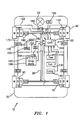
- FIG. 1 depicts a generalized schematic of a vehicle 10 having a chassis 20, a body 30 arranged on chassis 20, a set of wheels (“W”) 40 rotationally coupled to chassis 20, a steering mechanism 50 arranged for steering wheels 40, a braking mechanism (“B”) 60 arranged for decelerating wheels 40 upon command, a suspension mechanism (“S”) 70 disposed between wheels 40 and chassis 20 for damping vibration at wheels 40, and an integrated chassis control system (ICCS) 100.
- W set of wheels
- B braking mechanism
- S suspension mechanism
- ICCS integrated chassis control system
- the ICCS 100 includes: a yaw rate sensor (“Yaw”) 110 for sensing the actual vehicle yaw rate in degrees-per-second; wheel velocity sensors (“VS") 120; a lateral acceleration sensor (“Lat”) 130, such as for example an accelerometer, for sensing the absolute value of the vehicle's lateral acceleration in g-force; a longitudinal acceleration sensor 140 (“Long”) (e.g., accelerometer) for sensing the absolute value of the vehicle's longitudinal acceleration in g-force; a steering angle sensor (“SS”) 150 for sensing the angle of steer for the steering wheels; and a brake pressure sensor (“BS”) 155 for sensing the brake fluid pressure.
- the sensed parameters are herein referred to as vehicle parameters.
- the ICCS 100 also includes the following vehicle control systems: a steering mechanism control system (“WCS”) 160, such as, for example, electronically controlled actuators and dampers, for adjusting the stiffness and damping characteristics of, and the degree of steering assist associated with, the steering mechanism 50; a braking mechanism control system (“BCS”) 170 (e.g., electronically controlled actuators and dampers) for adjusting the stiffness and damping characteristics of, and the degree of pressure-apply rate associated with, the braking mechanism 60; and a suspension mechanism control system (“SCS”) 180 (e.g., electronically controlled actuators and dampers) for adjusting the stiffness and damping characteristics of the suspension mechanism 70.
- WCS steering mechanism control system
- BCS braking mechanism control system
- SCS suspension mechanism control system
- the ICCS 100 further includes: a driving mode switch ("Drvg Mode") 190 for enabling a driver to selectively choose between multiple driving modes, such as, for example, "Normal” and "Sporty” modes, where the "Normal” mode may be for highway cruising and the "Sporty” mode may be for high performance handling; and a central controller 200 arranged in operable communication with sensors 110, 120, 130, 140, 150, 155, and mechanism control systems 160, 170, 180.
- Control lines 162, 172, 182 are depicted, for simplicity, as single lines, but represent both signal communication lines and operational links for communicating with and actuating the mechanism control systems 160, 170, 180, respectively.
- Driving mode switch 190 may include a pushbutton type switch 192, or any other type of switch suitable for producing a driving mode request signal, and a display 194 for providing feedback to the driver regarding the driving mode setting.
- BCS 170 is in operable communication with controller 200 via brake master cylinder ("Mstr Cyl") 210.
- "Mstr Cyl” 210 is also in operable communication with brake pedal (“Brk”) 220.
- Braking mechanism 60 may be operated by the driver via brake pedal 220 and master cylinder 210, or by controller 200 via the ICCS 100, master cylinder 210, and brake mechanism control system 170.
- Brake pressure sensor 155 senses the brake fluid pressure in brake master cylinder 210.
- Controller 200 includes a memory 230 for storing sensor information, register information and settings, discussed below, and look-up tables of gain factors, also discussed below.
- the disclosed embodiment refers to only two driving modes, the invention described herein is applicable to any number of driving modes. It will further be appreciated that while the disclosed embodiment refers to a vehicle, such as an automobile, having four wheels, the invention described herein is applicable to any vehicle with any number of wheels. Such alternative vehicles to the disclosed embodiment may be, for example and without limitation, a three-wheel or six-wheel off-road vehicle, designed with normal, sporty, and hill climbing driving modes.
- Yaw rate error threshold (“Ye_th”) may be set to a predetermined value, such as, for example, 8-deg/sec, or it may be calculated as described in the commonly assigned U.S. Patent No. 5,720,533, entitled “Brake Control System", filed October 15, 1996 (the '533 patent), which is herein incorporated by reference in its entirety.
- Controller 200 is a microprocessor based control system adapted for actively controlling an integrated set of chassis subsytems, for example, steering mechanism 50, braking mechanism 60 and suspension mechanism 70, in accordance with control logic that includes the determination of control gain factors "GYe_th” and “GB_r” for controlling the yaw rate error threshold ("Ye_th”) and brake pressure apply rate (“B_r”).
- Controller 200 typically includes a microprocessor, ROM and RAM, and appropriate input and output circuits of a known type for receiving the various input signals and for outputting the various control commands to the various actuators and control systems.
- the control logic implemented by controller 200 is cycled at a control sampling rate of "T", and is best seen by referring to Figures 2-7.
- a generalized flowchart 300 for implementing the present invention begins at power-up 310, followed by initialization 320, which resets all of the system flags, registers and timers.
- the interrupt-loop-execution 330 step cycles through the control logic at the sampling rate "T", which is best seen by referring to Figure 3.
- process 400 depicts the process represented by block 330 in Figure 2, which begins at start 410 and proceeds to step 420 where vehicle parameters, such as, vehicle yaw rate (“Yaw”), vehicle speed (“Vx”), vehicle lateral acceleration (“ay”), vehicle steering angle (“d”), and master cylinder pressure (“MCP”), are sensed by sensors 110, 120, 130, 150, 155, respectively.
- Equations 3-5 provide one exemplary method of setting the VSE flag.
- Another exemplary method of setting the VSE flag involves an algorithm for computing the yaw rate error (Ye) and the rate of yaw rate error (Ye'), computing proportional and derivative terms for Ye and Ye' by multiplying Ye and Ye' by proportional and derivative gains, respectively, comparing the absolute value of the sum of these terms to a threshold, and setting the VSE flag to ON if the absolute value of the sum is greater than a threshold value and the vehicle speed is greater than a velocity threshold.
- the vehicle yaw rate error is typically passed through a low pass filter having a bandwidth, for example, of about 26 Hertz, thereby filtering out undesirable noise.
- the calculation 440 of yaw rate error index "OSUS" is depicted in detail in Figure 4 and is discussed below.
- the calculations 450 of hi mu surface flag “SFlag(t)” and stability limit flag “LFlag(t)” are depicted in detail in Figures 5 and 6 and are discussed below.
- the actual driving mode "Mode” is determined 460 by controller 200 reading the "Mode" register in memory 230 for a setting of "Normal” or "Sporty".
- Determining 470 the state of control flags "SFlag(t)” and “LFlag(t)” proceeds according to the flowchart of Figure 7, which is discussed below.
- Determining 480 the value of control gain factors "GYe_th” and “GB_r” proceeds in accordance with the flowchart of Figure 7, discussed below, which directs the control logic to enter a set of look-up tables, depicted below as Tables 1-4, with a yaw rate error index ("OSUS" index) as input to the tables.
- Process 400 concludes at step 490, at which point control logic returns to process 300 and proceeds according to control sampling rate "T", or until such time as the system is powered down.
- FIG. 4 depicts a flowchart 500 for calculating yaw rate error index "OSUS”
- OSUS vehicle yaw rate error
- the process continues by determining 520 whether the absolute value of the vehicle yaw rate error "
- " is less than or equal to the calibration value "Ye_thr1". If the conditions of block 520 are satisfied, then control logic continues to block 530 where the ratio of yaw rate error to yaw threshold, "delta_Y”, is calculated 530 according to the equation; delta_Y(new) sign(Ye)*delta_Y(old), where (new) and (old) represent the values of delta_Y at two consecutive iterative steps in the process.
- control logic passes to block 540 and follows the process as discussed above. At the conclusion of process 500, a vehicle OSUS index is determined. After blocks 550 and 560, control logic passes back to block 520.
- a flowchart 600 for calculating a hi mu surface flag "SFlag(t)" (a first control flag) is depicted.
- This algorithm detects if the vehicle is generating a large lateral acceleration, and the "SFlag(t)" is used to differentiate between high friction (hi mu) and low friction (low mu) surface conditions, thereby providing appropriate adjustment of the yaw rate error threshold ("Ye_th”) and brake pressure apply rate ("B_r”) by applying appropriate gain factors from look-up Tables 1-4.
- Process 600 starts by initializing 610 "SFlag(t)” to zero, and then proceeds to block 620 where it is determined whether the absolute value of the lateral acceleration "
- VSE vehicle stability enhancement flag
- Process 700 starts by initializing 710 "LFlag(t)" to zero. The process continues by determining 720 whether the master cylinder pressure "MCP” is greater than the master cylinder pressure threshold "MCP_th”, and whether the absolute value of yaw rate error "Ye” is greater than the yaw rate error threshold "Ye_th”.
- a flowchart 800 for determining gain factors "GYe_th” and “GB_r” is depicted.
- This algorithm determines the adjustments needed on the yaw rate error threshold, "Ye_th”, and the brake pressure apply rate, "B_r", when the VSE system is activated.
- Process 800 starts by initializing 810 the gain factors to unity, and then proceeds by determining 820 whether the actual driving mode "Mode” is set to "Normal” or "Sporty”. If the "Mode” is set to "Normal”, then control logic proceeds to block 830 where the "SFlag(t)” setting is determined 830. If “SFlag(t)" is set to OFF, then the control logic determines 840 gain factors from look-up Table 1.
- control logic determines 850 gain factors from look-up Table 2. If at block 820 the "Mode” is set to "Sporty”, then control logic proceeds to block 860 where the "LFlag(t)” setting is determined 860. If “LFlag(t)” is set to OFF, then the control logic determines 870 gain factors from look-up Table 3. If at block 860 the "LFlag(t)” is set to ON, then control logic determines 880 gain factors from look-up Table 4. At the conclusion of process 800, gain factors “GYe_th” and "GB_r” are determined. After blocks 840, 850, 870, and 880, control logic passes back to block 820.
- OSUS Index -100 -50 0 50 100 Yaw rate error threshold gain 0.8 0.8 1 0.8 0.8 Brake pressure apply rate gain 2 2 1 1.2 1.2 OSUS Index -100 -50 0 50 100 Yaw rate error threshold gain 1 1 1 1.2 1.2 Brake pressure apply rate gain 2 2 1 1.4 1.4 OSUS Index -100 -50 0 50 100 Yaw rate error threshold gain 1.4 1.4 1 0.85 0.85 Brake pressure apply rate gain 1.2 1.2 1 0.8 0.8 OSUS Index -100 -50 0 50 100 Yaw rate error threshold gain 0.8 0.8 1 0.9 0.8 Brake pressure apply rate gain 2 2 1 1.2 1.2 1.2 OSUS Index -100 -50 0 50 100 Yaw rate error threshold gain 0.8 0.8 1 0.9 0.8 Brake pressure apply rate gain 2 2 1 1.2 1.2 1.2 OSUS Index -100 -50 0 50 100 Yaw rate error threshold gain 0.8 0.8 1 0.9 0.8 Brake pressure apply rate gain 2 2 1 1.2 1.2 1.2 OSUS Index -100 -50
- control logic At the control sampling rate of "T", the microprocessor in controller 200 executes the control algorithms (control logic) depicted in Figures 2-7. For each time interval "T”, each algorithm is executed once.
- the system is initialized 320, 510, 610, 710, 810.
- the control logic proceeds to the interrupt-loop-execution 330 step depicted in Figure 2, which cycles the control logic through the process depicted in Figure 3.
- Figure 3 depicts an arrangement of sub-algorithms that are separately depicted in Figures 4-7.
- the control logic passes back to the appropriate step in process 400 from whence it came.
- the control logic passes back to the main algorithm of process 300, where the entire routine is cycled over again until it is interrupted.
- a yaw rate error threshold gain, "GYe_th”, and a brake pressure apply rate gain, "GB_r”, are determined. These gains are in response to an "OSUS" index, an "SFlag(t)” or “LFlag(t)” setting, a “Mode” setting, and a comparison between vehicle parameters and parameter threshold levels.
- the gain factors that are extracted from look-up Tables 1-4 are used by controller 200 to adjust the yaw rate error threshold level and the brake pressure apply rate, thereby modifying how controller 200 controls mechanism control systems 160, 170, 180.
- the yaw rate error threshold gain effects the timing for activation of the VSE system, while the brake pressure apply rate gain effects how fast the brake is applied to the wheel under control.
- the VSE system tuning is such that the driver is allowed to have more control of the vehicle and there is less control intervention by the VSE system.
- the VSE system detects an unstable condition pending, then the VSE system tuning will provide more control to stabilize the vehicle.
- the VSE system tuning will provide the VSE system with more control intervention.
Landscapes
- Engineering & Computer Science (AREA)
- Transportation (AREA)
- Mechanical Engineering (AREA)
- Regulating Braking Force (AREA)
- Control Of Driving Devices And Active Controlling Of Vehicle (AREA)
- Vehicle Body Suspensions (AREA)
- Steering Control In Accordance With Driving Conditions (AREA)
Applications Claiming Priority (2)
| Application Number | Priority Date | Filing Date | Title |
|---|---|---|---|
| US298895 | 2002-11-18 | ||
| US10/298,895 US6813552B2 (en) | 2002-11-18 | 2002-11-18 | Method and apparatus for vehicle stability enhancement system |
Publications (2)
| Publication Number | Publication Date |
|---|---|
| EP1419951A2 true EP1419951A2 (fr) | 2004-05-19 |
| EP1419951A3 EP1419951A3 (fr) | 2011-04-20 |
Family
ID=32176221
Family Applications (1)
| Application Number | Title | Priority Date | Filing Date |
|---|---|---|---|
| EP03023541A Withdrawn EP1419951A3 (fr) | 2002-11-18 | 2003-10-15 | Procédé et dispositif pour système d'amélioration de stabilité de véhicule |
Country Status (3)
| Country | Link |
|---|---|
| US (1) | US6813552B2 (fr) |
| EP (1) | EP1419951A3 (fr) |
| JP (1) | JP2004168296A (fr) |
Cited By (3)
| Publication number | Priority date | Publication date | Assignee | Title |
|---|---|---|---|---|
| EP1847429A1 (fr) | 2006-04-20 | 2007-10-24 | Bombardier Recreational Products Inc. | Système de freinage pour véhicule |
| WO2007130043A1 (fr) * | 2006-05-05 | 2007-11-15 | Bombardier Recreational Products Inc. | Système électronique de stabilité pour véhicule à trois roues |
| CN101058307B (zh) * | 2006-04-20 | 2013-04-10 | 庞巴迪动力产品公司 | 一种跨骑型轮式车辆 |
Families Citing this family (19)
| Publication number | Priority date | Publication date | Assignee | Title |
|---|---|---|---|---|
| US7667731B2 (en) | 2003-09-30 | 2010-02-23 | At&T Intellectual Property I, L.P. | Video recorder |
| US7229139B2 (en) * | 2004-03-18 | 2007-06-12 | Ford Global Technologies, Llc | Control system for brake-steer assisted parking and method therefor |
| US7401870B2 (en) * | 2004-03-18 | 2008-07-22 | Ford Global Technologies, Llc | Method and apparatus to enhance brake-steer of a vehicle using a controllable suspension component |
| US7165644B2 (en) | 2004-03-18 | 2007-01-23 | Ford Global Technologies, Llc | Method and apparatus of controlling an automotive vehicle using brake-steer as a function of steering wheel torque |
| US8380416B2 (en) | 2004-03-18 | 2013-02-19 | Ford Global Technologies | Method and apparatus for controlling brake-steer in an automotive vehicle in reverse |
| KR100599482B1 (ko) * | 2004-10-06 | 2006-07-12 | 현대모비스 주식회사 | 액추에이터 어셈블리의 제어방법 |
| US20070032913A1 (en) * | 2005-08-04 | 2007-02-08 | Ghoneim Youssef A | Method and system for dynamic automotive vehicle moding |
| KR100738398B1 (ko) | 2005-12-13 | 2007-07-12 | 주식회사 만도 | 자동차의 능동 전륜 조향장치 및 그 제어 방법 |
| US7610127B2 (en) * | 2006-03-08 | 2009-10-27 | Delphi Technologies, Inc. | Vehicle stability monitoring system and method and article of manufacture for determining vehicle stability |
| JP4968005B2 (ja) * | 2007-11-13 | 2012-07-04 | トヨタ自動車株式会社 | サスペンション制御装置 |
| JP4602444B2 (ja) * | 2008-09-03 | 2010-12-22 | 株式会社日立製作所 | ドライバ運転技能支援装置及びドライバ運転技能支援方法 |
| WO2011108697A1 (fr) * | 2010-03-04 | 2011-09-09 | 本田技研工業株式会社 | Dispositif de commande de virage destiné à un véhicule |
| DE102010002680A1 (de) * | 2010-03-09 | 2011-09-15 | Robert Bosch Gmbh | Verfahren und Vorrichtung zur Erkennung einer Abweichung eines Drehratensignals eines Drehratensensors |
| CN102855361B (zh) * | 2012-09-13 | 2015-02-04 | 长城汽车股份有限公司 | 一种制作轮胎包络面的方法 |
| JP6081349B2 (ja) * | 2013-12-24 | 2017-02-15 | 本田技研工業株式会社 | 車両の旋回制御システム |
| US11702084B2 (en) * | 2019-11-25 | 2023-07-18 | The Goodyear Tire & Rubber Company | Vehicle sideslip angle estimation system and method |
| US11396287B2 (en) | 2020-02-14 | 2022-07-26 | GM Global Technology Operations LLC | Architecture and methodology for real-time target wheel slip identification to optimally manage wheel stability and vehicle lateral grip |
| US11338796B1 (en) | 2020-12-17 | 2022-05-24 | GM Global Technology Operations LLC | Apparatus and methodology for wheel stability monitoring system |
| US11318924B1 (en) | 2021-01-11 | 2022-05-03 | GM Global Technology Operations LLC | Torque distribution system for redistributing torque between axles of a vehicle |
Family Cites Families (18)
| Publication number | Priority date | Publication date | Assignee | Title |
|---|---|---|---|---|
| JPH02182581A (ja) * | 1989-01-10 | 1990-07-17 | Mazda Motor Corp | サスペンションとステアリングの総合制御装置 |
| JP2902105B2 (ja) * | 1990-11-30 | 1999-06-07 | マツダ株式会社 | 車両の走行制御装置 |
| EP0499027A3 (en) | 1991-01-10 | 1993-03-17 | Nsk Ltd | Four-wheel steering apparatus |
| US5524079A (en) | 1992-09-01 | 1996-06-04 | Matsushita Electric Industrial Co., Ltd. | Rear wheel steering angle controlling apparatus of four-wheel steering vehicle |
| JP3357159B2 (ja) * | 1993-08-10 | 2002-12-16 | 三菱自動車工業株式会社 | 車両運転操作状態の推定方法および車両運転特性制御方法 |
| US5636909A (en) * | 1993-12-01 | 1997-06-10 | Mazda Motor Corporation | Traction control system for vehicle |
| US5720533A (en) | 1996-10-15 | 1998-02-24 | General Motors Corporation | Brake control system |
| US5746486A (en) | 1996-10-16 | 1998-05-05 | General Motors Corporation | Brake control system |
| JP3108389B2 (ja) | 1997-07-08 | 2000-11-13 | アイシン精機株式会社 | 後輪操舵装置 |
| US6205391B1 (en) | 1998-05-18 | 2001-03-20 | General Motors Corporation | Vehicle yaw control based on yaw rate estimate |
| US6112147A (en) | 1998-08-17 | 2000-08-29 | General Motors Corporation | Vehicle yaw rate control with bank angle compensation |
| US6125319A (en) | 1998-08-17 | 2000-09-26 | General Motors Corporation | Brake system control method responsive to measured vehicle acceleration |
| US6169951B1 (en) | 1998-08-21 | 2001-01-02 | General Motors Corporation | Active brake control having yaw rate estimation |
| US6175790B1 (en) | 1998-08-24 | 2001-01-16 | General Motors Corporation | Vehicle yaw rate control with yaw rate command limiting |
| US6161905A (en) | 1998-11-19 | 2000-12-19 | General Motors Corporation | Active brake control including estimation of yaw rate and slip angle |
| US6195606B1 (en) | 1998-12-07 | 2001-02-27 | General Motors Corporation | Vehicle active brake control with bank angle compensation |
| DE19917904C2 (de) * | 1999-04-20 | 2001-06-07 | Bosch Gmbh Robert | Verfahren und Vorrichtung zur Ansteuerung einer Pumpe zur Hilfsdruckversorgung einer Fahrzeugbremsanlage und entsprechende Fahrzeugbremsanlage |
| JP2001058564A (ja) * | 1999-08-24 | 2001-03-06 | Mazda Motor Corp | 自動車の旋回姿勢制御装置 |
-
2002
- 2002-11-18 US US10/298,895 patent/US6813552B2/en not_active Expired - Fee Related
-
2003
- 2003-10-15 EP EP03023541A patent/EP1419951A3/fr not_active Withdrawn
- 2003-11-17 JP JP2003386968A patent/JP2004168296A/ja active Pending
Non-Patent Citations (1)
| Title |
|---|
| None |
Cited By (4)
| Publication number | Priority date | Publication date | Assignee | Title |
|---|---|---|---|---|
| EP1847429A1 (fr) | 2006-04-20 | 2007-10-24 | Bombardier Recreational Products Inc. | Système de freinage pour véhicule |
| CN101058307B (zh) * | 2006-04-20 | 2013-04-10 | 庞巴迪动力产品公司 | 一种跨骑型轮式车辆 |
| WO2007130043A1 (fr) * | 2006-05-05 | 2007-11-15 | Bombardier Recreational Products Inc. | Système électronique de stabilité pour véhicule à trois roues |
| CN101175655B (zh) * | 2006-05-05 | 2011-12-14 | 庞巴迪动力产品公司 | 三轮车电子稳定系统 |
Also Published As
| Publication number | Publication date |
|---|---|
| JP2004168296A (ja) | 2004-06-17 |
| EP1419951A3 (fr) | 2011-04-20 |
| US6813552B2 (en) | 2004-11-02 |
| US20040098184A1 (en) | 2004-05-20 |
Similar Documents
| Publication | Publication Date | Title |
|---|---|---|
| US6813552B2 (en) | Method and apparatus for vehicle stability enhancement system | |
| US6879898B2 (en) | Method and apparatus for vehicle integrated chassis control system | |
| US5832402A (en) | Modular vehicle dynamics control system | |
| US5809444A (en) | Vehicle dynamics control system using control variable derived by means of vehicle model | |
| JP3546830B2 (ja) | 車輌のロール挙動制御装置 | |
| US7489995B2 (en) | Vehicle motion stability control apparatus | |
| US7191047B2 (en) | Motor vehicle control using a dynamic feedforward approach | |
| JP4166684B2 (ja) | 車両安定性向上システムのための方法及び装置 | |
| US5790970A (en) | Vehicle dynamics control system with varying sensor configurations | |
| US6481806B1 (en) | Vehicle braking apparatus having understeer correction with axle selection | |
| EP0812748B1 (fr) | Méthode et système pour commander le couple de lacet d'un véhicule | |
| EP1426269A2 (fr) | Procédé et dispositif de stabilisation pour véhicule | |
| EP1426268A2 (fr) | Procédé et dispositif de stabilisation pour véhicule | |
| US7657353B2 (en) | Roll increasing tendency estimation apparatus | |
| US20060178799A1 (en) | Enhanced roll control system | |
| JP3705077B2 (ja) | 車輌の運動制御装置 | |
| US6964460B2 (en) | Brake controller and method for controlling a brake system | |
| US6974195B2 (en) | Method for increasing the maneuverability or driving stability of a vehicle during cornering | |
| JP3324345B2 (ja) | 車輌の挙動制御装置 | |
| EP1837262A1 (fr) | Contrôle dýun véhicule à moteur utilisant une approche de réaction positive dynamique | |
| JP3304776B2 (ja) | 車輌の車輪グリップ判定装置 | |
| KR20230116209A (ko) | 차량의 코너링 제어장치 및 제어방법 | |
| JP2001082200A (ja) | 車輌の挙動制御装置 | |
| JPH08258681A (ja) | 制動圧分配制御装置 | |
| JPH07228235A (ja) | 車両の旋回挙動制御装置 |
Legal Events
| Date | Code | Title | Description |
|---|---|---|---|
| PUAI | Public reference made under article 153(3) epc to a published international application that has entered the european phase |
Free format text: ORIGINAL CODE: 0009012 |
|
| AK | Designated contracting states |
Kind code of ref document: A2 Designated state(s): AT BE BG CH CY CZ DE DK EE ES FI FR GB GR HU IE IT LI LU MC NL PT RO SE SI SK TR |
|
| AX | Request for extension of the european patent |
Extension state: AL LT LV MK |
|
| PUAL | Search report despatched |
Free format text: ORIGINAL CODE: 0009013 |
|
| RAP1 | Party data changed (applicant data changed or rights of an application transferred) |
Owner name: GM GLOBAL TECHNOLOGY OPERATIONS, INC. |
|
| AK | Designated contracting states |
Kind code of ref document: A3 Designated state(s): AT BE BG CH CY CZ DE DK EE ES FI FR GB GR HU IE IT LI LU MC NL PT RO SE SI SK TR |
|
| AX | Request for extension of the european patent |
Extension state: AL LT LV MK |
|
| RAP1 | Party data changed (applicant data changed or rights of an application transferred) |
Owner name: GM GLOBAL TECHNOLOGY OPERATIONS, INC. |
|
| 17P | Request for examination filed |
Effective date: 20110606 |
|
| RAP1 | Party data changed (applicant data changed or rights of an application transferred) |
Owner name: GM GLOBAL TECHNOLOGY OPERATIONS LLC |
|
| 17Q | First examination report despatched |
Effective date: 20111007 |
|
| AKX | Designation fees paid |
Designated state(s): DE |
|
| GRAP | Despatch of communication of intention to grant a patent |
Free format text: ORIGINAL CODE: EPIDOSNIGR1 |
|
| STAA | Information on the status of an ep patent application or granted ep patent |
Free format text: STATUS: THE APPLICATION IS DEEMED TO BE WITHDRAWN |
|
| 18D | Application deemed to be withdrawn |
Effective date: 20130212 |