EP0812748B1 - Méthode et système pour commander le couple de lacet d'un véhicule - Google Patents
Méthode et système pour commander le couple de lacet d'un véhicule Download PDFInfo
- Publication number
- EP0812748B1 EP0812748B1 EP97106171A EP97106171A EP0812748B1 EP 0812748 B1 EP0812748 B1 EP 0812748B1 EP 97106171 A EP97106171 A EP 97106171A EP 97106171 A EP97106171 A EP 97106171A EP 0812748 B1 EP0812748 B1 EP 0812748B1
- Authority
- EP
- European Patent Office
- Prior art keywords
- vehicle
- controlling
- wheels
- fore
- force
- Prior art date
- Legal status (The legal status is an assumption and is not a legal conclusion. Google has not performed a legal analysis and makes no representation as to the accuracy of the status listed.)
- Expired - Lifetime
Links
Images


Classifications
-
- B—PERFORMING OPERATIONS; TRANSPORTING
- B60—VEHICLES IN GENERAL
- B60T—VEHICLE BRAKE CONTROL SYSTEMS OR PARTS THEREOF; BRAKE CONTROL SYSTEMS OR PARTS THEREOF, IN GENERAL; ARRANGEMENT OF BRAKING ELEMENTS ON VEHICLES IN GENERAL; PORTABLE DEVICES FOR PREVENTING UNWANTED MOVEMENT OF VEHICLES; VEHICLE MODIFICATIONS TO FACILITATE COOLING OF BRAKES
- B60T8/00—Arrangements for adjusting wheel-braking force to meet varying vehicular or ground-surface conditions, e.g. limiting or varying distribution of braking force
- B60T8/17—Using electrical or electronic regulation means to control braking
- B60T8/1755—Brake regulation specially adapted to control the stability of the vehicle, e.g. taking into account yaw rate or transverse acceleration in a curve
-
- B—PERFORMING OPERATIONS; TRANSPORTING
- B60—VEHICLES IN GENERAL
- B60T—VEHICLE BRAKE CONTROL SYSTEMS OR PARTS THEREOF; BRAKE CONTROL SYSTEMS OR PARTS THEREOF, IN GENERAL; ARRANGEMENT OF BRAKING ELEMENTS ON VEHICLES IN GENERAL; PORTABLE DEVICES FOR PREVENTING UNWANTED MOVEMENT OF VEHICLES; VEHICLE MODIFICATIONS TO FACILITATE COOLING OF BRAKES
- B60T2230/00—Monitoring, detecting special vehicle behaviour; Counteracting thereof
- B60T2230/02—Side slip angle, attitude angle, floating angle, drift angle
Definitions
- the present invention relates to a method and a system for controlling a behavior of a vehicle, in particular to a method and a system for controlling the yaw moment of a vehicle so as to achieve a desired responsiveness and a high stability of a vehicle.
- a 4WS is highly effective in improving the responsiveness and stability of a vehicle in a linear region where a linear relationship holds between the slip angle and the cornering force
- the adhesive force between the tires and the road surface is substantially smaller than the maximum possible grip force of the tires
- upon onset of a non-linear relationship between the slip angle and the cornering force when the vehicle is traveling under extreme conditions where the grip force of the tires almost reaches its limit, or when the vehicle is traveling over a low- ⁇ road surface), because even though all of the four wheels are steered, the slip angles of the wheels become unable to make any further contribution in increasing the cornering force.
- US-A-5 369 580 discloses a method and a system according to the preambles of claims 1 and 8.
- a primary object of the present invention is to provide a method and a system which can maximize the responsiveness and stability of a vehicle for each given traveling condition of the vehicle.
- a second object of the present invention is to provide a method and a system which can maintain the favorable responsiveness and the stability of a vehicle even when the traveling condition of the vehicle is such that the dynamic properties of the tires are in a non-linear region.
- a third object of the present invention is to provide a method and a system which can achieve a maximum improvement of the handling of a vehicle with a minimum expense.
- a desired yaw response is determined according to a dynamic state quantity of the vehicle, and the vehicle is controlled in such a manner that the desired yaw response may be achieved. It is also possible to control the fore-and-aft forces of the wheels so as to achieve a desired vehicle body slip angle.
- FIG. 1 schematically illustrates the overall structure of a four wheel steering vehicle VC to which the present invention is applied.
- a steering shaft 2 having a steering wheel 1 fixedly secured to an end thereof, is mechanically connected to a steering rod 4 of a front wheel steering device 3.
- the two ends of the steering rod 4 are connected to respective knuckle arms 6, which are attached to right and left front wheels 5, via tie rods 7.
- the rear wheel steering device 8 placed near a rear axle is also provided with a steering rod 9 extending laterally of the vehicle body which is actuated by an electric motor 10.
- the two ends of the steering rod 9 are connected to respective knuckle arms 12, which are attached to right and left rear wheels 11, via tie rods 13, similarly to the steering rod 4 on the side of the front wheels 5.
- the brake device for each of the wheels is equipped with a brake actuator 23, the braking force of which is individually controlled by hydraulic pressure supplied from a braking force distribution modulator 22.
- the front and rear wheel steering devices 3 and 8 are equipped with steering angle sensors 14 and 15 for detecting the steering angles of the front wheels 5 and the rear wheels 11 by detecting the displacements of the corresponding steering rods 4 and 9.
- the steering shaft 2 is also provided with a steering angle sensor 16 for detecting the angular position of the steering wheel 1.
- the wheels 5 and 11 are each provided with a wheel speed sensor 17 and a cornering force sensor 18, and a yaw rate sensor 19 and a vehicle body slip angle sensor 20 are placed in suitable locations on the vehicle body.
- sensors 14 to 20 are electrically connected to a computer unit 21 which controls the electric motor 10 and the braking force distribution modulator 22.
- the steering rod 4 of the front wheel steering device 3 is mechanically actuated so that the front wheels 5 are turned.
- the front wheel steering device 3 may consist of a manual steering device, but typically consist of a hydraulic, electric or otherwise powered steering device.
- the angular displacement of the steering wheel 1 and the linear displacement of the steering rod 4 are detected by the corresponding steering angle sensors 14 to 16, and are supplied to the computer unit 21.
- the computer unit 21 determines the optimum steering angle of the rear wheels 11 for each given front wheel steering angle ⁇ F .
- the electric motor 10 is activated so that the rear wheels 11 are steered accordingly.
- the rear wheel steering angle ⁇ R is feed-forward controlled so that the vehicle body slip angle ⁇ is always zero in the linear region of the dynamic properties of the tires.
- m is the mass of the vehicle
- V is the traveling speed
- ⁇ is the vehicle body slip angle
- ⁇ is the yaw rate
- Y F is the cornering force of the front wheels (the sum of the cornering forces of the right and left wheels)
- Y R is the cornering force of the rear wheels (the sum of the cornering forces of the right and left wheels)
- I is the moment of inertia of the vehicle
- L F is the distance between the front axle and the gravitational center
- L R is the distance between the rear axle and the gravitational center
- Mz is the yawing moment around the gravitational center (see Figure 2).
- Equation (7) the following equation can be obtained as a basic control principle.
- Mz - (L F Y F - L R Y R ) + (I/mV)( d Y F / dt + d Y R / dt ) + ⁇ kca/(1 + ca) ⁇ ⁇ (Cf F - Cf R )/mV - ⁇ + I d ⁇ / dt ⁇ (k + c)/(1 + ca) ⁇ + I ⁇ kc/(1+ca) ⁇
- the yawing moment Mz which achieves the desired response by detecting the cornering forces Y F and Y R of the front and rear wheels, the yaw rate ⁇ , and the vehicle body slip angle ⁇ . Because the tread L TR is a fixed value, once the yawing moment Mz is known, the right and left ratio of the fore-and-aft forces of the tires or the breaking forces (traction forces) can be determined according to the following equation.
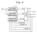
- data such as the steering wheel steering angle ⁇ sw, the vehicle speed V, the vehicle body slip angle ⁇ , and the yaw rate ⁇ are supplied to a sliding mode computing unit 24 in the computer unit 21 (step 1).
- the sliding mode computing unit 24 also receives the cornering forces Y F and Y R acting upon the front and rear axles which are detected by the cornering force sensors 18 typically consisting of resistive strain gauges attached to knuckle portions supporting the wheels, and their derivatives d Y F / dt and d Y R / dt (step 2).
- the yawing moment Mz is computed from these values (step 3), and the braking forces X R and X L which the right and left wheels should be producing are computed (step 4). Then, the liquid pressure which is to be supplied to the brake actuator 23 of each of the wheels is controlled by the braking force distribution modulator 22 (step 5).
- the vehicle body slip angle ⁇ can be also computed from the lateral acceleration YG, the vehicle speed V, and the yaw rate ⁇ .
- the cornering force can be substituted by the lateral acceleration, and the detected values of a load sensor and an acceleration sensor can be appropriately combined to obtain the vehicle body slip angle ⁇ .
- cornering forces Y F and Y R were directly obtained in the above example, but it is also possible to estimate them from the frictional coefficient ⁇ between the tires and the road surface which can be detected from the difference in the rotational speeds of the driven wheels and the non-driven wheels, the steering angles of the front and rear wheels, the vertical loads acting on the axles, and the fore-and-aft forces by using a tire model 25 ( Figure 5) consisting of a mathematical model of the dynamic properties of the tire.
- Figure 5 The block diagram of an exemplary control system for this case is shown in Figure 5.
- the fore-and-aft force is computed from a recursive computation.
- Figure 6 shows the behavior of the four wheel vehicle when no control action of the present invention was applied.
- the braking force or the fore-and-aft force X was evenly applied to the right and left wheels, and the yaw rate ⁇ and the lateral acceleration YG demonstrated divergent tendencies while the vehicle body slip angle maintained a relatively large value in one direction. This means that the vehicle body was unable to respond to the turning back of the steering wheel, and was in a spin.
- control principle may be given by the following equation.
- Mz - (L F Y F - L R Y R ) + (I/mV) ( d Y F / dt + d Y R / dt ) + I d ⁇ / dt (k + c) + I ⁇ kc
- control principle may be given by the following equation.
- Mz - (L F Y F - L R Y R ) + (I/mV) ( d Y F / dt + d Y R / dt ) + kI ⁇ (Y F + Y R )/mV - ⁇ + d ⁇ / dt (I/a) + ⁇ (kI/a)
- the control process was such that the vehicle slip angle ⁇ was kept at zero, and the yaw rate ⁇ and the lateral acceleration YG both followed the steering angle of the steering wheel.
- the coefficient a By optimally selecting the coefficient a, the change in the braking force X of each of the wheels can be made gradual (see Figure 8).
- the coefficient a By selecting a small value for the coefficient a, the vehicle slip angle ⁇ can be controlled to zero in an even better fashion depending on the responsiveness of the actuator.
- control principle may be given by the following equation.
- Mz - (L F Y F - L R Y R ) + (I/mV) ( d Y F / dt + d Y R / dt ) + kI ⁇ (Y F + Y R )/mV - ⁇
- the fore-and-aft force or the braking force or traction of the right and left wheels is controlled according to the cornering forces of the corresponding tires. Therefore, even under conditions where the gripping force of a tire is close to a limit, it is possible to improve the responsiveness and stability of the behavior of the vehicle. Further, by using the sliding mode control as described above, it is possible to improve the stability and the robustness of the control system.
- a yawing moment which a vehicle is desired to produce is computed according to a dynamic state quantity of the vehicle such as the vehicle speed and the cornering force of each of the wheels, and a braking force or a traction which is applied to each of the wheels is individually controlled so as to achieve the computed yawing moment. Therefore, even under conditions where the gripping force of the tires is close to a limit, it is possible to improve the responsiveness and stability of the behavior of the vehicle. Further, by using the sliding mode control, it is possible to improve the stability and the robustness of the control system.
Claims (8)
- Procédé de commande du comportement d'un véhicule en commandant de manière individuelle une force longitudinale (XR, XL) de chacune des roues de véhicule droites et gauches (5, 11) de manière à obtenir un comportement de véhicule souhaité, comprenant les étapes de :caractérisé en ce quecalcul d'un moment de lacet (Mz) qu'un véhicule souhaite produire en fonction d'une quantité d'état dynamique du véhicule comprenant au moins une vitesse d'avancement (V), et des forces de virage (YF, YR) que produisent les roues ; etcommande d'une force longitudinale (XR, XL) qui est appliquée à chacune des roues de manière à obtenir ledit moment de lacet calculé (Mz),
ladite force longitudinale (XR, XL) est commandée par un procédé de commande à mode par glissement utilisant une surface de glissement sur la base d'au moins une quantité d'état dynamique du véhicule. - Procédé de commande du comportement d'un véhicule selon la revendication 1, dans lequel ledit moment de lacet (Mz) est calculé de sorte qu'une réponse de taux de lacet souhaité (γ) peut être obtenue.
- Procédé de commande du comportement d'un véhicule selon la revendication 1, dans lequel ledit moment de lacet (Mz) est calculé de sorte qu'une réponse d'angle de patinage souhaité (β) peut être obtenue.
- Procédé de commande du comportement d'un véhicule selon la revendication 1, dans lequel ladite force de virage (YF, YR) est estimée à partir d'une quantité d'état dynamique du véhicule.
- Procédé de commande du comportement d'un véhicule selon la revendication 4, dans lequel ladite force de virage (YF, YR) est estimée à partir d'un coefficient de friction (µ) de la surface d'une route.
- Procédé de commande du comportement d'un véhicule selon la revendication 1, dans lequel ladite force longitudinale comprend une force de freinage (XR, XL).
- Procédé de commande du comportement d'un véhicule selon la revendication 1, dans lequel ladite force longitudinale comprend une traction.
- Système de commande du comportement d'un véhicule destiné à obtenir un comportement souhaité de véhicule en commandant de manière individuelle une force longitudinale (XR, XL) de chacune des roues droites et gauches (5, 11), comprenant :caractérisé en ce que lesdits moyens de commande de force longitudinale (S5) sont commandés par un procédé de commande à mode par glissement utilisant une surface de glissement sur la base d'au moins une quantité d'état dynamique du véhicule.des moyens (S5) destinés à commander une force longitudinale (XR, XL) qui est appliquée de manière individuelle sur chacune des roues de véhicule droites et gauches (5, 11) ;des moyens (S1) destinés à détecter une quantité d'état dynamique du véhicule comprenant au moins une vitesse d'avancement (V) ;des moyens (S2) destinés à déterminer une force de virage (YF, YR) de chacune des roues ; etdes moyens (S3) destinés à calculer un moment de lacet (Mz) que souhaite produire un véhicule en fonction de valeurs obtenues par lesdits moyens de calcul de quantité d'état dynamique (S1) et par lesdits moyens de détermination de force de virage (S2) ; dans lesquels lesdits moyens de commande de force longitudinale (S5) sont commandés en fonction d'une valeur obtenue par lesdits moyens de calcul de moment de lacet (S3),
Applications Claiming Priority (3)
| Application Number | Priority Date | Filing Date | Title |
|---|---|---|---|
| JP174217/96 | 1996-06-13 | ||
| JP17421796 | 1996-06-13 | ||
| JP17421796A JP3553735B2 (ja) | 1996-06-13 | 1996-06-13 | 車両挙動制御方法及びその装置 |
Publications (3)
| Publication Number | Publication Date |
|---|---|
| EP0812748A2 EP0812748A2 (fr) | 1997-12-17 |
| EP0812748A3 EP0812748A3 (fr) | 2000-04-26 |
| EP0812748B1 true EP0812748B1 (fr) | 2002-06-12 |
Family
ID=15974782
Family Applications (1)
| Application Number | Title | Priority Date | Filing Date |
|---|---|---|---|
| EP97106171A Expired - Lifetime EP0812748B1 (fr) | 1996-06-13 | 1997-04-15 | Méthode et système pour commander le couple de lacet d'un véhicule |
Country Status (4)
| Country | Link |
|---|---|
| US (1) | US6334656B1 (fr) |
| EP (1) | EP0812748B1 (fr) |
| JP (1) | JP3553735B2 (fr) |
| DE (1) | DE69713208T2 (fr) |
Families Citing this family (28)
| Publication number | Priority date | Publication date | Assignee | Title |
|---|---|---|---|---|
| JPH11321604A (ja) * | 1998-03-17 | 1999-11-24 | Masato Abe | 車両挙動制御における車体スリップアングルの演算方法及びその装置 |
| US6233513B1 (en) * | 1997-11-27 | 2001-05-15 | Masato Abe | Method and system for computing a vehicle body slip angle in a vehicle movement control |
| JP3458734B2 (ja) * | 1998-04-09 | 2003-10-20 | トヨタ自動車株式会社 | 車輌の運動制御装置 |
| JP3729661B2 (ja) * | 1998-09-22 | 2005-12-21 | トヨタ自動車株式会社 | 車輌の運動制御装置 |
| JP4468509B2 (ja) * | 1999-04-06 | 2010-05-26 | 本田技研工業株式会社 | 車両用操舵装置 |
| JP3623456B2 (ja) | 2001-02-28 | 2005-02-23 | トヨタ自動車株式会社 | 車輌の走行制御装置 |
| US6560524B2 (en) * | 2001-09-26 | 2003-05-06 | General Motors Corporation | Integration of rear wheel steering with vehicle stability enhancement system |
| JP3870911B2 (ja) * | 2003-02-10 | 2007-01-24 | 日産自動車株式会社 | 車線逸脱防止装置 |
| JP2004322787A (ja) * | 2003-04-23 | 2004-11-18 | Nissan Motor Co Ltd | 車線逸脱防止装置 |
| US6885931B2 (en) * | 2003-04-24 | 2005-04-26 | Visteon Global Technologies, Inc. | Control algorithm for a yaw stability management system |
| US7137673B2 (en) * | 2003-06-27 | 2006-11-21 | Visteon Global Technologies, Inc. | Vehicle yaw stability system and method |
| US20090152940A1 (en) * | 2003-08-22 | 2009-06-18 | Bombardier Recreational Products Inc. | Three-wheel vehicle electronic stability system |
| US20060180372A1 (en) * | 2003-08-22 | 2006-08-17 | Bombardier Recreational Products Inc. | Electronic stability system on a three-wheeled vehicle |
| JP4391304B2 (ja) * | 2004-04-23 | 2009-12-24 | 日産自動車株式会社 | 減速制御装置 |
| JP4638185B2 (ja) * | 2004-08-04 | 2011-02-23 | 富士重工業株式会社 | 車両の挙動制御装置 |
| CN100447533C (zh) * | 2004-11-11 | 2008-12-31 | 丰田自动车株式会社 | 滑动判定装置和滑动判定方法以及车辆 |
| US7873459B2 (en) * | 2005-07-29 | 2011-01-18 | Ford Global Technologies, Llc | Load transfer adaptive traction control system |
| US7966113B2 (en) * | 2005-08-25 | 2011-06-21 | Robert Bosch Gmbh | Vehicle stability control system |
| CN101193785B (zh) * | 2005-12-27 | 2011-07-06 | 本田技研工业株式会社 | 车辆控制装置 |
| US7641014B2 (en) * | 2006-01-31 | 2010-01-05 | Robert Bosch Gmbh | Traction control system and method |
| KR100799972B1 (ko) | 2006-12-22 | 2008-01-31 | 주식회사 만도 | 차량 자세 제어 장치의 조향 협조 제어 방법 및 그 장치 |
| JP6585444B2 (ja) * | 2015-09-25 | 2019-10-02 | Ntn株式会社 | 車両姿勢制御装置 |
| EP3501944B1 (fr) | 2017-12-20 | 2020-08-05 | Aptiv Technologies Limited | Procédé et dispositif pour estimer un couple de direction |
| CN112224214A (zh) * | 2020-10-15 | 2021-01-15 | 北京航天发射技术研究所 | 车辆速度控制方法、装置、设备及计算机可读存储介质 |
| CN113044047B (zh) * | 2021-03-31 | 2022-06-21 | 江苏大学 | 一种基于类pid-stsm的afs/dyc集成控制方法 |
| CN114194178B (zh) * | 2021-12-06 | 2023-08-29 | 尚元智行(宁波)科技有限公司 | 四轮转向四轮驱动智能底盘稳定性控制方法 |
| KR20230100509A (ko) * | 2021-12-28 | 2023-07-05 | 현대모비스 주식회사 | 4륜 조향 제어 장치 및 방법 |
| DE102022106530B3 (de) * | 2022-01-14 | 2023-05-17 | Hyundai Mobis Co., Ltd. | Unabhängiges Vierrad-Lenksystem und Verfahren zur Steuerung desselben |
Family Cites Families (22)
| Publication number | Priority date | Publication date | Assignee | Title |
|---|---|---|---|---|
| JPS61196872A (ja) * | 1985-01-24 | 1986-09-01 | Honda Motor Co Ltd | 車輛の前後輪操舵装置 |
| JPH03118618A (ja) | 1989-09-30 | 1991-05-21 | Fanuc Ltd | 制振効果を持つスライディングモード制御による制御方式 |
| JPH04126670A (ja) * | 1990-09-18 | 1992-04-27 | Nissan Motor Co Ltd | 車両の挙動制御装置 |
| DE4030653A1 (de) * | 1990-09-28 | 1992-04-02 | Bosch Gmbh Robert | Verfahren zum bestimmen der schraeglaufwinkel und/oder der seitenfuehrungskraefte eines gebremsten fahrzeuges |
| GB9026736D0 (en) | 1990-12-08 | 1991-01-30 | Vickers Systems Ltd | Sliding mode control system |
| JPH05170120A (ja) * | 1991-03-20 | 1993-07-09 | Hitachi Ltd | 車両のヨー運動量検出装置及びその方法、並びにこれを利用した車両の運動制御装置 |
| US5251137A (en) * | 1991-07-10 | 1993-10-05 | General Motors Corporation | Vehicle handling control method for antilock braking |
| US5275474A (en) * | 1991-10-04 | 1994-01-04 | General Motors Corporation | Vehicle wheel slip control on split coefficient surface |
| US5371669A (en) | 1992-06-18 | 1994-12-06 | The United States Of America As Represented By The Administrator Of The National Aeronautics And Space Administration | Sliding mode control method having terminal convergence in finite time |
| US5474369A (en) | 1993-01-13 | 1995-12-12 | Honda Giken Kogyo Kabushiki Kaisha | Braking force control system of vehicle |
| DE4305155C2 (de) * | 1993-02-19 | 2002-05-23 | Bosch Gmbh Robert | Vorrichtung zur Regelung der Fahrdynamik |
| US5417298A (en) | 1993-07-07 | 1995-05-23 | Honda Giken Kohyo Kabushiki Kaisha | Torque distribution control apparatus for vehicle |
| JP3179271B2 (ja) * | 1993-12-01 | 2001-06-25 | 本田技研工業株式会社 | 前後輪操舵装置の制御方法 |
| DE4418772C2 (de) * | 1994-05-28 | 2000-08-24 | Daimler Chrysler Ag | Verfahren zur Regelung des Bremsdrucks in Abhängigkeit der Abweichung des Istschlupfes von Rädern zu einem Sollschlupf |
| DE4418771C1 (de) * | 1994-05-28 | 1995-10-19 | Daimler Benz Ag | Verfahren zur Fahrstabilitätsregelung eines Kraftfahrzeuges bei erhöhtem Schlupf der Antriebsräder |
| JP3268124B2 (ja) * | 1994-06-27 | 2002-03-25 | 富士重工業株式会社 | 車両のトルク配分制御装置 |
| US6021367A (en) * | 1994-08-24 | 2000-02-01 | Ford Global Technologies, Inc. | Vehicle steering system and method for controlling vehicle direction through differential braking of left and right road wheels |
| US5772289A (en) * | 1994-10-11 | 1998-06-30 | Nissan Diesel Co., Ltd. | Vehicle braking force controller |
| JP3189610B2 (ja) * | 1995-02-20 | 2001-07-16 | トヨタ自動車株式会社 | 車両挙動制御装置 |
| JP3463415B2 (ja) * | 1995-06-22 | 2003-11-05 | 日産自動車株式会社 | 車両のヨーイング挙動制御装置 |
| US5899952A (en) * | 1995-12-27 | 1999-05-04 | Toyota Jidosha Kabushiki Kaisha | Device for estimating slip angle of vehicle body through interrelation thereof with yaw rate |
| DE19607185A1 (de) * | 1996-02-27 | 1997-08-28 | Bayerische Motoren Werke Ag | Verfahren zur Sicherstellung eines neutralen Fahrverhaltens bei Kurvenfahrten und gleichzeitigem Lastwechsel |
-
1996
- 1996-06-13 JP JP17421796A patent/JP3553735B2/ja not_active Expired - Fee Related
-
1997
- 1997-04-15 DE DE69713208T patent/DE69713208T2/de not_active Expired - Lifetime
- 1997-04-15 EP EP97106171A patent/EP0812748B1/fr not_active Expired - Lifetime
- 1997-05-08 US US08/848,498 patent/US6334656B1/en not_active Expired - Lifetime
Also Published As
| Publication number | Publication date |
|---|---|
| JP3553735B2 (ja) | 2004-08-11 |
| EP0812748A3 (fr) | 2000-04-26 |
| US6334656B1 (en) | 2002-01-01 |
| JPH10965A (ja) | 1998-01-06 |
| DE69713208T2 (de) | 2002-10-31 |
| DE69713208D1 (de) | 2002-07-18 |
| EP0812748A2 (fr) | 1997-12-17 |
Similar Documents
| Publication | Publication Date | Title |
|---|---|---|
| EP0812748B1 (fr) | Méthode et système pour commander le couple de lacet d'un véhicule | |
| US6892123B2 (en) | Unified control of vehicle dynamics using force and moment control | |
| EP1234741B2 (fr) | Commande de stabilité anti-renversement pour un véhicule automobile | |
| EP1627779B1 (fr) | Dispositif et procede d'estimation de performance d'adherence de pneumatique et procece de commande d'etat de fonctionnement | |
| US4794539A (en) | Propulsion control using steering angle and vehicle speed to determine tolerance range | |
| US6547343B1 (en) | Brake system control | |
| US6125319A (en) | Brake system control method responsive to measured vehicle acceleration | |
| US6035251A (en) | Brake system control method employing yaw rate and ship angle control | |
| US7143864B2 (en) | Yaw control for an automotive vehicle using steering actuators | |
| US8116942B2 (en) | Steering angle control apparatus for vehicle | |
| US6662898B1 (en) | Tire side slip angle control for an automotive vehicle using steering actuators | |
| US6360150B1 (en) | Device for controlling yawing of vehicle | |
| US6681167B2 (en) | Vehicle chassis control with coordinated brake and steering control on split coefficient surface | |
| EP1640231A1 (fr) | Reglage prédictif de la dynamique de marche d'un véhicule automobile | |
| US6813552B2 (en) | Method and apparatus for vehicle stability enhancement system | |
| US5315516A (en) | Process and system for generating a signal representative of the transverse movement of a vehicle | |
| US6840343B2 (en) | Tire side slip angle control for an automotive vehicle using steering peak seeking actuators | |
| US7433768B2 (en) | Method for determining a steering-wheel torque | |
| JP3161206B2 (ja) | 車両の旋回挙動制御装置 | |
| JP3441572B2 (ja) | 車両用タイヤ・路面間摩擦状態推定装置 | |
| JP3039071B2 (ja) | 車両旋回限界判定装置 | |
| JPH05501694A (ja) | 車両 | |
| JPH11180274A (ja) | 車両の姿勢制御装置 | |
| JP3535358B2 (ja) | 路面摩擦係数の推定装置 | |
| EP1837262A1 (fr) | Contrôle dýun véhicule à moteur utilisant une approche de réaction positive dynamique |
Legal Events
| Date | Code | Title | Description |
|---|---|---|---|
| PUAI | Public reference made under article 153(3) epc to a published international application that has entered the european phase |
Free format text: ORIGINAL CODE: 0009012 |
|
| AK | Designated contracting states |
Kind code of ref document: A2 Designated state(s): DE FR GB |
|
| PUAL | Search report despatched |
Free format text: ORIGINAL CODE: 0009013 |
|
| AK | Designated contracting states |
Kind code of ref document: A3 Designated state(s): DE FR GB |
|
| 17P | Request for examination filed |
Effective date: 20000428 |
|
| 17Q | First examination report despatched |
Effective date: 20010423 |
|
| GRAG | Despatch of communication of intention to grant |
Free format text: ORIGINAL CODE: EPIDOS AGRA |
|
| GRAG | Despatch of communication of intention to grant |
Free format text: ORIGINAL CODE: EPIDOS AGRA |
|
| GRAH | Despatch of communication of intention to grant a patent |
Free format text: ORIGINAL CODE: EPIDOS IGRA |
|
| GRAH | Despatch of communication of intention to grant a patent |
Free format text: ORIGINAL CODE: EPIDOS IGRA |
|
| GRAA | (expected) grant |
Free format text: ORIGINAL CODE: 0009210 |
|
| AK | Designated contracting states |
Kind code of ref document: B1 Designated state(s): DE FR GB |
|
| REG | Reference to a national code |
Ref country code: GB Ref legal event code: FG4D |
|
| REF | Corresponds to: |
Ref document number: 69713208 Country of ref document: DE Date of ref document: 20020718 |
|
| ET | Fr: translation filed | ||
| PLBE | No opposition filed within time limit |
Free format text: ORIGINAL CODE: 0009261 |
|
| STAA | Information on the status of an ep patent application or granted ep patent |
Free format text: STATUS: NO OPPOSITION FILED WITHIN TIME LIMIT |
|
| 26N | No opposition filed |
Effective date: 20030313 |
|
| PGFP | Annual fee paid to national office [announced via postgrant information from national office to epo] |
Ref country code: GB Payment date: 20070426 Year of fee payment: 11 |
|
| PGFP | Annual fee paid to national office [announced via postgrant information from national office to epo] |
Ref country code: FR Payment date: 20070416 Year of fee payment: 11 |
|
| GBPC | Gb: european patent ceased through non-payment of renewal fee |
Effective date: 20080415 |
|
| REG | Reference to a national code |
Ref country code: FR Ref legal event code: ST Effective date: 20081231 |
|
| PG25 | Lapsed in a contracting state [announced via postgrant information from national office to epo] |
Ref country code: FR Free format text: LAPSE BECAUSE OF NON-PAYMENT OF DUE FEES Effective date: 20080430 |
|
| PG25 | Lapsed in a contracting state [announced via postgrant information from national office to epo] |
Ref country code: GB Free format text: LAPSE BECAUSE OF NON-PAYMENT OF DUE FEES Effective date: 20080415 |
|
| PGFP | Annual fee paid to national office [announced via postgrant information from national office to epo] |
Ref country code: DE Payment date: 20130419 Year of fee payment: 17 |
|
| REG | Reference to a national code |
Ref country code: DE Ref legal event code: R119 Ref document number: 69713208 Country of ref document: DE |
|
| REG | Reference to a national code |
Ref country code: DE Ref legal event code: R119 Ref document number: 69713208 Country of ref document: DE Effective date: 20141101 |
|
| PG25 | Lapsed in a contracting state [announced via postgrant information from national office to epo] |
Ref country code: DE Free format text: LAPSE BECAUSE OF NON-PAYMENT OF DUE FEES Effective date: 20141101 |