EP1419944A1 - Zündschlosssystem für ein Kraftfahrzeug - Google Patents
Zündschlosssystem für ein Kraftfahrzeug Download PDFInfo
- Publication number
- EP1419944A1 EP1419944A1 EP03026207A EP03026207A EP1419944A1 EP 1419944 A1 EP1419944 A1 EP 1419944A1 EP 03026207 A EP03026207 A EP 03026207A EP 03026207 A EP03026207 A EP 03026207A EP 1419944 A1 EP1419944 A1 EP 1419944A1
- Authority
- EP
- European Patent Office
- Prior art keywords
- key
- ignition lock
- movement
- carrier element
- lock system
- Prior art date
- Legal status (The legal status is an assumption and is not a legal conclusion. Google has not performed a legal analysis and makes no representation as to the accuracy of the status listed.)
- Granted
Links
- 230000033001 locomotion Effects 0.000 claims abstract description 80
- 230000001960 triggered effect Effects 0.000 claims abstract description 7
- 238000011156 evaluation Methods 0.000 claims abstract description 6
- 230000006835 compression Effects 0.000 claims description 11
- 238000007906 compression Methods 0.000 claims description 11
- 230000003287 optical effect Effects 0.000 claims description 3
- 230000001953 sensory effect Effects 0.000 claims description 3
- 230000003993 interaction Effects 0.000 claims 1
- 238000009434 installation Methods 0.000 description 4
- 238000000034 method Methods 0.000 description 4
- 238000003780 insertion Methods 0.000 description 3
- 230000037431 insertion Effects 0.000 description 3
- 238000013461 design Methods 0.000 description 2
- 238000011161 development Methods 0.000 description 2
- 230000018109 developmental process Effects 0.000 description 2
- 238000011017 operating method Methods 0.000 description 2
- 208000027418 Wounds and injury Diseases 0.000 description 1
- 230000007175 bidirectional communication Effects 0.000 description 1
- 230000000903 blocking effect Effects 0.000 description 1
- 230000006378 damage Effects 0.000 description 1
- 230000001419 dependent effect Effects 0.000 description 1
- 230000000881 depressing effect Effects 0.000 description 1
- 238000010586 diagram Methods 0.000 description 1
- 238000006073 displacement reaction Methods 0.000 description 1
- 239000000428 dust Substances 0.000 description 1
- 230000000694 effects Effects 0.000 description 1
- 208000014674 injury Diseases 0.000 description 1
- 210000003127 knee Anatomy 0.000 description 1
- 238000012549 training Methods 0.000 description 1
Images


Classifications
-
- H—ELECTRICITY
- H01—ELECTRIC ELEMENTS
- H01H—ELECTRIC SWITCHES; RELAYS; SELECTORS; EMERGENCY PROTECTIVE DEVICES
- H01H13/00—Switches having rectilinearly-movable operating part or parts adapted for pushing or pulling in one direction only, e.g. push-button switch
- H01H13/50—Switches having rectilinearly-movable operating part or parts adapted for pushing or pulling in one direction only, e.g. push-button switch having a single operating member
- H01H13/56—Switches having rectilinearly-movable operating part or parts adapted for pushing or pulling in one direction only, e.g. push-button switch having a single operating member the contact returning to its original state upon the next application of operating force
- H01H13/562—Switches having rectilinearly-movable operating part or parts adapted for pushing or pulling in one direction only, e.g. push-button switch having a single operating member the contact returning to its original state upon the next application of operating force making use of a heart shaped cam
-
- B—PERFORMING OPERATIONS; TRANSPORTING
- B60—VEHICLES IN GENERAL
- B60R—VEHICLES, VEHICLE FITTINGS, OR VEHICLE PARTS, NOT OTHERWISE PROVIDED FOR
- B60R25/00—Fittings or systems for preventing or indicating unauthorised use or theft of vehicles
- B60R25/01—Fittings or systems for preventing or indicating unauthorised use or theft of vehicles operating on vehicle systems or fittings, e.g. on doors, seats or windscreens
- B60R25/04—Fittings or systems for preventing or indicating unauthorised use or theft of vehicles operating on vehicle systems or fittings, e.g. on doors, seats or windscreens operating on the propulsion system, e.g. engine or drive motor
-
- B—PERFORMING OPERATIONS; TRANSPORTING
- B60—VEHICLES IN GENERAL
- B60R—VEHICLES, VEHICLE FITTINGS, OR VEHICLE PARTS, NOT OTHERWISE PROVIDED FOR
- B60R25/00—Fittings or systems for preventing or indicating unauthorised use or theft of vehicles
- B60R25/20—Means to switch the anti-theft system on or off
- B60R25/2063—Ignition switch geometry
-
- B—PERFORMING OPERATIONS; TRANSPORTING
- B60—VEHICLES IN GENERAL
- B60R—VEHICLES, VEHICLE FITTINGS, OR VEHICLE PARTS, NOT OTHERWISE PROVIDED FOR
- B60R25/00—Fittings or systems for preventing or indicating unauthorised use or theft of vehicles
- B60R25/20—Means to switch the anti-theft system on or off
- B60R25/24—Means to switch the anti-theft system on or off using electronic identifiers containing a code not memorised by the user
- B60R25/248—Electronic key extraction prevention
Definitions
- the invention relates to an ignition lock system according to the preamble of patent claim 1.
- Ignition lock In motor vehicles, there is an electronic at high safety requirements Ignition lock, which is actuated by means of an electronic key.
- the electronic Ignition lock and the electronic key are components of the protection against unauthorized use ignition lock system.
- the ignition lock has a Pick up for the key, located in a designed as a rotor support element located.
- the rotor is by means of the key between one output and several Movement positions manually by rotation movable.
- electronic codes After a positive evaluation of a between the key and the ignition switch exchanged electronic codes at least one function that can be effected by the ignition lock, such as switching on Consumers in the vehicle, such as radio, lighting, etc., like the Starting the motor vehicle o. The like., Released.
- Rotor in the respective movement position accordingly to a switching element.
- the invention has the object of providing the ignition in such a way that this by means of a rectilinear movement of the key, in particular by the user manually, in simple way is operable.
- the carrier element in the manner of a slider linearly movable, with one and another movement position for the support element are each formed as locking positions.
- the two detent positions are through the Cooperation of a latching curve, which may be designed in the manner of a switching heart, with a locking pin engaging in the detent pin, in particular with an elastic Force is applied, fixed.
- the support element can by manual operation of the user to yet another Movement be movable, in which the motor vehicle is then started. Subsequently, after completion of the manual action, the support element from the still further movement position in the further movement position assigned Locking position automatically returned.
- the operating procedure of such a designed Ignition lock corresponds to the linear movement of that of a conventional Ignition lock, so that the ignition is largely intuitive to use by the user.
- a contour may be arranged such that the locking pin starting from the initial position along the contour always first in the one Movement position corresponding detent position is directed. This again corresponds to the conventional operating procedure. Alternatively, however, a part of the contour that is in the lane is outside the detent positions, be omitted. This will be shortly before the a movement position creates a pressure point in its overcoming and more Move the still further movement position without prior engagement in one Movement position is achievable. If the movement does not continue at the pressure point, Thus, the carrier element first returns to the one movement position. At a Embodiment according to the alternative is thus a rapid, instantaneous starting the Motor vehicle allows.
- the ignition lock has a housing with an opening for the insertion of the key.
- an opening for the insertion of the key To achieve a good seal against dust, dirt o. The like. Can the opening through be closed in the initial position of the support element. This corresponds to the Recording in the support member with the opening such that a kind of cavity in the Carrier element is formed, wherein the cavity into the interior of the housing largely is completed.
- a key movable, spring-loaded flap close the receptacle when the key is not inserted.
- a guide can still be provided in the housing for the movement of the carrier element are located so that a precise movement for the key is given.
- a pivotable locking lever is arranged on the carrier element, the is loaded with a compression spring.
- the locking lever engages by means of a cam in the A key located in a recess on the key and is still by means of a locking contour in the housing when not in the starting position befindlichem Carrier element held in the recess.
- the locking lever is in the Starting position of the support member against the force of the compression spring in an interruption on the locking contour so pivotable that the key inserted into the receptacle as well as is removable.
- the pivotable locking lever thus serves to protect the user as a trigger lock for the key from the receptacle when the support element is not in the starting position and thus the motor vehicle is in operation.
- the carrier element may have two locking levers arranged on both sides.
- a restoring force for example by means of a compression spring can be generated, in the direction of the initial position on the carrier element in the Movement.
- Switching elements are actuated by the carrier element, so that the Switching signal of the respective switching element identifies the associated function.
- the switching element is a Hall sensor, wherein the Carrier element is arranged a corresponding to the Hall sensor magnet.
- a circuit board in the housing of the ignition provides.
- the circuit board in a space-saving manner approximately parallel Arrange for leadership for the support element.
- the PCB inserted in the housing snapped, clipped o. The like. Be.
- the advantages achieved by the invention are in particular that the Ignition lock system a simple, easy-to-use linear motion sequence having.
- the ignition is simple and inexpensive.
- that is Ignition lock despite high functionality very robust and error-prone.
- the Ignition lock system can be very compact despite high functionality and safety ausgestalten and is therefore good in cramped installation spaces in the vehicle accommodate.
- the key during the driving operation of the motor vehicle in essentially completely absorbed in the ignition. This is one Risk of injury from the user's knee key in the event of an accident largely prevented.
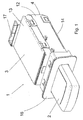
- an ignition lock system 1 for a motor vehicle which consists of a electronic ignition lock 3 and an electronic key 2 consists.
- the carrier element 6 is by means of the key 2 between a starting position s1 and one behind the other lying movement positions s2 to s5, in Fig. 5 with corresponding arrows are designated, manually movable. For this purpose, the carrier element 6 in the manner of a Slider designed linearly movable.
- the support member 6 is shown in its initial position s1, in which the key 2 in the receptacle 7 can be inserted and removed from the receptacle 7.
- the Movement position s2 and the movement position s4 for the support element 6 are respectively designed as locking positions.
- the two notches are by the Cooperation of a designed in the manner of a switching heart latching curve 8, 9 with fixed a locking pin 10.
- the locking pin 10 engages in the latching cam 8, 9 a.
- the Locking pin 10 is arranged on a sliding element 34, which in turn for Movement direction of the support member 6 is mounted transversely movable on the carrier element 6, as can be seen with reference to FIG. 8.
- the key 2 is inserted into the receptacle 7 and this is then together with the Carrier element 6 due to manual action of the user on the key 2 of the Starting position s1 brought into one of the movement positions s2 to s5, so it is between the key 2 and the ignition 3, an electronic code, and that preferably in a bidirectional communication, exchanged or transmitted.
- electronic codes i. it is the authorized key 2
- this Shared and / or triggered function may be the turning on of Consumers in the vehicle, such as the radio, lighting, etc., to start up the motor vehicle o. The like. Act.
- the electronic code for release and / or Triggering of these functions can during the movement of the support member 6 between the Starting position s1 and a movement position s2 to s5, in at least one of Movement positions or even if necessary in other positions, for example already in the starting position s1, between the key 2 and the ignition switch. 3 be replaced.
- the evaluation of the electronic code can in the ignition 3 itself or, if desired, in a separate control unit.
- the electronic code also from another identification transmitter, such as a User located, separate smart card transferable, whereby the key 2 then merely serves as a control element in the ignition lock 3 for the user.
- the support member 6 By pressing the key again 2 by the user, the support member 6, after an increased force in the vicinity of Movement position s3 is overcome, moved to the movement position s5, where the Engine of the motor vehicle is started.
- the support member 6 together with the key. 2 then stops in the movement position s4.
- the movement position s4, in which the motor vehicle is then in driving, is also shown in Fig. 3.
- the engine of the motor vehicle is stopped and the support member 6 together with the key 2 moves to the starting position s1 back. There, the key 2 then again deducted from the receptacle 7 become.
- the support member 6 together with the key 2 also in the starting position s1 be returned, in which case no engine is started.
- FIG. 6 The trajectory for the locking pin 10 in the locking curves 8, 9 in this process is shown in FIG. 6 drawn.
- the movement of the key 2 by the user necessary force is finally shown in Fig. 9.
- Fig. 9 There is also clearly the Pressure point to see the movement position s3.
- actuator 29 To start the motor vehicle in the Movement position s5 is used in Fig. 5 closer shown actuator 29.
- Das Actuator 29 consists of a holder 4 fixed in the housing 32, in a Pressure element 30 against the force of a spring 31 for switching a not further visible Switching element is movable, wherein the switching signal of this switching element then the Startup process if the code is allowed.
- the pressure element 30 is in turn of Carrier element 6 moves in the movement position s5.
- the support element 6 by manual movement by means of Key 2 can be moved to the movement position s5, in which the motor vehicle started becomes. From the movement position s5, the carrier element 6 is then, after End of manual intervention of the user on the key 2, in which the Movement position s4 assigned detent automatically returned. Between two locking curves 8, 9 is a visible in Fig. 6 contour 11 is arranged such that the Locking pin 10 starting from the initial position s1 along the contour first in the first detent position corresponding movement position s2 is directed. Starting from the Starting position s1 is the engine start due to the contour 11 only twice Operation of the key 2 by the user possible. Alternatively is also one Design conceivable, which starting the engine already by pressing once Key 2 and overcoming the pressure point allows. In this case, the part 11 'of the Contour 11 omitted, which is also shown in Fig. 6. This makes it possible without to get into the movement position s2, the support member 6 directly into the Movement position s5 to start the motor vehicle to move on.
- the ignition lock 3 as already mentioned and in Fig. 4th shown, a housing 4, in detail from a base frame 12, a lid 13 and a bottom 14 is.
- the housing 4 has at its base frame 12, the opening fifth on.
- the opening 5 is through the support member 6 itself in its starting position closed by the cavity-like receptacle 7 in the support member 6 with the opening. 5 corresponds.
- the recording 7 can still be closed by means of a movable and spring-loaded flap 15, the in Fig. 4 to see is.
- the flap 15 is upon insertion of the key 2 in the opening 5 after a Moved page and then gives the recording 7 to fully insert the key 2 free.
- the receptacle 7 for the key 2 and the opening 5 is of a Frame 16 framed, which is latched onto the housing 4, so as to corresponding Cutouts in the instrument panel of the motor vehicle after installation of the ignition lock. 3 to cover up.
- the electrical connection of the ignition lock 3 in the motor vehicle via a female connector 17 on the housing 4.
- In the housing 4 is a visible in Fig. 5 Guide 18 for the linear movement of designed as a slide carrier element 6.
- a Compression spring 19 finally serves to generate a toward the starting position s1 acting restoring force for the carrier element 6 during its movement.
- the key 2 is only in the starting position s1 from the Take 7 removable by this outside the initial position s1 of the Carrier element 6 is locked in the receptacle 7.
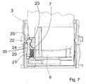
- the closer design of the catch of the key 2 is shown in Fig. 7.
- a latching lever 20 is pivotally arranged for latching.
- the Locking lever 20 is loaded with a compression spring 21, that the locking lever 20 in the direction is pivoted to the recording 7.
- the switching element as a Hall sensor 27th formed and the support member 6 is located to switch the Hall sensor 27 a to Hall sensor 27 corresponding magnet 28, as shown in Fig. 8.
- the switching element at the bottom in Housing 4, in the bottom 14, there is a particular visible in Fig. 8, in approximately parallel to the guide 18 for the support member 6 arranged circuit board 26, the receives electrical and / or electronic components. These components are those necessary for operation of the ignition lock 3.
- the Hall sensors 27, the switching elements o. The like.
- Die Circuit board 26 can be inserted in the housing 4, snapped, clipped o. The like. Be.
- the invention is not limited to the embodiment described and illustrated limited. Rather, it also includes all professional training in the context of invention defined by the claims. So the invention can not only Ignition lock systems for any vehicle use, but also to other locks, such as those on work machines, real estate o. The like. are arranged to be used.
Landscapes
- Engineering & Computer Science (AREA)
- Mechanical Engineering (AREA)
- Lock And Its Accessories (AREA)
Abstract
Description
- Fig. 1
- ein Zündschloßsystem für ein Kraftfahrzeug bestehend aus einem Zündschloß mit einem eingesteckten Schlüssel in perspektivischer Ansicht, wobei der Schlüssel in Ausgangsstellung befindlich ist,
- Fig. 2
- das Zündschloßsystem wie in Fig. 1, wobei der Schlüssel in einer Bewegungsstellung befindlich ist,
- Fig. 3
- das Zündschloßsystem wie in Fig. 1, wobei der Schlüssel in einer anderen Bewegungsstellung befindlich ist,
- Fig. 4
- das Zündschloß aus Fig. 1 ohne Schlüssel,
- Fig. 5
- das Zündschloßsystem wie in Fig. 1, wobei jedoch das Gehäuse des Zündschlosses geöffnet ist, und wobei teilweise verdeckt liegende Teile sichtbar sind,
- Fig. 6
- einen vergrößerten Ausschnitt aus Fig. 5 im Bereich der Rastkurven,
- Fig. 7
- eine vergrößerte Detailansicht aus Fig. 5 im Bereich des Rasthebels,
- Fig. 8
- den Boden des geöffneten Gehäuses für das Zündschloß und
- Fig. 9
- ein Kraft-Weg-Diagramm für die Bewegung des Schlüssels im Zündschloß.
- 1:
- Zündschloßsystem
- 2:
- Schlüssel
- 3:
- Zündschloß
- 4:
- Gehäuse
- 5:
- Öffnung (im Gehäuse)
- 6:
- Trägerelement
- 7:
- Aufnahme
- 8,9:
- Rastkurve
- 10:
- Raststift
- 11:
- Kontur
- 11':
- Teil (der Kontur)
- 12:
- Grundrahmen (von Gehäuse)
- 13:
- Deckel (von Gehäuse)
- 14:
- Boden (von Gehäuse)
- 15:
- Klappe
- 16:
- Blende
- 17:
- Steckerbuchse
- 18:
- Führung
- 19:
- Druckfeder (am Trägerelement)
- 20:
- Rasthebel
- 21:
- Druckfeder (am Rasthebel)
- 22:
- Nocken (am Rasthebel)
- 23:
- Ausnehmung (am Schlüssel)
- 24:
- Fläche (an Nocken)
- 25:
- Unterbrechung (in Sperrkontur)
- 26:
- Leiterplatte
- 27:
- Hallsensor
- 28:
- Magnet
- 29:
- Betätigungselement (für Startvorgang des Kraftfahrzeugs)
- 30:
- Druckelement (von Betätigungselement)
- 31:
- Feder (für Druckelement)
- 32:
- Halterung (für Druckelement)
- 33:
- Sperrkontur
- 34:
- Schiebeelement (für Raststift)
- 35:
- Feder (für Raststift)
Claims (10)
- Zündschloßsystem, insbesondere in einem Kraftfahrzeug, mit einem elektronischen Zündschloß (3) sowie mit einem elektronischen Schlüssel (2), wobei das Zündschloß (3) eine in einem Trägerelement (6) befindliche Aufnahme (7) für den Schlüssel (2) aufweist, wobei das Trägerelement (6) mittels des Schlüssels (2) zwischen einer Ausgangsstellung (s1) und Bewegungsstellungen (s2, s3, s4, s5) bewegbar ist, wobei insbesondere zwischen dem Schlüssel (2) und dem Zündschloß (3) ein elektronischer Code austauschbar ist, und wobei nach positiver Auswertung des Codes wenigstens eine vom Zündschloß (3) bewirkbare Funktion, wie das Einschalten von Verbrauchern im Kraftfahrzeug, das Starten des Kraftfahrzeugs o. dgl., freigegeben ist und/oder ausgelöst wird, dadurch gekennzeichnet, daß das Trägerelement (6) in der Art eines Schiebers linear beweglich ist, daß eine Bewegungsstellung (s2) sowie eine weitere Bewegungsstellung (s4) für das Trägerelement (6) jeweils als Raststellungen ausgebildet sind, und daß die beiden Raststellungen durch das Zusammenwirken einer, insbesondere in der Art eines Schaltherzens ausgestalteten Rastkurve (8, 9) mit einem in die Rastkurve (8, 9) eingreifenden, insbesondere mit einer elastischen Kraft beaufschlagten Raststift (10) festgelegt sind.
- Zündschloßsystem nach Anspruch 1, dadurch gekennzeichnet, daß die beiden Rastkurven (8, 9) in Bewegungsrichtung des Trägerelements (6) hintereinander angeordnet sind.
- Zündschloßsystem nach Anspruch 1 oder 2, dadurch gekennzeichnet, daß das Trägerelement (6) durch Bewegung bis in noch eine weitere Bewegungsstellung (s5), in der das Kraftfahrzeug gestartet wird, insbesondere manuell bewegbar ist, und daß vorzugsweise das Trägerelement (6) aus der noch weiteren Bewegungsstellung (s5) in die der weiteren Bewegungsstellung (s4) zugeordnete Raststellung, insbesondere nach Beendigung der manuellen Einwirkung selbsttätig, zurückgeführt wird.
- Zündschloßsystem nach Anspruch 1, 2 oder 3, dadurch gekennzeichnet, daß zwischen den beiden Rastkurven (8, 9) eine Kontur (11) derart angeordnet ist, daß der Raststift (10) ausgehend von der Ausgangsstellung (s1) entlang der Kontur (11) zunächst in die der einen Bewegungsstellung (s2) entsprechende Raststellung gelenkt wird.
- Zündschloßsystem nach einem der Ansprüche 1 bis 4, dadurch gekennzeichnet, daß das Zündschloß (3) ein Gehäuse (4) mit einer Öffnung (5) aufweist, daß vorzugsweise die Öffnung (5) durch das Trägerelement (6) in dessen Ausgangsstellung (s1) verschlossen ist, indem die beispielsweise hohlraumartige Aufnahme (7) im Trägerelement (6) mit der Öffnung (5) korrespondiert, daß weiter vorzugsweise eine vom Schlüssel (2) bewegliche Klappe (15), die insbesondere federbelastet ausgestaltet ist, die Aufnahme (7) verschließt, und daß noch weiter vorzugsweise im Gehäuse (4) eine Führung (18) für die Bewegung des Trägerelements (6) befindlich ist.
- Zündschloßsystem nach einem der Ansprüche 1 bis 5, dadurch gekennzeichnet, daß am Trägerelement (6) ein, insbesondere mit einer Druckfeder (21) belasteter, verschwenkbarer Rasthebel (20) angeordnet ist, gegebenenfalls zwei Rasthebel (20) beidseitig angeordnet sind, wobei vorzugsweise der Rasthebel (20) mittels eines Nockens (22) bei in der Aufnahme (7) befindlichem Schlüssel (2) in eine Ausnehmung (23) am Schlüssel (2) eingreift, sowie insbesondere mittels einer Sperrkontur (33) im Gehäuse (4) bei nicht in der Ausgangsstellung (s1) befindlichem Trägerelement (6) in der Ausnehmung (23) in der Art einer Abzugssicherung für den Schlüssel (2) festgehalten ist, und wobei weiter vorzugsweise der Rasthebel (20) in der Ausgangsstellung (s1) des Trägerelements (6) gegen die Kraft der Druckfeder (21) in eine Unterbrechung (25) an der Sperrkontur (33) derart verschwenkbar ist, daß der Schlüssel (2) in die Aufnahme (7) einführbar sowie entnehmbar ist.
- Zündschloßsystem nach einem der Ansprüche 1 bis 6, dadurch gekennzeichnet, daß eine Rückstellkraft, die insbesondere mittels einer Druckfeder (19) erzeugt ist, in Richtung auf die Ausgangsstellung (s1) auf das Trägerelement (6) bei dessen Bewegung einwirkt.
- Zündschloßsystem nach einem der Ansprüche 1 bis 7, dadurch gekennzeichnet, daß das Trägerelement (6) in wenigstens einer Bewegungsstellung (s3, s5) ein elektrisches, elektronisches, optisches, sensorisches o. dgl. Schaltelement betätigt, dessen Schaltsignal insbesondere die vom Zündschloß (3) bewirkbare Funktion kennzeichnet, daß vorzugsweise das Schaltelement als Hallsensor (27) ausgebildet ist, und daß weiter vorzugsweise am Trägerelement (6) ein zum Hallsensor (27) korrespondierender Magnet (28) angeordnet ist.
- Zündschloßsystem nach einem der Ansprüche 1 bis 8, dadurch gekennzeichnet, daß im Gehäuse (4) eine Leiterplatte (26) zur Aufnahme der elektrischen und/oder elektronischen Bauteile, wie des Schaltelements, des Hallsensors (27) o. dgl., insbesondere in etwa parallel zur Führung (18) für das Trägerelement (6), angeordnet ist, und daß vorzugsweise die Leiterplatte (26) im Gehäuse (4) eingelegt, eingerastet, eingeclipst o. dgl. ist.
- Zündschloßsystem nach einem der Ansprüche 1 bis 9, dadurch gekennzeichnet, daß die Aufnahme (7) durch eine Blende (16) umrahmt ist, wobei insbesondere die Blende (16) auf das Gehäuse (4) aufgerastet ist.
Applications Claiming Priority (2)
| Application Number | Priority Date | Filing Date | Title |
|---|---|---|---|
| DE10253520 | 2002-11-16 | ||
| DE10253520 | 2002-11-16 |
Publications (2)
| Publication Number | Publication Date |
|---|---|
| EP1419944A1 true EP1419944A1 (de) | 2004-05-19 |
| EP1419944B1 EP1419944B1 (de) | 2006-01-18 |
Family
ID=32115555
Family Applications (1)
| Application Number | Title | Priority Date | Filing Date |
|---|---|---|---|
| EP03026207A Expired - Lifetime EP1419944B1 (de) | 2002-11-16 | 2003-11-14 | Zündschlosssystem für ein Kraftfahrzeug |
Country Status (3)
| Country | Link |
|---|---|
| EP (1) | EP1419944B1 (de) |
| AT (1) | ATE316024T1 (de) |
| DE (2) | DE10353195A1 (de) |
Cited By (4)
| Publication number | Priority date | Publication date | Assignee | Title |
|---|---|---|---|---|
| EP1826077A1 (de) * | 2006-02-24 | 2007-08-29 | Volkswagen Aktiengesellschaft | Zündschloss mit verbesserter Manipulationssicherheit |
| DE102008003969A1 (de) | 2007-01-16 | 2008-07-24 | Lear Corporation, Southfield | Elektronischer Fahrzeugschlüssel und Gehäuseanordnung |
| GB2474391A (en) * | 2006-04-07 | 2011-04-13 | Aston Martin Lagonda Ltd | Docking station with latching mechanism for electronic key fob. |
| WO2021127753A1 (en) * | 2019-12-26 | 2021-07-01 | U-Shin Do Brasil Sistemas Automotivos Ltda. | Vehicle ignition control unit |
Families Citing this family (11)
| Publication number | Priority date | Publication date | Assignee | Title |
|---|---|---|---|---|
| DE102005003858A1 (de) * | 2005-01-27 | 2006-08-03 | Leopold Kostal Gmbh & Co. Kg | Zündschloßsystem für ein Kraftfahrzeug |
| DE102005011782A1 (de) | 2005-03-11 | 2006-09-14 | Marquardt Gmbh | Zündschlosssystem für ein Kraftfahrzeug |
| DE102005038437A1 (de) * | 2005-08-12 | 2007-02-15 | Huf Hülsbeck & Fürst GmbH & Co KG | Zündvorrichtung für einen Motor, insbesondere in einem Kraftfahrzeug |
| DE102005043232A1 (de) * | 2005-09-09 | 2007-03-15 | Bayerische Motoren Werke Ag | Vorrichtung zum Starten des Motors eines Kraftfahrzeugs |
| DE102005062162A1 (de) * | 2005-12-22 | 2007-06-28 | Huf Hülsbeck & Fürst Gmbh & Co. Kg | Zünd-Anlaß-Schaltereinrichtung |
| DE102006008624A1 (de) * | 2006-02-24 | 2007-08-30 | Marquardt Gmbh | Sperrvorrichtung für ein bewegliches Element |
| US7617708B2 (en) | 2006-07-28 | 2009-11-17 | Volkswagen Ag | Ignition lock for a motor vehicle and method of operating an ignition lock system |
| DE102007022248A1 (de) * | 2007-05-09 | 2008-11-13 | Huf Hülsbeck & Fürst Gmbh & Co. Kg | Vorrichtung zur Aufnahme eines elektronischen Schlüssels |
| DE102007043039B4 (de) | 2007-09-11 | 2019-12-19 | Huf Hülsbeck & Fürst Gmbh & Co. Kg | Vorrichtung zur Aufnahme eines elektronischen Schlüssels |
| DE102007054473A1 (de) * | 2007-11-13 | 2009-05-14 | Huf Hülsbeck & Fürst Gmbh & Co. Kg | Vorrichtung zur Aufnahme eines elektronischen Schlüssels |
| DE102009039142A1 (de) * | 2009-08-27 | 2011-03-03 | GM Global Technology Operations, Inc., Detroit | Bedienteil für ein Kraftfahrzeug |
Citations (2)
| Publication number | Priority date | Publication date | Assignee | Title |
|---|---|---|---|---|
| DE19939733A1 (de) * | 1999-08-21 | 2001-03-29 | Huf Huelsbeck & Fuerst Gmbh | Vorrichtung zum Zünden eines Fahrzeugmotors mittels eines elektronischen Schlüssels |
| EP1279576A2 (de) * | 2001-07-25 | 2003-01-29 | Marquardt GmbH | Zündschlosssystem für ein Kraftfahrzeug |
-
2003
- 2003-11-13 DE DE10353195A patent/DE10353195A1/de not_active Withdrawn
- 2003-11-14 AT AT03026207T patent/ATE316024T1/de not_active IP Right Cessation
- 2003-11-14 DE DE50302224T patent/DE50302224D1/de not_active Expired - Lifetime
- 2003-11-14 EP EP03026207A patent/EP1419944B1/de not_active Expired - Lifetime
Patent Citations (2)
| Publication number | Priority date | Publication date | Assignee | Title |
|---|---|---|---|---|
| DE19939733A1 (de) * | 1999-08-21 | 2001-03-29 | Huf Huelsbeck & Fuerst Gmbh | Vorrichtung zum Zünden eines Fahrzeugmotors mittels eines elektronischen Schlüssels |
| EP1279576A2 (de) * | 2001-07-25 | 2003-01-29 | Marquardt GmbH | Zündschlosssystem für ein Kraftfahrzeug |
Cited By (5)
| Publication number | Priority date | Publication date | Assignee | Title |
|---|---|---|---|---|
| EP1826077A1 (de) * | 2006-02-24 | 2007-08-29 | Volkswagen Aktiengesellschaft | Zündschloss mit verbesserter Manipulationssicherheit |
| GB2474391A (en) * | 2006-04-07 | 2011-04-13 | Aston Martin Lagonda Ltd | Docking station with latching mechanism for electronic key fob. |
| GB2474391B (en) * | 2006-04-07 | 2011-06-01 | Aston Martin Lagonda Ltd | Docking station for an electronic key fob |
| DE102008003969A1 (de) | 2007-01-16 | 2008-07-24 | Lear Corporation, Southfield | Elektronischer Fahrzeugschlüssel und Gehäuseanordnung |
| WO2021127753A1 (en) * | 2019-12-26 | 2021-07-01 | U-Shin Do Brasil Sistemas Automotivos Ltda. | Vehicle ignition control unit |
Also Published As
| Publication number | Publication date |
|---|---|
| DE10353195A1 (de) | 2004-08-12 |
| EP1419944B1 (de) | 2006-01-18 |
| ATE316024T1 (de) | 2006-02-15 |
| DE50302224D1 (de) | 2006-04-06 |
Similar Documents
| Publication | Publication Date | Title |
|---|---|---|
| EP1279576B1 (de) | Zündschlosssystem für ein Kraftfahrzeug | |
| EP1419944B1 (de) | Zündschlosssystem für ein Kraftfahrzeug | |
| EP1737713B1 (de) | Vorrichtung zum starten eines fahrzeugmotors mittels eines elektronischen schlüssels und ein dazu zu verwendender schlüssel | |
| EP1135284B1 (de) | Schliessystem, insbesondere für kraftfahrzeuge | |
| EP1177942B1 (de) | Rückstelleinrichtung für einen Schalter eines Kraftfahrzeuges | |
| DE19751805C1 (de) | Elektronisches Zündschloßsystem, insbesondere für Kraftfahrzeuge | |
| WO2005052970A1 (de) | Schaltvorrichtung und anordnung zur erfassung unterschiedlicher positionen eines türelements | |
| DE102004013198A1 (de) | Zündschloßsystem für ein Kraftfahrzeug | |
| EP3621855B1 (de) | Verriegelungseinrichtung, insbesondere für ein kraftfahrzeug | |
| EP3227147B1 (de) | Verriegelungseinrichtung für ein kraftfahrzeug | |
| EP1700760B1 (de) | Zündschlosssystem für ein Kraftfahrzeug | |
| WO2002027123A1 (de) | Zündschloss für ein kraftfahrzeug | |
| EP1434706B1 (de) | Zündschloss | |
| DE19921889B4 (de) | Zündschloß für ein Kraftfahrzeug | |
| EP1607289B1 (de) | Zündschloss für ein Kraftfahrzeug | |
| DE60129859T2 (de) | Vorrichtung zum Austausch von Daten, die teils repräsentativ für mindestens einen berechtigten Kraftfahrzeug-Benutzer sind | |
| EP1048526B1 (de) | Für ein Kraftfahrzeug bestimmtes Einbaugerät | |
| DE19838992A1 (de) | Zündanlaßschalter für Kraftfahrzeuge mit elektronischer Lenkungsverriegelung | |
| DE10106123B4 (de) | Elektrisches/elektronisches Schaltsystem für Kraftfahrzeuge | |
| DE10143804B4 (de) | Zündschloß für ein Kraftfahrzeug | |
| DE19809062A1 (de) | Verfahren zum Steuern eines fremdkraftbetätigt zu öffnenden Daches eines Fahrzeuges mit einer Betätigungseinrichtung | |
| EP2036790B1 (de) | Zündschloss für ein Kraftfahrzeug | |
| DE102005028097A1 (de) | Zündschloß für ein Kraftfahrzeug | |
| EP2231970B1 (de) | Aktuator für einen elektromechanischen drehschliesszylinder und einen elektromechanischen drehschliesszylinder mit einem solchen aktuator | |
| DE102005037440A1 (de) | Zündschloß für ein Kraftfahrzeug |
Legal Events
| Date | Code | Title | Description |
|---|---|---|---|
| PUAI | Public reference made under article 153(3) epc to a published international application that has entered the european phase |
Free format text: ORIGINAL CODE: 0009012 |
|
| AK | Designated contracting states |
Kind code of ref document: A1 Designated state(s): AT BE BG CH CY CZ DE DK EE ES FI FR GB GR HU IE IT LI LU MC NL PT RO SE SI SK TR |
|
| AX | Request for extension of the european patent |
Extension state: AL LT LV MK |
|
| 17P | Request for examination filed |
Effective date: 20040910 |
|
| 17Q | First examination report despatched |
Effective date: 20041018 |
|
| AKX | Designation fees paid |
Designated state(s): AT BE BG CH CY CZ DE DK EE ES FI FR GB GR HU IE IT LI LU MC NL PT RO SE SI SK TR |
|
| GRAP | Despatch of communication of intention to grant a patent |
Free format text: ORIGINAL CODE: EPIDOSNIGR1 |
|
| GRAS | Grant fee paid |
Free format text: ORIGINAL CODE: EPIDOSNIGR3 |
|
| GRAA | (expected) grant |
Free format text: ORIGINAL CODE: 0009210 |
|
| AK | Designated contracting states |
Kind code of ref document: B1 Designated state(s): AT BE BG CH CY CZ DE DK EE ES FI FR GB GR HU IE IT LI LU MC NL PT RO SE SI SK TR |
|
| PG25 | Lapsed in a contracting state [announced via postgrant information from national office to epo] |
Ref country code: IT Free format text: LAPSE BECAUSE OF FAILURE TO SUBMIT A TRANSLATION OF THE DESCRIPTION OR TO PAY THE FEE WITHIN THE PRESCRIBED TIME-LIMIT;WARNING: LAPSES OF ITALIAN PATENTS WITH EFFECTIVE DATE BEFORE 2007 MAY HAVE OCCURRED AT ANY TIME BEFORE 2007. THE CORRECT EFFECTIVE DATE MAY BE DIFFERENT FROM THE ONE RECORDED. Effective date: 20060118 Ref country code: SI Free format text: LAPSE BECAUSE OF FAILURE TO SUBMIT A TRANSLATION OF THE DESCRIPTION OR TO PAY THE FEE WITHIN THE PRESCRIBED TIME-LIMIT Effective date: 20060118 Ref country code: SK Free format text: LAPSE BECAUSE OF FAILURE TO SUBMIT A TRANSLATION OF THE DESCRIPTION OR TO PAY THE FEE WITHIN THE PRESCRIBED TIME-LIMIT Effective date: 20060118 Ref country code: RO Free format text: LAPSE BECAUSE OF FAILURE TO SUBMIT A TRANSLATION OF THE DESCRIPTION OR TO PAY THE FEE WITHIN THE PRESCRIBED TIME-LIMIT Effective date: 20060118 Ref country code: FI Free format text: LAPSE BECAUSE OF FAILURE TO SUBMIT A TRANSLATION OF THE DESCRIPTION OR TO PAY THE FEE WITHIN THE PRESCRIBED TIME-LIMIT Effective date: 20060118 Ref country code: GB Free format text: LAPSE BECAUSE OF FAILURE TO SUBMIT A TRANSLATION OF THE DESCRIPTION OR TO PAY THE FEE WITHIN THE PRESCRIBED TIME-LIMIT Effective date: 20060118 Ref country code: IE Free format text: LAPSE BECAUSE OF FAILURE TO SUBMIT A TRANSLATION OF THE DESCRIPTION OR TO PAY THE FEE WITHIN THE PRESCRIBED TIME-LIMIT Effective date: 20060118 Ref country code: NL Free format text: LAPSE BECAUSE OF FAILURE TO SUBMIT A TRANSLATION OF THE DESCRIPTION OR TO PAY THE FEE WITHIN THE PRESCRIBED TIME-LIMIT Effective date: 20060118 |
|
| REG | Reference to a national code |
Ref country code: GB Ref legal event code: FG4D Free format text: NOT ENGLISH |
|
| REG | Reference to a national code |
Ref country code: CH Ref legal event code: EP |
|
| REG | Reference to a national code |
Ref country code: IE Ref legal event code: FG4D Free format text: LANGUAGE OF EP DOCUMENT: GERMAN |
|
| REF | Corresponds to: |
Ref document number: 50302224 Country of ref document: DE Date of ref document: 20060406 Kind code of ref document: P |
|
| PG25 | Lapsed in a contracting state [announced via postgrant information from national office to epo] |
Ref country code: SE Free format text: LAPSE BECAUSE OF FAILURE TO SUBMIT A TRANSLATION OF THE DESCRIPTION OR TO PAY THE FEE WITHIN THE PRESCRIBED TIME-LIMIT Effective date: 20060418 Ref country code: DK Free format text: LAPSE BECAUSE OF FAILURE TO SUBMIT A TRANSLATION OF THE DESCRIPTION OR TO PAY THE FEE WITHIN THE PRESCRIBED TIME-LIMIT Effective date: 20060418 Ref country code: BG Free format text: LAPSE BECAUSE OF FAILURE TO SUBMIT A TRANSLATION OF THE DESCRIPTION OR TO PAY THE FEE WITHIN THE PRESCRIBED TIME-LIMIT Effective date: 20060418 |
|
| PG25 | Lapsed in a contracting state [announced via postgrant information from national office to epo] |
Ref country code: ES Free format text: LAPSE BECAUSE OF FAILURE TO SUBMIT A TRANSLATION OF THE DESCRIPTION OR TO PAY THE FEE WITHIN THE PRESCRIBED TIME-LIMIT Effective date: 20060429 |
|
| PG25 | Lapsed in a contracting state [announced via postgrant information from national office to epo] |
Ref country code: PT Free format text: LAPSE BECAUSE OF FAILURE TO SUBMIT A TRANSLATION OF THE DESCRIPTION OR TO PAY THE FEE WITHIN THE PRESCRIBED TIME-LIMIT Effective date: 20060619 |
|
| NLV1 | Nl: lapsed or annulled due to failure to fulfill the requirements of art. 29p and 29m of the patents act | ||
| GBV | Gb: ep patent (uk) treated as always having been void in accordance with gb section 77(7)/1977 [no translation filed] |
Effective date: 20060118 |
|
| ET | Fr: translation filed | ||
| REG | Reference to a national code |
Ref country code: IE Ref legal event code: FD4D |
|
| PLBE | No opposition filed within time limit |
Free format text: ORIGINAL CODE: 0009261 |
|
| STAA | Information on the status of an ep patent application or granted ep patent |
Free format text: STATUS: NO OPPOSITION FILED WITHIN TIME LIMIT |
|
| PG25 | Lapsed in a contracting state [announced via postgrant information from national office to epo] |
Ref country code: MC Free format text: LAPSE BECAUSE OF NON-PAYMENT OF DUE FEES Effective date: 20061130 Ref country code: BE Free format text: LAPSE BECAUSE OF NON-PAYMENT OF DUE FEES Effective date: 20061130 |
|
| 26N | No opposition filed |
Effective date: 20061019 |
|
| BERE | Be: lapsed |
Owner name: MARQUARDT G.M.B.H. Effective date: 20061130 Owner name: VOLKSWAGEN A.G. Effective date: 20061130 |
|
| PG25 | Lapsed in a contracting state [announced via postgrant information from national office to epo] |
Ref country code: AT Free format text: LAPSE BECAUSE OF NON-PAYMENT OF DUE FEES Effective date: 20061114 |
|
| PG25 | Lapsed in a contracting state [announced via postgrant information from national office to epo] |
Ref country code: CZ Free format text: LAPSE BECAUSE OF FAILURE TO SUBMIT A TRANSLATION OF THE DESCRIPTION OR TO PAY THE FEE WITHIN THE PRESCRIBED TIME-LIMIT Effective date: 20060118 Ref country code: GR Free format text: LAPSE BECAUSE OF FAILURE TO SUBMIT A TRANSLATION OF THE DESCRIPTION OR TO PAY THE FEE WITHIN THE PRESCRIBED TIME-LIMIT Effective date: 20060419 |
|
| PG25 | Lapsed in a contracting state [announced via postgrant information from national office to epo] |
Ref country code: EE Free format text: LAPSE BECAUSE OF FAILURE TO SUBMIT A TRANSLATION OF THE DESCRIPTION OR TO PAY THE FEE WITHIN THE PRESCRIBED TIME-LIMIT Effective date: 20060118 |
|
| PG25 | Lapsed in a contracting state [announced via postgrant information from national office to epo] |
Ref country code: LI Free format text: LAPSE BECAUSE OF NON-PAYMENT OF DUE FEES Effective date: 20071130 Ref country code: CH Free format text: LAPSE BECAUSE OF NON-PAYMENT OF DUE FEES Effective date: 20071130 Ref country code: TR Free format text: LAPSE BECAUSE OF FAILURE TO SUBMIT A TRANSLATION OF THE DESCRIPTION OR TO PAY THE FEE WITHIN THE PRESCRIBED TIME-LIMIT Effective date: 20060118 Ref country code: HU Free format text: LAPSE BECAUSE OF FAILURE TO SUBMIT A TRANSLATION OF THE DESCRIPTION OR TO PAY THE FEE WITHIN THE PRESCRIBED TIME-LIMIT Effective date: 20060719 Ref country code: LU Free format text: LAPSE BECAUSE OF NON-PAYMENT OF DUE FEES Effective date: 20061114 |
|
| REG | Reference to a national code |
Ref country code: CH Ref legal event code: PL |
|
| PG25 | Lapsed in a contracting state [announced via postgrant information from national office to epo] |
Ref country code: CY Free format text: LAPSE BECAUSE OF FAILURE TO SUBMIT A TRANSLATION OF THE DESCRIPTION OR TO PAY THE FEE WITHIN THE PRESCRIBED TIME-LIMIT Effective date: 20060118 |
|
| REG | Reference to a national code |
Ref country code: FR Ref legal event code: PLFP Year of fee payment: 13 |
|
| REG | Reference to a national code |
Ref country code: FR Ref legal event code: PLFP Year of fee payment: 14 |
|
| REG | Reference to a national code |
Ref country code: FR Ref legal event code: PLFP Year of fee payment: 15 |
|
| PGFP | Annual fee paid to national office [announced via postgrant information from national office to epo] |
Ref country code: FR Payment date: 20171121 Year of fee payment: 15 Ref country code: DE Payment date: 20171214 Year of fee payment: 15 |
|
| REG | Reference to a national code |
Ref country code: DE Ref legal event code: R119 Ref document number: 50302224 Country of ref document: DE |
|
| PG25 | Lapsed in a contracting state [announced via postgrant information from national office to epo] |
Ref country code: FR Free format text: LAPSE BECAUSE OF NON-PAYMENT OF DUE FEES Effective date: 20181130 Ref country code: DE Free format text: LAPSE BECAUSE OF NON-PAYMENT OF DUE FEES Effective date: 20190601 |