EP1419937B1 - Stirnseitig an einem Motorträger anbringbarer Adapter - Google Patents
Stirnseitig an einem Motorträger anbringbarer Adapter Download PDFInfo
- Publication number
- EP1419937B1 EP1419937B1 EP20030025639 EP03025639A EP1419937B1 EP 1419937 B1 EP1419937 B1 EP 1419937B1 EP 20030025639 EP20030025639 EP 20030025639 EP 03025639 A EP03025639 A EP 03025639A EP 1419937 B1 EP1419937 B1 EP 1419937B1
- Authority
- EP
- European Patent Office
- Prior art keywords
- adapter
- flange
- adapter according
- collar
- engine bearer
- Prior art date
- Legal status (The legal status is an assumption and is not a legal conclusion. Google has not performed a legal analysis and makes no representation as to the accuracy of the status listed.)
- Expired - Lifetime
Links
Images


Classifications
-
- B—PERFORMING OPERATIONS; TRANSPORTING
- B60—VEHICLES IN GENERAL
- B60R—VEHICLES, VEHICLE FITTINGS, OR VEHICLE PARTS, NOT OTHERWISE PROVIDED FOR
- B60R19/00—Wheel guards; Radiator guards, e.g. grilles; Obstruction removers; Fittings damping bouncing force in collisions
- B60R19/02—Bumpers, i.e. impact receiving or absorbing members for protecting vehicles or fending off blows from other vehicles or objects
- B60R19/24—Arrangements for mounting bumpers on vehicles
Definitions
- the invention relates to a front side attachable to a motor mount adapter according to the preamble of claim 1.
- US-A-5080410 shows an adapter, the features of the preamble of claims 1 and 2 having.
- the object of the invention is to provide an adapter that in a simple way an engine mount is attachable to a front end or bumper fastened is, and which is inexpensive to produce.
- the adapter is a sheet-metal forming part.
- Leave sheet metal formed parts Produce quickly and easily and require no significant rework.
- sheet metal stampings have only very small tolerances, so that the Front end or the bumper mounted with correspondingly small tolerances can be.
- the adapter has a flange with which the adapter can be pushed positively over the motor carrier or inserted into the motor carrier.
- the insertion into the engine mount suspends a motor bracket in shell construction two shells ahead.
- the adapter is then usually in the first shell inserted before the second shell is joined. But he can also finish in the assembled engine carrier in shell construction inserted from the front become. This insertion is also considered insertion.
- the flange of the adapter is reshaped so that the wall thickness for free end with which he pushed over the engine mount or in the Engine carrier is inserted, decreases. So has the flange at the free end For example, only on such a small wall thickness that the free end with the engine mount is point weldable. Due to the small wall thickness The welding points can be put together relatively close without it when welding to a shunt over the adjacent weld point comes. Only the small wall thickness makes it possible to set so many Welding points that meets the strength requirements of the connection can be.
- the flange is conveniently designed so wide that offset two circumferential rows of welding points can be set to each other. For reasons of rigidity, the flange but only at the free end of this thin wall thicknesses. The course of the wall thickness of the flange can for free end portion to be designed continuously or decreasing with jumps.
- Previously known adapter usually had with the engine mount gas-shielded. This is a much more complex welding process as spot welding. In addition, in inert gas welding usually the Galvanization of components damaged, so there is an increased risk of corrosion.
- the adapter according to the invention can be spot-welded, so that all these Disadvantages can be avoided.
- the adapter has a collar for attaching the front end or Bumper on.
- the collar preferably extends approximately in one plane perpendicular to the vehicle's longitudinal direction. This is the assembly and disassembly a front end or bumper especially easy.
- the Collar also have several passages with a thread to the Screwing the front end or bumper serve.
- transition between flange and collar is made of technical reasons preferably be rounded with a radius.
- the wall thickness between flange and collar is deliberately possible held high or even slightly increased to the rigidity of the adapter in this Increase range.
- the adapter is formed from a high-strength steel sheet.
- the steel sheet advantageously has a yield strength of at least 220 N / mm 2 before forming.
- Such high-strength steel sheets can just barely transform to the desired adapter.
- the yield strength of the formed areas increases.
- the adapter has a yield strength greater than 400 N / mm 2 in the highly reshaped areas.
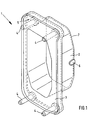
- FIGS. 1, 2 and 3 show an adapter 1 which is connected to a Front side of a motor carrier, not shown, is attachable. It consists of a flange 2, with which it can be inserted into the engine mount, and a thereof laterally projecting collar 3. The outer edge of the collar 3 is angled backwards. Distributed circumferentially around the collar 3 are four punched bolts 4 appropriate. The punching pins 4 are used together with the contact surface 5 of the Collar 3 for fixing a front end module not shown here. Of the Flange 2 has at one point a protruding outwardly to the engine mount nose. 6 on, with the adapter 1 in a corresponding recess in the engine mount can be fixed.
- the nose 6 is designed so that the adapter 1 in a defined Position is held after it is in the engine mount during its assembly was inserted. This prefixing allows the adapter 1 until the shell eintician the vehicle if the shell structure has arisen so far that the entire dimensional chain is fixed. So tolerances of the shell can be good be balanced before the adapter 1 is welded.
- the adapter 1 is a sheet metal forming part, which was formed from a high-strength, galvanized steel plate with a yield strength of 260 N / mm 2 .
- the wall thickness of the flange 2 decreases selectively over a step to the free end portion 7 down, so that there is only a wall thickness of 2.0 mm.
- This thin wall thickness makes it possible to weld the adapter 1 in this area with the motor carrier in the spot welding process, the welds can be spaced only about 30 mm apart. In this case, two circumferential rows of welds are set, which are offset from each other.
- the flange has a width of about 40 mm, so that the two rows of welding points have the required space.
- the wall thickness of the flange 2 increases to about 3 mm.
- the rounded transition region between flange 2 and collar 3 has a Wall thickness of 3 mm, or even slightly more. This is when forming tries to cause an accumulation of material in the transition area. This is the wall thickness in the particularly highly stressed areas relatively large.
- the angled back edge of the collar 3 serves to stiffen the Adapters 1. For the same reason, the angled edge of the collar 3 is also arranged as close to the punching pin 4. The high rigidity is both necessary for a crash as well as for towing.
Landscapes
- Engineering & Computer Science (AREA)
- Mechanical Engineering (AREA)
- Body Structure For Vehicles (AREA)
Description
- Fig. 1
- eine perspektivische Ansicht eines Adapters,
- Fig. 2
- eine Draufsicht auf den Adapter von Fig. 1 und
- Fig. 3
- eine Seitenansicht des Adapters von Fig. 1.
Claims (16)
- Stirnseitig an einem Motorträger anbringbarer Adapter (1), an dem ein Frontend oder Stoßfänger anbringbar ist, wobei der Adapter (1) ein Blechumformteil ist und einen Flansch (2) aufweist, mit dem der Adapter (1) formschlüssig über den Motorträger schiebbar oder in den Motorträger einlegbar ist, dadurch gekennzeichnet, dass der Flansch (2) an einer Stelle eine nach außen zum Motorträger ragende Nase (6) aufweist, mit der der Adapter (1) in einer entsprechenden Ausnehmung im Motorträger haltbar ist und dass der Adapter (1) an den Motorträger punkt verschweißbar ist.
- Stirnseitig an einem Motorträger anbringbarer Adapter (1), an dem ein Frontend oder Stoßfänger anbringbar ist, wobei der Adapter (1) ein Blechumformteil ist und einen Flansch (2) aufweist, mit dem der Adapter (1) formschlüssig über den Motorträger schiebbar oder in den Motorträger einlegbar ist, dadurch gekennzeichnet, dass die Wandstärke des Flanschs (2) zum freien Ende (7) hin abnimmt und dass der Adapter (1) an der Motorträger punkt verschweißbar ist.
- Adapter nach Anspruch 2, dadurch gekennzeichnet, dass der Flansch (2) am freien Ende (7) nur mehr etwa eine Wandstärke von 2,5 mm oder weniger aufweist.
- Adapter nach einem der vorhergehenden Ansprüche, dadurch gekennzeichnet, dass der Flansch (2) eine Breite von mindestens 30 mm hat.
- Adapter nach Anspruch 4, dadurch gekennzeichnet, dass der Flansch (2) eine Breite von mindestens 40 mm hat.
- Adapter nach einem der vorhergehenden Ansprüche, dadurch gekennzeichnet, dass das freie Ende (7) des Flanschs (2) mit dem Motorträger durch Punktschweißen verbunden ist.
- Adapter nach Anspruch 6, dadurch gekennzeichnet, dass das freie Ende des Flanschs (2) mit zwei umlaufenden Reihen von Schweißpunkten mit dem Motorträger verbunden ist.
- Adapter nach Anspruch 6 oder 7, dadurch gekennzeichnet, dass die Schweißpunkte mit einem Abstand von weniger als 30 mm untereinander gesetzt sind.
- Adapter nach einem der vorhergehenden Ansprüche, dadurch gekennzeichnet, dass der Adapter (1) einen Kragen (3) zur Anbringung des Frontends oder Stoßfängers aufweist.
- Adapter nach Anspruch 9, dadurch gekennzeichnet, dass der Kragen (3) sich in einer Ebene etwa senkrecht zur Fahrzeuglängsrichtung erstreckt.
- Adapter nach Anspruch 9 oder 10, dadurch gekennzeichnet, dass der äußere Rand des Kragens (3) abgewinkelt ist.
- Adapter nach einem der Ansprüche 9 bis 11, dadurch gekennzeichnet, dass an dem Kragen (3) Befestigungsbolzen (4) angebracht sind.
- Adapter nach einem der Ansprüche 9 bis 12, dadurch gekennzeichnet, dass der Kragen (3) Durchzüge mit eingepressten Gewinden aufweist.
- Adapter nach einem der Ansprüche 9 bis 13, dadurch gekennzeichnet, dass der Übergang zwischen Flansch (2) und Kragen (3) mit einem Radius abgerundet ist.
- Adapter nach einem der vorhergehenden Ansprüche, dadurch gekennzeichnet, dass das Stahlblech vor dem Umformen eine Streckgrenze von mindestens 220 N / mm2 hat.
- Adapter nach Anspruch 15, dadurch gekennzeichnet, dass der Adapter (1) in den in hohem Maße umgeformten Bereichen eine Streckgrenze von über 400 N / mm2 aufweist.
Applications Claiming Priority (2)
| Application Number | Priority Date | Filing Date | Title |
|---|---|---|---|
| DE10253101 | 2002-11-13 | ||
| DE2002153101 DE10253101A1 (de) | 2002-11-13 | 2002-11-13 | Stirnseitig an einem Motorträger anbringbarer Adapter |
Publications (2)
| Publication Number | Publication Date |
|---|---|
| EP1419937A1 EP1419937A1 (de) | 2004-05-19 |
| EP1419937B1 true EP1419937B1 (de) | 2005-10-26 |
Family
ID=32115514
Family Applications (1)
| Application Number | Title | Priority Date | Filing Date |
|---|---|---|---|
| EP20030025639 Expired - Lifetime EP1419937B1 (de) | 2002-11-13 | 2003-11-05 | Stirnseitig an einem Motorträger anbringbarer Adapter |
Country Status (3)
| Country | Link |
|---|---|
| EP (1) | EP1419937B1 (de) |
| DE (2) | DE10253101A1 (de) |
| ES (1) | ES2249674T3 (de) |
Cited By (1)
| Publication number | Priority date | Publication date | Assignee | Title |
|---|---|---|---|---|
| FR3167109A1 (fr) * | 2024-10-03 | 2026-04-10 | Stellantis Auto Sas | Vehicule automobile comportant une piece de renfort pour le remorquage |
Family Cites Families (7)
| Publication number | Priority date | Publication date | Assignee | Title |
|---|---|---|---|---|
| GB261213A (en) * | 1926-01-05 | 1926-11-18 | Joseph Edge Beckett | Improvements in or relating to buffer-bars for motor vehicles |
| DE2625724A1 (de) * | 1976-06-09 | 1977-12-22 | Audi Nsu Auto Union Ag | Selbsttragende karosserie mit zwei durch quertraeger verbundenen laengstraegern fuer kraftfahrzeuge |
| JPS57194135A (en) * | 1981-05-26 | 1982-11-29 | Nissan Motor Co Ltd | Bumper supporting structure for car |
| JPS61196848A (ja) * | 1985-02-27 | 1986-09-01 | Nissan Motor Co Ltd | 自動車用リヤバンパ取付装置 |
| US5080410A (en) * | 1991-04-22 | 1992-01-14 | Chrysler Corporation | Vehicle bumper beam |
| DE19958996A1 (de) * | 1999-12-08 | 2001-06-13 | Daimler Chrysler Ag | Querträgermodul für einen front- oder heckseitigen Stirnbereich eines Kraftfahrzeugs |
| JP3968685B2 (ja) * | 2000-06-02 | 2007-08-29 | スズキ株式会社 | バンパメンバ取付構造 |
-
2002
- 2002-11-13 DE DE2002153101 patent/DE10253101A1/de not_active Withdrawn
-
2003
- 2003-11-05 ES ES03025639T patent/ES2249674T3/es not_active Expired - Lifetime
- 2003-11-05 DE DE50301475T patent/DE50301475D1/de not_active Expired - Lifetime
- 2003-11-05 EP EP20030025639 patent/EP1419937B1/de not_active Expired - Lifetime
Cited By (1)
| Publication number | Priority date | Publication date | Assignee | Title |
|---|---|---|---|---|
| FR3167109A1 (fr) * | 2024-10-03 | 2026-04-10 | Stellantis Auto Sas | Vehicule automobile comportant une piece de renfort pour le remorquage |
Also Published As
| Publication number | Publication date |
|---|---|
| ES2249674T3 (es) | 2006-04-01 |
| DE10253101A1 (de) | 2004-05-27 |
| DE50301475D1 (de) | 2005-12-01 |
| EP1419937A1 (de) | 2004-05-19 |
Similar Documents
| Publication | Publication Date | Title |
|---|---|---|
| EP0664753B1 (de) | Endseitiger abschluss eines fahrzeuglängsträgers | |
| DE102016015020B4 (de) | Vordere Fahrzeugkarosseriestruktur und Verfahren zum Erhöhen der Festigkeit derselben | |
| DE102013005603B4 (de) | Fahrzeugkarosserie-Frontstruktur eines Fahrzeugs | |
| DE10007790B4 (de) | Anordnung zum Anbringen eines Hilfsrahmens an einer Fahrzeugkarosserie | |
| DE69014045T2 (de) | Stossfänger für Kraftfahrzeuge. | |
| DE60015195T2 (de) | Verfahren zur Herstellung eines Abgasrohres mit einer Doppelleitungsanordnung und Abgasrohr mit einer Doppelleitungsanordnung | |
| DE10041063B4 (de) | Verbindungsstruktur für extrudierte Elemente | |
| DE102016121254B4 (de) | Batterieträger mit Toleranzausgleichselement | |
| DE10151211B4 (de) | Fahrzeug-Karosseriestruktur | |
| DE102016015016A1 (de) | Vordere Fahrzeugkarosseriestruktur und Verfahren zum Erhöhen der Festigkeit derselben | |
| EP1912850B1 (de) | Kraftfahrzeugkarosserie mit einer federbeinaufnahme | |
| EP3838722B1 (de) | Hilfsrahmen für ein kraftfahrzeug | |
| DE19812084B4 (de) | Bodenaufbau eines Fahrzeugs | |
| DE69902550T2 (de) | Langgestreckte tragstruktur mit hohlprofilträger mit einem querflansch an beiden endflächen | |
| EP1880784A2 (de) | Verbund aus einem Leichtmetallgussbauteil und einem Stahlbauteil | |
| DE19603954C2 (de) | Prallträger für ein Kraftfahrzeug | |
| EP3022086B1 (de) | Rückenlehnenstruktur für einen fahrzeugsitz und fahrzeugsitz | |
| DE112006000143B4 (de) | Instrumentenbrettquerträger | |
| DE202007018727U1 (de) | Abschleppbuchseneinheit | |
| DE102011016055A1 (de) | Vorrichtung, insbesondere am Vorder- und Hinterwagen eines Kraftfahrzeugs | |
| DE102017200113B4 (de) | Stoßfängerquerträger für ein Kraftfahrzeug sowie Kraftfahrzeug mit einem solchen Stoßfängerquerträger | |
| DE10357172B4 (de) | Hilfsrahmenmontagestruktur eines Fahrzeuges | |
| EP0673829A2 (de) | Träger für die Lenksäule eines Kraftfahrzeuges | |
| DE102018120872A1 (de) | Deflektorschiene für Rahmenlängsträger | |
| DE102016206649A1 (de) | Hilfsrahmen für ein Fahrzeug |
Legal Events
| Date | Code | Title | Description |
|---|---|---|---|
| PUAI | Public reference made under article 153(3) epc to a published international application that has entered the european phase |
Free format text: ORIGINAL CODE: 0009012 |
|
| AK | Designated contracting states |
Kind code of ref document: A1 Designated state(s): AT BE BG CH CY CZ DE DK EE ES FI FR GB GR HU IE IT LI LU MC NL PT RO SE SI SK TR |
|
| AX | Request for extension of the european patent |
Extension state: AL LT LV MK |
|
| 17P | Request for examination filed |
Effective date: 20041104 |
|
| AKX | Designation fees paid |
Designated state(s): CZ DE ES FR GB IT |
|
| 17Q | First examination report despatched |
Effective date: 20050118 |
|
| GRAP | Despatch of communication of intention to grant a patent |
Free format text: ORIGINAL CODE: EPIDOSNIGR1 |
|
| GRAS | Grant fee paid |
Free format text: ORIGINAL CODE: EPIDOSNIGR3 |
|
| GRAA | (expected) grant |
Free format text: ORIGINAL CODE: 0009210 |
|
| AK | Designated contracting states |
Kind code of ref document: B1 Designated state(s): CZ DE ES FR GB IT |
|
| REG | Reference to a national code |
Ref country code: GB Ref legal event code: FG4D Free format text: NOT ENGLISH |
|
| GBT | Gb: translation of ep patent filed (gb section 77(6)(a)/1977) |
Effective date: 20051026 |
|
| REF | Corresponds to: |
Ref document number: 50301475 Country of ref document: DE Date of ref document: 20051201 Kind code of ref document: P |
|
| REG | Reference to a national code |
Ref country code: ES Ref legal event code: FG2A Ref document number: 2249674 Country of ref document: ES Kind code of ref document: T3 |
|
| ET | Fr: translation filed | ||
| PLBE | No opposition filed within time limit |
Free format text: ORIGINAL CODE: 0009261 |
|
| STAA | Information on the status of an ep patent application or granted ep patent |
Free format text: STATUS: NO OPPOSITION FILED WITHIN TIME LIMIT |
|
| 26N | No opposition filed |
Effective date: 20060727 |
|
| REG | Reference to a national code |
Ref country code: FR Ref legal event code: PLFP Year of fee payment: 13 |
|
| REG | Reference to a national code |
Ref country code: FR Ref legal event code: PLFP Year of fee payment: 14 |
|
| REG | Reference to a national code |
Ref country code: FR Ref legal event code: PLFP Year of fee payment: 15 |
|
| PGFP | Annual fee paid to national office [announced via postgrant information from national office to epo] |
Ref country code: CZ Payment date: 20191023 Year of fee payment: 17 Ref country code: DE Payment date: 20191112 Year of fee payment: 17 |
|
| PGFP | Annual fee paid to national office [announced via postgrant information from national office to epo] |
Ref country code: ES Payment date: 20191216 Year of fee payment: 17 Ref country code: FR Payment date: 20191121 Year of fee payment: 17 Ref country code: IT Payment date: 20191120 Year of fee payment: 17 |
|
| PGFP | Annual fee paid to national office [announced via postgrant information from national office to epo] |
Ref country code: GB Payment date: 20191126 Year of fee payment: 17 |
|
| REG | Reference to a national code |
Ref country code: DE Ref legal event code: R119 Ref document number: 50301475 Country of ref document: DE |
|
| GBPC | Gb: european patent ceased through non-payment of renewal fee |
Effective date: 20201105 |
|
| PG25 | Lapsed in a contracting state [announced via postgrant information from national office to epo] |
Ref country code: CZ Free format text: LAPSE BECAUSE OF NON-PAYMENT OF DUE FEES Effective date: 20201105 |
|
| PG25 | Lapsed in a contracting state [announced via postgrant information from national office to epo] |
Ref country code: IT Free format text: LAPSE BECAUSE OF NON-PAYMENT OF DUE FEES Effective date: 20201105 Ref country code: FR Free format text: LAPSE BECAUSE OF NON-PAYMENT OF DUE FEES Effective date: 20201130 |
|
| PG25 | Lapsed in a contracting state [announced via postgrant information from national office to epo] |
Ref country code: GB Free format text: LAPSE BECAUSE OF NON-PAYMENT OF DUE FEES Effective date: 20201105 Ref country code: DE Free format text: LAPSE BECAUSE OF NON-PAYMENT OF DUE FEES Effective date: 20210601 |
|
| REG | Reference to a national code |
Ref country code: ES Ref legal event code: FD2A Effective date: 20220131 |
|
| PG25 | Lapsed in a contracting state [announced via postgrant information from national office to epo] |
Ref country code: ES Free format text: LAPSE BECAUSE OF NON-PAYMENT OF DUE FEES Effective date: 20201106 |
|
| P01 | Opt-out of the competence of the unified patent court (upc) registered |
Free format text: CASE NUMBER: UPC_APP_327447/2023 Effective date: 20230523 |