EP1419539B1 - Monolithischer vielschichtaktor in einem gehäuse - Google Patents
Monolithischer vielschichtaktor in einem gehäuse Download PDFInfo
- Publication number
- EP1419539B1 EP1419539B1 EP02751087A EP02751087A EP1419539B1 EP 1419539 B1 EP1419539 B1 EP 1419539B1 EP 02751087 A EP02751087 A EP 02751087A EP 02751087 A EP02751087 A EP 02751087A EP 1419539 B1 EP1419539 B1 EP 1419539B1
- Authority
- EP
- European Patent Office
- Prior art keywords
- housing
- actuator
- water
- medium
- multilayer actuator
- Prior art date
- Legal status (The legal status is an assumption and is not a legal conclusion. Google has not performed a legal analysis and makes no representation as to the accuracy of the status listed.)
- Expired - Lifetime
Links
- 239000000919 ceramic Substances 0.000 claims abstract description 14
- 239000010409 thin film Substances 0.000 claims abstract description 3
- 229910052751 metal Inorganic materials 0.000 claims description 12
- 239000002184 metal Substances 0.000 claims description 12
- 238000000034 method Methods 0.000 claims description 12
- 239000010408 film Substances 0.000 claims description 10
- KWGKDLIKAYFUFQ-UHFFFAOYSA-M lithium chloride Chemical compound [Li+].[Cl-] KWGKDLIKAYFUFQ-UHFFFAOYSA-M 0.000 claims description 6
- 229920002545 silicone oil Polymers 0.000 claims description 5
- BRPQOXSCLDDYGP-UHFFFAOYSA-N calcium oxide Chemical compound [O-2].[Ca+2] BRPQOXSCLDDYGP-UHFFFAOYSA-N 0.000 claims description 4
- 239000000292 calcium oxide Substances 0.000 claims description 4
- ODINCKMPIJJUCX-UHFFFAOYSA-N calcium oxide Inorganic materials [Ca]=O ODINCKMPIJJUCX-UHFFFAOYSA-N 0.000 claims description 4
- UXVMQQNJUSDDNG-UHFFFAOYSA-L Calcium chloride Chemical compound [Cl-].[Cl-].[Ca+2] UXVMQQNJUSDDNG-UHFFFAOYSA-L 0.000 claims description 3
- 239000004721 Polyphenylene oxide Substances 0.000 claims description 3
- 239000001110 calcium chloride Substances 0.000 claims description 3
- 229910001628 calcium chloride Inorganic materials 0.000 claims description 3
- 150000001722 carbon compounds Chemical class 0.000 claims description 3
- 239000007788 liquid Substances 0.000 claims description 3
- 239000002808 molecular sieve Substances 0.000 claims description 3
- 229920000570 polyether Polymers 0.000 claims description 3
- 238000007789 sealing Methods 0.000 claims description 3
- URGAHOPLAPQHLN-UHFFFAOYSA-N sodium aluminosilicate Chemical compound [Na+].[Al+3].[O-][Si]([O-])=O.[O-][Si]([O-])=O URGAHOPLAPQHLN-UHFFFAOYSA-N 0.000 claims description 3
- 239000000126 substance Substances 0.000 claims description 3
- -1 silicate compound Chemical class 0.000 claims description 2
- 229910010293 ceramic material Inorganic materials 0.000 claims 1
- 239000000470 constituent Substances 0.000 claims 1
- 239000000463 material Substances 0.000 claims 1
- 239000000843 powder Substances 0.000 description 12
- 239000004020 conductor Substances 0.000 description 11
- XLYOFNOQVPJJNP-UHFFFAOYSA-N water Chemical compound O XLYOFNOQVPJJNP-UHFFFAOYSA-N 0.000 description 10
- 238000007650 screen-printing Methods 0.000 description 9
- KDLHZDBZIXYQEI-UHFFFAOYSA-N Palladium Chemical compound [Pd] KDLHZDBZIXYQEI-UHFFFAOYSA-N 0.000 description 8
- 239000002274 desiccant Substances 0.000 description 5
- 238000010586 diagram Methods 0.000 description 5
- 229920006335 epoxy glue Polymers 0.000 description 5
- 229910052709 silver Inorganic materials 0.000 description 5
- 239000004332 silver Substances 0.000 description 5
- 239000011248 coating agent Substances 0.000 description 4
- 238000000576 coating method Methods 0.000 description 4
- 238000005538 encapsulation Methods 0.000 description 4
- 229920006332 epoxy adhesive Polymers 0.000 description 4
- 229910052574 oxide ceramic Inorganic materials 0.000 description 4
- 239000011224 oxide ceramic Substances 0.000 description 4
- TWNQGVIAIRXVLR-UHFFFAOYSA-N oxo(oxoalumanyloxy)alumane Chemical compound O=[Al]O[Al]=O TWNQGVIAIRXVLR-UHFFFAOYSA-N 0.000 description 4
- 229910052763 palladium Inorganic materials 0.000 description 4
- 239000011149 active material Substances 0.000 description 3
- 150000001875 compounds Chemical class 0.000 description 3
- 230000005684 electric field Effects 0.000 description 3
- 238000011049 filling Methods 0.000 description 3
- 239000000499 gel Substances 0.000 description 3
- 238000000227 grinding Methods 0.000 description 3
- 238000001465 metallisation Methods 0.000 description 3
- 229920001296 polysiloxane Polymers 0.000 description 3
- 239000004590 silicone sealant Substances 0.000 description 3
- 238000005245 sintering Methods 0.000 description 3
- 238000005476 soldering Methods 0.000 description 3
- RYGMFSIKBFXOCR-UHFFFAOYSA-N Copper Chemical compound [Cu] RYGMFSIKBFXOCR-UHFFFAOYSA-N 0.000 description 2
- BPQQTUXANYXVAA-UHFFFAOYSA-N Orthosilicate Chemical compound [O-][Si]([O-])([O-])[O-] BPQQTUXANYXVAA-UHFFFAOYSA-N 0.000 description 2
- 239000000853 adhesive Substances 0.000 description 2
- 230000001070 adhesive effect Effects 0.000 description 2
- 229910052782 aluminium Inorganic materials 0.000 description 2
- XAGFODPZIPBFFR-UHFFFAOYSA-N aluminium Chemical compound [Al] XAGFODPZIPBFFR-UHFFFAOYSA-N 0.000 description 2
- 239000011230 binding agent Substances 0.000 description 2
- 238000009835 boiling Methods 0.000 description 2
- 238000005266 casting Methods 0.000 description 2
- 238000001816 cooling Methods 0.000 description 2
- 239000011889 copper foil Substances 0.000 description 2
- 238000005520 cutting process Methods 0.000 description 2
- 239000011521 glass Substances 0.000 description 2
- 229910052451 lead zirconate titanate Inorganic materials 0.000 description 2
- 238000004519 manufacturing process Methods 0.000 description 2
- 239000002245 particle Substances 0.000 description 2
- 238000004382 potting Methods 0.000 description 2
- 239000002966 varnish Substances 0.000 description 2
- PNEYBMLMFCGWSK-UHFFFAOYSA-N Alumina Chemical compound [O-2].[O-2].[O-2].[Al+3].[Al+3] PNEYBMLMFCGWSK-UHFFFAOYSA-N 0.000 description 1
- VYPSYNLAJGMNEJ-UHFFFAOYSA-N Silicium dioxide Chemical compound O=[Si]=O VYPSYNLAJGMNEJ-UHFFFAOYSA-N 0.000 description 1
- 238000004026 adhesive bonding Methods 0.000 description 1
- 239000000956 alloy Substances 0.000 description 1
- 229910045601 alloy Inorganic materials 0.000 description 1
- 238000013459 approach Methods 0.000 description 1
- 238000005524 ceramic coating Methods 0.000 description 1
- 239000013078 crystal Substances 0.000 description 1
- 238000013461 design Methods 0.000 description 1
- 238000003795 desorption Methods 0.000 description 1
- 229910003460 diamond Inorganic materials 0.000 description 1
- 239000010432 diamond Substances 0.000 description 1
- 238000001035 drying Methods 0.000 description 1
- 230000000694 effects Effects 0.000 description 1
- 238000010292 electrical insulation Methods 0.000 description 1
- 239000002003 electrode paste Substances 0.000 description 1
- 238000009713 electroplating Methods 0.000 description 1
- 230000002349 favourable effect Effects 0.000 description 1
- 239000011888 foil Substances 0.000 description 1
- 238000010438 heat treatment Methods 0.000 description 1
- HFGPZNIAWCZYJU-UHFFFAOYSA-N lead zirconate titanate Chemical compound [O-2].[O-2].[O-2].[O-2].[O-2].[Ti+4].[Zr+4].[Pb+2] HFGPZNIAWCZYJU-UHFFFAOYSA-N 0.000 description 1
- 239000007791 liquid phase Substances 0.000 description 1
- 238000005259 measurement Methods 0.000 description 1
- 238000013208 measuring procedure Methods 0.000 description 1
- 239000007769 metal material Substances 0.000 description 1
- 239000002480 mineral oil Substances 0.000 description 1
- 238000002156 mixing Methods 0.000 description 1
- 229910000510 noble metal Inorganic materials 0.000 description 1
- 239000003973 paint Substances 0.000 description 1
- 239000010702 perfluoropolyether Substances 0.000 description 1
- 230000035699 permeability Effects 0.000 description 1
- 239000012466 permeate Substances 0.000 description 1
- 239000004014 plasticizer Substances 0.000 description 1
- 230000010287 polarization Effects 0.000 description 1
- 238000002360 preparation method Methods 0.000 description 1
- 238000007639 printing Methods 0.000 description 1
- 230000002787 reinforcement Effects 0.000 description 1
- 238000007493 shaping process Methods 0.000 description 1
- 238000007873 sieving Methods 0.000 description 1
- 239000000741 silica gel Substances 0.000 description 1
- 229910002027 silica gel Inorganic materials 0.000 description 1
- 239000004447 silicone coating Substances 0.000 description 1
- 239000002904 solvent Substances 0.000 description 1
- 238000001179 sorption measurement Methods 0.000 description 1
- 238000003466 welding Methods 0.000 description 1
Images


Classifications
-
- H—ELECTRICITY
- H10—SEMICONDUCTOR DEVICES; ELECTRIC SOLID-STATE DEVICES NOT OTHERWISE PROVIDED FOR
- H10N—ELECTRIC SOLID-STATE DEVICES NOT OTHERWISE PROVIDED FOR
- H10N30/00—Piezoelectric or electrostrictive devices
- H10N30/80—Constructional details
- H10N30/88—Mounts; Supports; Enclosures; Casings
- H10N30/883—Additional insulation means preventing electrical, physical or chemical damage, e.g. protective coatings
-
- H—ELECTRICITY
- H10—SEMICONDUCTOR DEVICES; ELECTRIC SOLID-STATE DEVICES NOT OTHERWISE PROVIDED FOR
- H10N—ELECTRIC SOLID-STATE DEVICES NOT OTHERWISE PROVIDED FOR
- H10N30/00—Piezoelectric or electrostrictive devices
- H10N30/80—Constructional details
- H10N30/88—Mounts; Supports; Enclosures; Casings
-
- H—ELECTRICITY
- H10—SEMICONDUCTOR DEVICES; ELECTRIC SOLID-STATE DEVICES NOT OTHERWISE PROVIDED FOR
- H10N—ELECTRIC SOLID-STATE DEVICES NOT OTHERWISE PROVIDED FOR
- H10N30/00—Piezoelectric or electrostrictive devices
- H10N30/50—Piezoelectric or electrostrictive devices having a stacked or multilayer structure
Definitions
- the invention relates to a monolithic multilayer actuator according to the preamble of claim 1.
- Piezoceramic multilayer actuators consist of stacked thin layers of piezoelectric active material 2, z.
- PZT lead zirconate titanate
- External electrodes. 3, 4 connect these internal electrodes.
- the internal electrodes are electrically connected in parallel and combined into two groups, which represent the two terminal poles of the actuator. Applying an electrical voltage to the terminal poles, this is transferred to all internal electrodes in parallel and causes an electric field in all layers of active material, thereby mechanically deformed. The sum of all these mechanical deformations is available at the end faces of the actuator as usable strain 6 and / or force. Via electrical connecting wires 5, the terminal poles are driven.
- Piezoceramic multilayer actuators are designed according to the prior art as monoliths, i. H. the active material is provided before sintering as a so-called green sheet by means of a screen printing by means of noble metal paste with internal electrodes, pressed into actuator stacks, pyrolysed and then sintered, whereby the monolithic actuator is formed.
- actuators require that the component be subjected to the rated voltage for a long period of time without changing its properties.
- Typical applications are positioning and positioning drives, which approach a certain position and may have to last for months and years. This requirement can not be met with actuators according to the above-described prior art.
- the reason for this is that the high electric field strength at the actuator surface attracts polar molecules, usually water vapor, from the environment. This water vapor permeates all known polymeric sheaths more or less quickly and finally leads to increased conductivity at the actuator surface and increasing leakage current.
- the leakage current increases until an equilibrium for water vapor adsorption by the electric field and desorption by the actuator temperature sets by the likewise increasing actuator temperature.
- the water vapor penetrates through microcracks of the coating, which inevitably form as a result of the operation of the actuator.
- the generic JP 04-349675 A with associated abstract shows a monolithic multilayer actuator of a sintered stack of thin films of piezoceramic with embedded metallic internal electrodes that lead mutually out of the stack and are electrically connected in parallel via external electrodes and are provided with connecting wires, the multilayer actuator of a housing with a housing shell, a housing cover and a housing bottom is sealingly enclosed and the housing is filled with a water-absorbing medium.
- EP 0 319 038 A2 and WO 99/303 74 A1 also show a monolithic multilayer actuator, however, the problem that even the smallest leaks resulting from ingress of moisture lead to a change in the properties of the actuator is not discussed.
- the invention has for its object to improve a multilayer actuator according to the preamble of claim 1 so that the actuators can be applied over long periods of the nominal voltage without this changes its properties.
- this object is solved by the features of claim 1.
- the multilayer actuator of a metallic or ceramic housing is sealingly enclosed, wherein the connecting wires are integral components of the housing bottom and the housing is filled with a water-absorbing medium and a water-transporting, electrically insulating medium.
- Such encapsulated actuators show consistently low leakage currents, even if they are permanently operated with the nominal field strength.
- Diagram 2 shows the leakage current profile on such an encapsulated actuator. Actuator dimensions and other parameters correspond to the measurement in Diagram 1. The leakage current of the encapsulated component is about 1000 times smaller than that of the non-encapsulated component Actuator. A ceramic housing, silicate desiccant and a perfluoropolyether filling were used.
- the housing consists of a housing jacket, in particular a tubular housing jacket, with a housing cover and a housing bottom, wherein the housing cover is placed on the housing jacket with a permanently elastic sealing medium.
- the caseback is made of ceramic.
- the connecting wires are applied in the form of printed conductors on the housing bottom.
- the printed conductors are preferably produced by the thick-film process (printing of metal paste and baking into the housing bottom).
- the water-transporting, electrically insulating medium is a liquid and originates in particular from the classes of silicone oils or perfluorinated carbon compounds. Preference is given to the water-transporting, electrically insulating medium perfluorinated polyether.
- the water-absorbing medium is a silicate compound, anhydrous calcium oxide or a hygroscopic substance such as calcium chloride or lithium chloride and consists in particular of dry gel or a molecular sieve.
- a low sintering piezoceramic, z. B. SKN53 to DE 198 40 488 A1 is prepared with an organic binder system as a 125 micron thick film. On this film, a commercially available internal electrode paste is applied by screen printing. A plurality of such films are stacked and pressed into a laminate, wherein some films remain on the top and / or bottom of the laminate without internal electrodes to produce an inactive region, at which the actuator can later be electrically contacted. The laminate is cut into individual, rod-shaped actuators, these are sintered at 900 ° C - 1100 ° C, preferably at 1000 ° C.
- the base metallization 33 of silver is applied to the contact sides by means of a screen printing / baking process.
- the outer electrodes of metal wire mesh are soldered to it.
- the actuators are now insulated with a commercially available silicone varnish. Silicone has the highest permeability to water vapor of all known paint types. The actuators can now be polarized and measured electrically.
- An actuator housing is made by cutting a metal tube or ceramic tube as the housing jacket 8 so that it is about 0.5 mm shorter than the actuator 1.
- the inner diameter of the tube piece is such that the actuator 1 does not touch the tube wall when in the pipe is inserted. If a metal tube is used, it must receive two recesses 10 at the points at which the tracks 13 of the bottom part 11 perform under the tube 8.
- a bottom part 11 for the housing is made by a two-lane paste 13 on a plane-parallel, but otherwise arbitrarily shaped ceramic plate with a thick film paste by screen printing and baking.
- B. are printed and baked from a silver-Pälladium alloy, which make contact with the actuator 1 and which protrude below the ceramic or metal tube 8.
- the actuator 1 will now be e.g. glued with an epoxy adhesive on the bottom part, that it can be contacted by the two interconnects 13.
- the contact is made by soldering, welding or gluing with conductive adhesive. L-shaped metal contact strips facilitate this process.
- the actuator housing or the housing shell 8 is inserted over the actuator 1, and with the bottom part 11 z. B. glued with an epoxy adhesive.
- Actuator 1 is now about 0.5 mm above the housing. He must not touch the case during this process.
- the space between actuator and actuator housing is now filled with water-absorbing, powdered medium 14, such as crushed dry gel.
- powdered medium 14 such as crushed dry gel.
- the dry powder is dewatered before filling at elevated temperature.
- this procedure depends on the type of desiccant used. There are in principle all water-attracting substances such. Calcium oxide, calcium chloride, lithium chloride and the like. However, the latter, if they have taken up too much water, form a liquid phase which can lead to flashovers on the surface of the actuator.
- Desiccant on a silicate basis such as. As silica gel and perovskite molecular sieves, bind the water in the crystal structure. When the desiccant is exhausted, the leakage current slowly increases. It does not come to the failure of the component.
- the powder bed is now soaked with liquid, but water-conducting insulating medium 15.
- This insulating medium must be filled before filling e.g. be made anhydrous by heating.
- silicone oils and perfluorinated carbon compounds are suitable. Silicone casting compounds and mineral oils are slower in their mode of action (water transport), but are in principle the same with careful, anhydrous work.
- the housing cover which consists of a plane-parallel ceramic plate, is e.g. glued to the actuator with an epoxy glue.
- the remaining joint 17 between the housing cover 16 and actuator housing 8 is z with a permanently elastic sealing medium.
- a 125 ⁇ m thick green film made of SKN53 is prepared by treating the ceramic powder ground to an average particle size of about 1 ⁇ m with solvents, organic binders, plasticizers and dispersing aids to give a casting slip, from which an endless foil is poured by means of the doctor-blade process and this dries.
- a réellemetallmaschinespaste containing as metal powder silver / palladium in a mixing ratio 70/30 is printed in the form of the desired internal electrode design by screen printing on the green sheet, the thickness of the print layer after drying is 8 microns.
- 360 printed films and 60 unprinted films are stacked together and pressed into a block at elevated temperature.
- the block is cut by means of a cutting tool made of hard metal to individual, rod-shaped actuators.
- the actuators are pyrolyzed at 400 ° C and then sintered at 1000 ° C for 10 h.
- the thickness of the inner electrodes is then about 3 microns. After sintering, the external dimensions of the actuators are 7.1 ⁇ 7.1 ⁇ 30.5 mm 3 .
- the actuators are now ground to size on all sides with diamond grinding wheels. After this process, the outer dimensions are 7 x 7 x 30 mm 3 .
- Silver / palladium 80/20 external electrodes are applied to the contact surfaces by screen printing and baked at 800 ° C.
- a net-like wire mesh (EP 0 844 678 A1) is soldered on for reinforcement.
- the actuators are now protected by a commercially available silicone coating varnish.
- the polarization then takes place by applying a voltage of 200 V to the components at a temperature of approx. 120 ° C.
- An alumina ceramic tube 8 having an inner diameter of 10 mm, an outer diameter of 12 mm and a length of 29.5 mm is produced.
- An aluminum oxide ceramic plate 11 (housing bottom) with the dimensions thickness 1 mm, length 15 mm, width 12 mm is prepared. The thickness is ground plane parallel.
- Two printed conductors 13 made of silver / palladium 80/20 are applied longitudinally next to one another by screen printing and baked at 800 ° C. The printed conductors 13 are 14 mm long, 5 mm wide and have a spacing of 1 mm.
- An aluminum oxide ceramic plate 16 (housing cover) with the dimensions diameter 12 mm, thickness 1 mm is produced. The thickness is ground plane parallel.
- Dry powder 14 is prepared by breaking down desiccant (blue gel) with a slab grinder and sieving to a particle size of 50 ⁇ m to 100 ⁇ m. The powder is dried in an oven at 120 ° C for about 10 hours anhydrous.
- Silicone oil as the insulating medium 15 is dried anhydrous at 120 ° C for about 10 hours.
- An actuator 1 is glued to the inactive foot 18 by means of epoxy adhesive on a bottom part, that, taking into account the entire housing diameter, the bottom part protrudes on one side.
- the outer electrodes 4 are soldered to the printed conductors 13 using copper foil strips.
- the ceramic tube 8 is guided over the actuator and glued to the bottom part 11 by means of epoxy adhesive.
- the bottom part is over on one side.
- the sub-housing with actuator is now baked at 120 ° C for 10 h.
- the gap between the actuator and the housing wall is filled with dry powder 14.
- the Dry powder is soaked with silicone oil 15.
- the cover part 16 is adhered centrally to the actuator by means of epoxy glue. During these steps, the temperature of the housing should never fall below 100 ° C.
- a connector printed circuit board connector
- Actuator encapsulated in this way have the following property when controlled with a DC voltage of 200 V:
- FIG. 4 The embodiment is shown in FIG. 4.
- Piezoelectric monolithic multilayer actuators are produced as in Ausfdhrungsbeispiel 1.
- An aluminum tube 8 having an inner diameter of 10 mm, an outer diameter of 10.5 mm and a length of 29.5 mm is produced.
- the tube receives two recesses 10 with the dimensions 0.5 mm high and 5 mm wide.
- An aluminum oxide ceramic plate 11 (housing bottom) with the dimensions thickness 1 mm, length 16.5 mm, width 10.5 mm is prepared. The thickness is ground plane parallel.
- On the tile are two consecutive longitudinal Printed conductors 13 made of silver / palladium 80/20 applied by screen printing and baked at 800 ° C. The printed conductors are 7.5 mm long, 4 mm wide and have a spacing of 1 mm.
- An aluminum oxide ceramic plate 16 (housing cover) with the dimensions diameter 12 mm, thickness 1 mm is produced. The thickness is ground plane parallel.
- ground anhydrous calcium oxide is used as dry powder 14.
- the chain length is adjusted so that a boiling temperature of 240 ° C results.
- the medium is heated to boiling temperature for several minutes to obtain anhydrous.
- An actuator is bonded to the inactive foot 18 by means of epoxy glue centrally on a bottom part, so that the outer electrodes 4 can be connected to the tracks of the bottom part.
- the outer electrodes 4 are soldered to the printed conductors 13 using copper foil strips.
- the aluminum tube 8 is guided over the actuator 1, so that the recesses lie over the conductor tracks 13 and glued to the bottom part 11 by means of epoxy glue.
- the bottom part is on both sides over.
- the recesses 10 are filled with the adhesive and are thus closed.
- the sub-housing with actuator is now baked at 120 ° C for 10 h.
- the gap between the actuator and the housing wall is filled with the dry powder 14.
- the dry powder 14 is impregnated with the insulating medium 15.
- the lid part 16 is adhesively bonded to the actuator by means of epoxy glue. During these steps, the temperature of the housing should never fall below 100 ° C.
- Actuators encapsulated in this way have the following properties when actuated with a DC voltage of 200 V:
Landscapes
- General Electrical Machinery Utilizing Piezoelectricity, Electrostriction Or Magnetostriction (AREA)
- Micromachines (AREA)
- Fuel-Injection Apparatus (AREA)
- Laminated Bodies (AREA)
Description
- Die Erfindung betrifft einen monolithischen Vielschichtaktor nach dem Oberbegriff des Anspruchs 1.
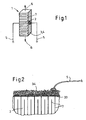
- Piezokeramische Vielschichtaktoren (PMA, siehe Figur 1) bestehen aus gestapelten dünnen Schichten piezoelektrisch aktiven Materials 2, z. B. Blei-Zirkonat-Titanat (PZT), mit dazwischen angeordneten leitfähigen Innenelektroden 7, die alternierend an die. Aktoroberfläche geführt werden. Außenelektroden. 3, 4 :verbinden diese Innenelektroden. Dadurch werden die Innenelektroden elektrisch parallel geschaltet und zu zwei Gruppen zusammengefasst, die die beiden Anschlusspole des Aktors darstellen. Legt man eine elektrische Spannung an die Anschlusspole, so wird diese auf alle Innen elektroden parallel übertragen und verursacht ein elektrisches Feld in allen Schichten aktiven Materials, das sich dadurch mechanisch verformt. Die Summe aller dieser mechanischen Verformungen steht an den Endflächen des Aktors als nutzbare Dehnung 6 und/oder Kraft zur Verfügung. Über elektrische Anschlussdrähte 5 werden die Anschlusspole angesteuert.
- Piezokeramische Vielschichtaktoren werden nach dem Stand der Technik als Monolithen ausgeführt, d. h. das aktive Material wird vor dem Sintern als sogenannte Grün-Folie durch ein Siebdruckverfahren mittels Edelmetallpaste mit Innenelektroden versehen, zu Aktorstapeln verpresst, pyrolysiert und dann gesintert, wodurch der monolithische Aktor entsteht.
- Die Oberflächen des Aktorkörpers werden nun durch ein formgebendes Verfahren, im allgemeinen durch Schleifen bearbeitet. Auf den Aktor 1 wird im Bereich der herausgeführten Innenelektroden 7, z. B. durch galvanische Verfahren oder Siebdruck von Metallpaste eine Grundmetallisierung 33 aufgebracht. Diese Grundmetallisierung wird verstärkt durch Aufbringen eines metallischen Werkstoffes 34, z. B. durch Anlöten eines strukturierten Bleches oder eines Drahtnetzes. An diese verstärkte Schicht wird der elektrische Anschlussdraht 5 gelötet. Vor oder nach dem Anlöten der Anschlussdrähte wird der Aktor mit einer elektrisch isolierenden Beschichtung überzogen, die zudem vor mechanischer Verletzung der Aktoroberflächen schützt.
- Figur 1 zeigt einen PMA allgemein, Figur 2 zeigt weitere Details.
- Der Aufbau und die Herstellung derartiger Aktoren und Außenelektroden wird ausführlich beschrieben z. B. in DE 33 30 538 A1, DE 40 36 287 C2, US 5 281 885, US 4 845 399, US 5 406 164 und JP 07-226541 A.
- Viele Anwendungen für Aktoren stellen die Forderung, dass das Bauteil über lange Zeiträume mit der Nennspannung beaufschlagt werden kann, ohne dass es seine Eigenschaften ändert. Typisch Anwendungen sind Stell- und Positionierantriebe, die eine bestimmte Position anfahren, und unter Umständen über Monate und Jahre halten müssen. Diese Anforderung kann mit Aktoren nach dem oben beschriebenen Stand der Technik nicht erfüllt werden.
- Ursache hierfür ist, dass durch die hohe elektrische Feldstärke an der Aktoroberfläche polare Moleküle, gewöhnlich Wasserdampf, aus der Umgebung angezogen werden. Dieser Wasserdampf durchdringt alle bekannten polymeren Umhüllungen mehr oder weniger schnell und führt schließlich an der Aktoroberfläche zu erhöhter Leitfähigkeit und zu ansteigendem Leckstrom. Der Leckstrom steigt solange an bis sich durch die ebenfalls ansteigende Aktortemperatur ein Gleichgewicht für Wasserdampfadsorption durch das elektrische Feld und Desorption durch die Aktortemperatur einstellt. Den typischen Leckstromverlauf über der Zeit für einen Aktor mit den Abmessungen 7 x 7 x 30 mm3 bei einer inneren Feldstärke von 2000 V/mm unter normalen Laborumgebungsbedingungen zeigt das Diagramm 1 bei 200 V, 25° C, 40 % rF.
- Verwendet man als Überzug keramische Beschichtungen oder Gläser, so dringt der Wasserdampf durch Mikrorisse der Beschichtung, die sich zwangsläufig durch den Betrieb des Aktors bilden.
- Auch das Umgießen mit einer geeigneten Vergussmasse in einem Metallgehäuse führt nicht zum Erfolg, da bereits die äußerst geringen Wassermengen, die in der Vergussmasse enthalten sind oder die während des Verkapselungsschrittes eindringen, genügen, den Effekt auszulösen.
- Einen weiteren Schwachpunkt bilden die Anschlussdrähte, die durch die Beschichtung, beziehungsweise das Gehäuse, nach außen geführt werden müssen. Durch Polymere geführte isolierte Drähte führen aus oben genannten Gründen nicht zum Ziel. Metall/Glas Durchführungen führen zu Problemen, weil sie durch die Bewegung des Aktors zerstört werden.
- Die gattungsbildende JP 04-349675 A mit zugehörigem Abstract zeigt einen monolithischen Vielschichtaktor aus einem gesinterten Stapel dünner Folien aus Piezokeramik mit eingelagerten metallischen Innenelektroden, die wechselseitig aus dem Stapel herausführen und über Außenelektroden elektrisch parallel geschaltet sind und mit Anschlussdrähten versehen sind, wobei der Vielschichtaktor von einem Gehäuse mit einem Gehäusemantel, einem Gehäusedeckel und einem Gehäuseboden dichtend umschlossen ist und das Gehäuse mit einem wasserabsorbierenden Medium gefüllt ist.
- EP 0 319 038 A2 und WO 99/303 74 A1 zeigen ebenfalls einen monolitischen Vielschichtaktor, jedoch wird auf die Problematik, dass auch kleinste Undichtigkeiten durch eindringende Feuchtigkeit zu einer Änderung der Eigenschaften des Aktors führen, nicht eingegangen.
- Der Erfindung liegt die Aufgabe zugrunde, einen Vielschichtaktor nach dem Oberbegriff des Anspruchs 1 so zu verbessern, dass die Aktoren über lange Zeiträume mit der Nennspannung beaufschlagt werden können, ohne dass dieser seine Eigenschaften ändert.
- Erfindungsgemäß wird diese Aufgabe durch die Merkmale des Anspruchs 1 gelöst. Erfindungsgemäß ist der Vielschichtaktor von einem metallischen oder keramischen Gehäuse dichtend umschlossen, wobei die Anschlussdrähte integrale Bestandteile des Gehäusebodens sind und das Gehäuse mit einem wasserabsorbierenden Medium und einem wassertransportierenden, elektrisch isolierenden Medium gefüllt ist.
- Derartig gekapselte Aktoren zeigen konstant niedrige Leckströme, auch wenn sie permanent mit der Nennfeldstärke betrieben werden. Diagramm 2 zeigt den Leckstromverlauf an einem derart gekapselten Aktor. Aktorabmessungen und sonstige Parameter entsprechen der Messung aus Diagramm 1. Der Leckstrom des gekapselten Bauteils ist etwa 1000 mal kleiner als der des ungekapselten Aktors. Verwendet wurde ein Keramikgehäuse, Silikat-Trockenmittel und eine Perfluorpolyäther-Füllung.
- Durch die eventuell vorhandene elastische Deckelfuge eindiffundierendes, oder bereits im Gehäuse vorhandenes Wasser, wird dadurch abgefangen und unschädlich gemacht.
- Erfindungsgemäß besteht das Gehäuse aus einem Gehäusemantel, insbesondere rohrförmigen Gehäusemantel, mit einem Gehäusedeckel und einem Gehäuseboden, wobei der Gehäusedeckel mit einem dauerelastischen Dichtmedium auf den Gehäusemantel aufgesetzt ist.
- Der Gehäuseboden besteht aus Keramik.
- Die Anschlussdrähte sind in Form von Leiterbahnen auf den Gehäuseboden aufgebracht.
- Bevorzugt werden die Leiterbahnen mit dem Dickschichtverfahren (Aufdrucken von Metallpaste und Einbrennen dieser in den Gehäuseboden) hergestellt.
- An die Anschlussdrähte bzw. die Leiterbahnen ist vorteilhafter Weise außerhalb des Gehäusemantels ein Steckverbinder angelötet.
- Erfindungsgemäß ist das wassertranspvrtierende, elektrisch isolierende Medium eine Flüssigkeit und stammt insbesondere aus den Klassen der Silikonöle oder der perfluorierten Kohlenstoffverbindungen. Bevorzugt ist das wassertransportierende, elektrisch isolierende Medium perfluorierter Polyäther.
- Das wasserabsorbierende Medium ist eine Silikatverbindung, wasserfreies Calciumoxid oder eine hygroskopische Substanz, wie Calciumchlorid oder Lithiumchlorid und besteht insbesondere aus Trockengel oder einem Molekularsieb.
- Nachfolgend wird die Herstellung des erfindungsgemäßen Vielschichtaktors im einzelnen beschrieben.
- Eine niedrig sinternde Piezokeramik, z. B. SKN53 nach DE 198 40 488 A1 wird mit einem organischen Bindersystem als 125 µm dicke Folie präpariert. Auf diese Folie wird eine handelsübliche Innenelektrodenpaste mittels Siebdruck aufgebracht. Eine Vielzahl derartiger Folien wird gestapelt und zu einem Laminat verpresst, wobei an Ober- und/oder Unterseite des Laminates einige Folien ohne Innenelektroden bleiben, um einen inaktiven Bereich zu erzeugen, an dem der Aktor später elektrisch kontaktiert werden kann. Das Laminat wird zu einzelnen, stabförmigen Aktoren zertrennt, diese werden bei 900°C - 1100 °C, vorzugsweise bei 1000 °C gesintert. Nach dem Schleifen der Aktoroberflächen wird die Grundmetallisierung 33 aus Silber mittels eines Siebdruck/Einbrennprozesses auf die Kontaktseiten aufgebracht. Die Außenelektroden aus Metalldraht-Netz werden darauf aufgelötet. Zum Schutz vor mechanischer Beschädigung und zur elektrischen Isolation bei den folgenden Messvorgängen werden die Aktoren nun mit einem handelsüblichen Silikonlack isoliert. Silikon hat von allen bekannten Lacktypen die höchste Durchlässigkeit für Wasserdampf. Die Aktoren können nun polarisiert und elektrisch gemessen werden.
- Ein Aktorgehäuse wird hergestellt, indem ein Metallrohr oder Keramikrohr als Gehäusemantel 8 abgelängt wird, so dass es etwa 0,5 mm kürzer ist als der Aktor 1. Der Innendurchmesser des Rohrstückes ist derart, dass der Aktor 1 die Rohrwandung nicht berührt, wenn er in das Rohr eingefügt wird. Wird ein Metallrohr verwendet, so muss es zwei Aussparungen 10 an den Stellen erhalten, an denen die Leiterbahnen 13 des Bodenteils 11 unter dem Rohr 8 durchführen.
- Ein Bodenteil 11 für das Gehäuse wird hergestellt, indem auf ein planparalleles, aber sonst beliebig geformtes Keramikplättchen mit einer Dickschichtpaste mittels Siebdruck und Einbrennen zwei Leiterbahnen 13 z. B. aus einer Silber-Pälladium Legierung aufgedruckt und eingebrannt werden, die den Kontakt zum Aktor 1 herstellen und die unter dem Keramik- oder Metallrohr 8 herausragen.
- Der Aktor 1 wird nun z.B. mit einem Epoxy-Kleber derart auf das Bodenteil geklebt, dass er von den beiden Leiterbahnen 13 kontaktiert werden kann. Der Kontakt wird mittels Löten, Schweißen oder Kleben mit leitfähigem Kleber hergestellt. L-förmige Kontaktstreifen aus Metall erleichtern diesen Vorgang.
- Das Aktorgehäuse bzw. der Gehäusemantel 8 wird über den Aktor 1 gesteckt, und mit dem Bodenteil 11 z. B. mit einem Epoxy-Kleber verklebt. Der Aktor 1 steht nun ca. 0,5 mm über das Gehäuse über. Er darf bei diesem Vorgang das Gehäuse nicht berühren.
- Der Zwischenraum zwischen Aktor und Aktorgehäuse wird nun mit wasserabsorbierendem, pulverförmigem Medium 14 gefüllt, z.B. zerstoßenem Trockengel. Um das Pulver rieselfähig zu machen wird es auf eine bestimmte Korngröße z. B. 0,1 mm gesiebt. Das Trockenpulver wird vor dem Einfüllen bei erhöhter Temperatur entwässert. Dieses Vorgehen richtet sich aber nach der Art des verwendeten Trockenmittels. Es sind prinzipiell alle wasseranziehenden Substanzen wie z. B. Calciumoxid, Calciumchlorid, Lithiumchlorid und ähnliche verwendbar. Letztere bilden allerdings, wenn sie zuviel Wasser aufgenommen haben, eine flüssige Phase, die an der Oberfläche des Aktors zu Überschlägen führen kann. Trockenmittel auf silikatischer Basis, wie z. B. Silikagel und perowskitische Molekularsiebe, binden das Wasser im Kristallgefüge. Wenn das Trockenmittel erschöpft ist steigt der Leckstrom langsam an. Es kommt nicht zum Ausfall des Bauteils.
- Das Pulverbett wird nun mit flüssigem, aber wasserleitenden Isoliermedium 15 getränkt. Dieses Isoliermedium muss vor dem Einfüllen z.B. durch Erhitzen wasserfrei gemacht werden. Es eignen sich hier vor allem Silikonöle und perfluorierte Kohlenstoffverbindungen. Silikonvergussmassen und Mineralöle sind in ihrer Wirkungsweise (Wassertransport) langsamer, eignen sich aber bei sorgfältigem, wasserfreien Arbeiten prinzipiell genauso.
- Der Gehäusedeckel, der aus einem planparallelen Keramikplättchen besteht, wird z.B. mit einem Epoxy-Kleber auf den Aktor geklebt.
- Die verbleibende Fuge 17 zwischen Gehäusedeckel 16 und Aktorgehäuse 8 wird mit einem dauerelastischen Dichtmedium z. B. Silikondichtmasse gefüllt.
- Die oben beschriebene Vorgehensweise bei der Herstellung monolithischer Vielschichtaktoren ist, wie in der Einführung beschrieben, in der Patentliteratur und sonstigen Veröffentlichungen ausführlich diskutiert. Das erfindungsgemäße Vorgehen bei der Kapselung der Aktoren muss nicht dem beschriebenen Arbeitsablauf entsprechen. Es sind für den erfahrenen Fachmann auch ähnliche Vorgehensweisen ableitbar, die zum gleichen Ergebnis führen.
- Dieses Ausführungsbeispiel ist in der Fig. 3 dargestellt.
- Eine 125 µm dicke Grünfolie aus SKN53 wird hergestellt, indem man das auf eine mittlere Korngröße von ca. 1 µm gemahlene Keramikpulver mit Lösungsmitteln, organischen Bindern, Plastifizierern und Dispergierhilfen zu einem Gießschlicker aufbereitet, aus diesem mittels des Doctor-blade-Verfahrens eine Endlosfolie gießt und diese trocknet.
- Eine Innenmetallisierungspaste, die als Metallpulver Silber/Palladium im Mischungsverhältnis 70/30 enthält, wird in Form des gewünschten Innenelektrodendesigns mittels Siebdruck auf die Grünfolie aufgedruckt, wobei die Dicke der Druckschicht nach der Trocknung 8 µm beträgt.
- 360 bedruckte Folien und 60 unbedruckte Folien werden aufeinandergelegt und bei erhöhter Temperatur zu einem Block verpresst. Der Block wird mittels eines Schneidwerkzeuges aus Hartmetall zu einzelnen, stabförmigen Aktoren zertrennt.
- Die Aktoren werden bei 400 °C pyrolysiert und anschließend bei 1000 °C 10 h lang gesintert. Die Dicke der Innenelektroden beträgt danach ca. 3 µm. Nach dem Sintern betragen die Außenabmessungen der Aktoren 7,1 x 7,1 x 30,5 mm3.
- Die Aktoren werden nun allseitig mit Diamantschleifscheiben auf Maß geschliffen. Nach diesem Vorgang betragen die Außenabmessungen 7 x 7 x 30 mm3.
- Außenelektroden aus Silber/Palladium 80/20 werden mittels Siebdruck auf die Kontaktflächen aufgebracht und bei 800°C eingebrannt.
- Ein netzartiges Drahtgeflecht (EP 0 844 678 A1) wird zur Verstärkung aufgelötet.
- Die Aktoren werden nun durch einen handelsüblichen Silikon-Überzugslack geschützt.
- Anschließend findet die Polarisation statt, indem bei einer Temperatur von ca. 120 °C eine Spannung von 200 V an die Bauteile gelegt wird.
- Ein Rohr aus Aluminiumoxid-Keramik 8 mit einem Innendurchmesser von 10 mm, einem Außendurchmesser von 12 mm und einer Länge von 29,5 mm wird hergestellt.
- Ein Aluminiumoxid-Keramik-Plättchen 11 (Gehäuseboden) mit den Abmessungen Dicke 1 mm, Länge 15 mm, Breite 12 mm wird hergestellt. Die Dicke ist planparallel geschliffen. Auf das Plättchen werden längs nebeneinander zwei Leiterbahnen 13 aus Silber/Palladium 80/20 mittels Siebdruck aufgebracht und bei 800 °C eingebrannt. Die Leiterbahnen 13 sind 14 mm lang, 5 mm breit und weisen einen Abstand von 1 mm auf.
- Ein Aluminiumoxid-Keramik-Plättchen 16 (Gehäusedeckel) mit den Abmessungen Durchmesser 12 mm, Dicke 1 mm wird hergestellt. Die Dicke ist planparallel geschliffen.
- Trockenpulver 14 wird hergestellt, indem Trockenmittel (Blaugel) mit einer Plattenschlägermühle gebrochen wird, und auf eine Korngröße von 50 µm bis 100 µm gesiebt wird. Das Pulver wird in einem Trockenschrank bei 120 °C ca. 10 Stunden lang wasserfrei getrocknet.
- Silikonöl als Isoliermedium 15 wird bei 120° C ca. 10 Stunden lang wasserfrei getrocknet.
- Ein Aktor 1 wird mit dem inaktiven Fuß 18 mittels Epoxid - Klebstoff so auf ein Bodenteil geklebt, dass unter Berücksichtigung des gesamten Gehäusedurchmessers das Bodenteil einseitig übersteht.
- Die Außenelektroden 4 werden unter Benutzung von Kupferfolienstreifen mit den Leiterbahnen 13 verlötet.
- Das Keramikrohr 8 wird über den Aktor geführt und mittels Epoxid - Klebstoff mit dem Bodenteil 11 verklebt. Das Bodenteil steht einseitig über.
- Das Teilgehäuse mit Aktor wird nun bei 120 °C 10 h ausgeheizt. Der Zwischenraum zwischen Aktor und Gehäusewand wird mit Trockenpulver 14 gefüllt. Das Trockenpulver wird mit Silikonöl 15 getränkt. Das Deckelteil 16 wird mittels Epoxid - Klebstoff mittig auf den Aktor aufgeklebt. Bei diesen Schritten soll die Temperatur des Gehäuses nie unter 100 °C fallen.
- Nach dem Abkühlen wird die verbleibende Fuge 17 zwischen Gehäusedeckel und Gehäuse mit Silikondichtmasse gefüllt.
- An die überstehenden Leiterbahnen 13 des Bodenteils wird ein Steckverbinder (Leiterplattenverbinder) gelötet.
- Derart gekapselte Aktoren weisen bei Ansteuerung mit einer Gleichspannung von 200 V folgende Eigenschaft auf:
- Nach Abklingen des Ladestroms fließen etwa 1 bis 2 µA Leckstrom. Dieser Leckstrom ist auch nach 3000 h unverändert.
- Das Ausführungsbeispiel ist in der Fig. 4 dargestellt.
- Piezoelektrische monolithische Vielschichtaktoren werden wie in Ausfdhrungsbeispiel 1 hergestellt.
- Ein Rohr aus Aluminium 8 mit einem Innendurchmesser von 10 mm, einem Außendurchmesser von 10,5 mm und einer Länge von 29,5 mm wird hergestellt. Das Rohr erhält zwei Aussparungen 10 mit den Abmessungen 0,5 mm hoch und 5 mm breit.
- Ein Aluminiumoxid-Keramik-Plättchen 11 (Gehäuseboden) mit den Abmessungen Dicke 1 mm, Länge 16,5 mm, Breite 10,5 mm wird hergestellt. Die Dicke ist planparallel geschliffen. Auf das Plättchen werden längs hintereinander zwei Leiterbahnen 13 aus Silber/Palladium 80/20 mittels Siebdruck aufgebracht und bei 800 °C eingebrannt. Die Leiterbahnen sind 7,5 mm lang, 4 mm breit und weisen einen Abstand von 1 mm auf.
- Ein Aluminiumoxid-Keramik-Plättchen 16 (Gehäusedeckel) mit den Abmessungen Durchmesser 12 mm, Dicke 1 mm wird hergestellt. Die Dicke ist planparallel geschliffen.
- Als Trockenpulver 14 wird gemahlenes wasserfreies Calciumoxid verwendet.
- Als Isoliermedium 15 wird perfluorierter Polyäther verwendet, dessen Kettenlänge so eingestellt ist, dass sich eine Siedetemperatur von 240 °C ergibt. Das Medium wird mehrere Minuten auf Siedetemperatur erhitzt, um es wasserfrei zu erhalten.
- Ein Aktor wird mit dem inaktiven Fuß 18 mittels Epoxid - Klebstoff mittig auf ein Bodenteil geklebt, so dass die Außenelektroden 4 mit den Leiterbahnen des Bodenteils verbunden werden können.
- Die Außenelektroden 4 werden unter Benutzung von Kupferfolienstreifen mit den Leiterbahnen 13 verlötet.
- Das Aluminiumrohr 8 wird über den Aktor 1 geführt, so dass die Aussparungen über den Leiterbahnen 13 liegen und mittels Epoxid - Klebstoff mit dem Bodenteil 11 verklebt. Das Bodenteil steht beidseitig über. Die Aussparungen 10 füllen sich mit dem Klebstoff und sind damit verschlossen.
- Das Teilgehäuse mit Aktor wird nun bei 120 °C 10 h ausgeheizt. Der Zwischenraum zwischen Aktor und Gehäusewand wird mit dem Trockenpulver 14 gefüllt. Das Trockenpulver 14 wird mit dem Isoliermedium 15 getränkt. Das Deckelteil 16 wird mittels Epoxid - Klebstoff mittig auf den Aktor aufgeklebt. Bei diesen Schritten soll die Temperatur des Gehäuses nie unter 100 °C fallen.
- Nach dem Abkühlen wird die verbleibende Fuge 17 wischen Gehäusedeckel und Gehäuse mit Silikondichtmasse gefüllt.
- An die überstehenden Leiterbahnen 13 des Bodenteils werden zwei Steckverbinder (Leiterplattenverbinder) gelötet.
- Derart gekapselte Aktoren weisen danach bei Ansteuerung mit einer Gleichspannung von 200 V folgende Egenschaft auf:
- Nach Abklingen des Ladestroms fließen etwa 2 bis 3 µA Leckstrom. Dieser Leckstrom ist auch nach 3000 h unverändert. Kapselungen dieser Art sind in der Tendenz etwas ungünstiger, da durch die kurze Isolierstrecke Leiterbahn-Gehäuse-Leiterbahn ein erheblicher Leckstrom fließt der den insgesamt zu messenden Leckstrom erhöht.
-
- Fig. 1: Aufbau eines monolithischen Vielschichtaktors
- Fig. 2: Detailansicht von Fig.1
- Fig. 3: Erfindungsgemäß gekapselter Aktor im Keramikgehäuse, Außenansicht, zwei Schnitte
- Fig. 4: Erfindungsgemäß gekapselter Aktor im Keramikgehäuse, Außenansicht, zwei Schnitte
- Diagramm 1: Leckstromverhalten eines Standardaktors ohne Kapselung
- Diagramm 2: Leckstromverhalten eines erfindungsgemäß gekapselten Aktors
Claims (3)
- Monolithischer Vielschichtaktor (1) aus einem gesinterten Stapel dünner Folien aus Piezokeramik mit eingelagerten metallischen Innenelektroden, die wechselseitig aus dem Stapel herausführen und über Außenelektroden (3, 4) elektrisch parallel geschaltet sind und mit Anschlussdrähten (5) versehen sind,
wobei der Vielschichtaktor (1) von einem Gehäuse mit einem Gehäusemantel (8), einem Gehäusedeckel (16) und einem Gehäuseboden (11) dichtend umschlossen ist
und das Gehäuse (8, 11, 16) mit einem wasserabsorbierenden Medium (14) gefüllt ist,
dadurch gekennzeichnet,
dass der Vielschichtaktor (1) von einem metallischen oder keramischen Gehäuse (8, 11, 16) dichtend umschlossen ist,
wobei der Gehäuseboden (11) aus Keramik besteht und
der Gehäusedeckel (16) mit einem dauerelastischen Dichtmedium auf den Gehäusemantel (8) aufgesetzt ist,
die Anschlussdrähte (5) integrale Bestandteile des Gehäusebodens (11) sind und in Form von Leiterbahnen (13) auf den Gehäuseboden (11) aufgebracht sind,
das wasserabsorbierende Medium (14) ein pulverförmiges Medium ist und eine Silikatverbindung, wasserfreies Calciumoxid oder eine hygroskopische Substanz, wie Calciumchlorid oder Lithiumchlorid, ist und insbesondere aus Trockengel oder einem Molekularsieb besteht und
das Gehäuse mit einem wassertransportierenden, elektrisch isolierenden Medium (15) gefüllt ist und das wassertransportierende, elektrisch isolierende Medium (15) eine Flüssigkeit ist und aus den Klassen der Silikonöle oder der perfluorierten Kohlenstoffverbindungen stammt und bevorzugt ein perfluorierter Polyäther ist,
wobei das wasserabsorbierende Medium (14) mit dem wassertransportierenden, elektrisch isolierenden Medium (15) getränkt ist. - Vielschichtaktor nach Anspruch 1, dadurch gekennzeichnet, dass die Leiterbahnen (13) mit dem Dickschichtverfahren (Aufdrucken von Metallpaste und Einbrennen dieser in den Gehäuseboden (11)) hergestellt sind.
- Vielschichtaktor nach Anspruch 1 oder 2, dadurch gekennzeichnet, dass an die Anschlussdrähte (5) bzw. Leiterbahnen (11) außerhalb des Gehäusemantels (8) ein Steckverbinder angelötet ist.
Applications Claiming Priority (5)
| Application Number | Priority Date | Filing Date | Title |
|---|---|---|---|
| DE10134035 | 2001-07-12 | ||
| DE10134035 | 2001-07-12 | ||
| DE10211107 | 2002-03-14 | ||
| DE10211107A DE10211107A1 (de) | 2001-07-12 | 2002-03-14 | Monolithischer Vielschichtaktor in einem Gehäuse |
| PCT/EP2002/007171 WO2003009400A2 (de) | 2001-07-12 | 2002-06-28 | Monolithischer vielschichtaktor in einem gehäuse |
Publications (2)
| Publication Number | Publication Date |
|---|---|
| EP1419539A2 EP1419539A2 (de) | 2004-05-19 |
| EP1419539B1 true EP1419539B1 (de) | 2006-06-21 |
Family
ID=26009691
Family Applications (1)
| Application Number | Title | Priority Date | Filing Date |
|---|---|---|---|
| EP02751087A Expired - Lifetime EP1419539B1 (de) | 2001-07-12 | 2002-06-28 | Monolithischer vielschichtaktor in einem gehäuse |
Country Status (6)
| Country | Link |
|---|---|
| US (1) | US6943482B2 (de) |
| EP (1) | EP1419539B1 (de) |
| JP (1) | JP2004535688A (de) |
| AT (1) | ATE331301T1 (de) |
| DE (2) | DE10211107A1 (de) |
| WO (1) | WO2003009400A2 (de) |
Cited By (1)
| Publication number | Priority date | Publication date | Assignee | Title |
|---|---|---|---|---|
| US11389821B2 (en) | 2018-04-09 | 2022-07-19 | Vermes Microdispensing GmbH | Dosing system having a piezoceramic actuator |
Families Citing this family (19)
| Publication number | Priority date | Publication date | Assignee | Title |
|---|---|---|---|---|
| DE10328373B4 (de) * | 2003-06-24 | 2015-10-08 | Continental Automotive Gmbh | Piezoelektrisches Bauteil mit Temperiervorrichtung und Verwendung des Bauteils |
| DE102005008718A1 (de) * | 2005-02-25 | 2006-08-31 | Robert Bosch Gmbh | Aktormodul mit einem Piezoaktor |
| DE102005008717A1 (de) * | 2005-02-25 | 2006-08-31 | Robert Bosch Gmbh | Aktormodul mit einem Piezoaktor |
| DE102005025137A1 (de) * | 2005-06-01 | 2006-12-07 | Siemens Ag | Piezoelektrische Aktoreinheit mit verbesserter Wärmeableitung sowie Kraftstoffinjektor |
| JP4983010B2 (ja) * | 2005-11-30 | 2012-07-25 | 富士通株式会社 | 圧電素子及びその製造方法 |
| JP2009527118A (ja) * | 2006-02-14 | 2009-07-23 | デルファイ・テクノロジーズ・インコーポレーテッド | 圧電装置のバリヤ被覆 |
| GB0602956D0 (en) * | 2006-02-14 | 2006-03-29 | Delphi Tech Inc | Barrier coatings |
| DE102006013511A1 (de) * | 2006-03-23 | 2007-09-27 | Siemens Ag | Aktoreinheit für ein Hochdruckeinspritzventil |
| DE102006018056A1 (de) * | 2006-04-19 | 2007-10-31 | Robert Bosch Gmbh | Piezoaktor mit außen kontaktierten Innenelektroden eines Piezoelements |
| EP1854996B1 (de) * | 2006-05-08 | 2008-11-05 | Continental Automotive GmbH | Piezo-Aktor, Verfahren zum Herstellen eines Piezo-Aktors und Einspritzsystem mit einem solchen |
| DE102006062562A1 (de) * | 2006-12-29 | 2008-07-03 | Robert Bosch Gmbh | Brennstoffeinspritzventil |
| DE102006062076A1 (de) * | 2006-12-29 | 2008-07-10 | Siemens Ag | Piezokeramischer Vielschichtaktor und Verfahren zu seiner Herstellung |
| GB0701823D0 (en) * | 2007-02-01 | 2007-03-14 | Delphi Tech Inc | A casing for an electrical component |
| EP2079113B1 (de) * | 2008-01-09 | 2013-03-13 | Delphi Technologies Holding S.à.r.l. | Mit unter Druck stehendem Gas gefüllte Verkapselung für einen Aktor |
| DE102009036549A1 (de) | 2008-08-07 | 2010-02-11 | Fraunhofer-Gesellschaft zur Förderung der angewandten Forschung e.V. | Verfahren und Vorrichtung zur Herstellung eines Bauteils mit einem integrierten Einlegeteil |
| JP2010258025A (ja) * | 2009-04-21 | 2010-11-11 | Nec Tokin Corp | 積層型圧電アクチュエータ |
| WO2012071426A2 (en) | 2010-11-22 | 2012-05-31 | Presidents And Fellows Of Harvard College | Bacterial Spore Based Energy System |
| EP2990638A1 (de) * | 2012-01-11 | 2016-03-02 | CeramTec GmbH | Aktormodul mit einem in einem gehäuse angeordneten vielschichtaktor und konstant extrem niedrigen leckstrom an der aktoroberfläche |
| EP3537117B1 (de) * | 2018-03-06 | 2020-11-11 | VEGA Grieshaber KG | Piezoelektrische sende- und/oder empfangseinrichtung für einen vibrationssensor, vibrationssensor mit einer solchen piezoelektrischen sende- und/oder empfangseinrichtung sowie verfahren zur herstellung einer piezoelektrischen sende- und/oder empfangseinrichtung für einen vibrationssensor |
Family Cites Families (12)
| Publication number | Priority date | Publication date | Assignee | Title |
|---|---|---|---|---|
| JPS60104762A (ja) * | 1983-11-10 | 1985-06-10 | Nippon Soken Inc | 電歪式アクチュエータ及びそれを用いた燃料噴射弁 |
| DE3850641T2 (de) | 1987-12-02 | 1994-10-27 | Nippon Electric Co | Struktur zur Versiegelung eines elektrostriktiven Elements. |
| DE3833109A1 (de) | 1988-09-29 | 1990-04-05 | Siemens Ag | Piezoelektrisches stellglied |
| JPH04349675A (ja) * | 1991-05-28 | 1992-12-04 | Hitachi Metals Ltd | 圧電アクチュエータ |
| US5218259A (en) * | 1992-02-18 | 1993-06-08 | Caterpillar Inc. | Coating surrounding a piezoelectric solid state motor stack |
| JPH0794799A (ja) * | 1993-09-21 | 1995-04-07 | Nikon Corp | 積層型電気・歪変換素子およびその製造方法 |
| DE19648545B4 (de) * | 1996-11-25 | 2009-05-07 | Ceramtec Ag | Monolithischer Vielschichtaktor mit Außenelektroden |
| EP1012891A2 (de) * | 1997-09-05 | 2000-06-28 | 1... Ipr Limited | Aerogele, piezoelektrische anordnungen, und ihre verwendung |
| DE19753930A1 (de) * | 1997-12-05 | 1999-06-10 | Ceramtec Ag | Verfahren zur Anbringung von Außenelektroden an Festkörperaktoren |
| DE19856186A1 (de) * | 1998-12-05 | 2000-06-15 | Bosch Gmbh Robert | Piezoelektrischer Aktor |
| DE19857247C1 (de) * | 1998-12-11 | 2000-01-27 | Bosch Gmbh Robert | Piezoelektrischer Aktor |
| DE19940055C1 (de) * | 1999-08-24 | 2001-04-05 | Siemens Ag | Dosierventil |
-
2002
- 2002-03-14 DE DE10211107A patent/DE10211107A1/de not_active Withdrawn
- 2002-06-28 US US10/481,363 patent/US6943482B2/en not_active Expired - Fee Related
- 2002-06-28 WO PCT/EP2002/007171 patent/WO2003009400A2/de not_active Ceased
- 2002-06-28 AT AT02751087T patent/ATE331301T1/de not_active IP Right Cessation
- 2002-06-28 EP EP02751087A patent/EP1419539B1/de not_active Expired - Lifetime
- 2002-06-28 JP JP2003514637A patent/JP2004535688A/ja active Pending
- 2002-06-28 DE DE50207319T patent/DE50207319D1/de not_active Expired - Lifetime
Cited By (1)
| Publication number | Priority date | Publication date | Assignee | Title |
|---|---|---|---|---|
| US11389821B2 (en) | 2018-04-09 | 2022-07-19 | Vermes Microdispensing GmbH | Dosing system having a piezoceramic actuator |
Also Published As
| Publication number | Publication date |
|---|---|
| ATE331301T1 (de) | 2006-07-15 |
| US20040217672A1 (en) | 2004-11-04 |
| WO2003009400A2 (de) | 2003-01-30 |
| DE50207319D1 (de) | 2006-08-03 |
| JP2004535688A (ja) | 2004-11-25 |
| US6943482B2 (en) | 2005-09-13 |
| EP1419539A2 (de) | 2004-05-19 |
| WO2003009400A3 (de) | 2003-11-06 |
| DE10211107A1 (de) | 2003-02-13 |
Similar Documents
| Publication | Publication Date | Title |
|---|---|---|
| EP1419539A2 (de) | Monolithischer vielschichtaktor in einem gehäuse | |
| JPS62274681A (ja) | 電歪効果素子 | |
| EP0958620A1 (de) | Piezoaktor mit neuartiger kontaktierung und herstellverfahren | |
| JPH04340778A (ja) | 積層圧電アクチュエータ素子 | |
| DE19634498C2 (de) | Elektro-keramisches Bauelement und Verfahren zu seiner Herstellung | |
| EP0167392A2 (de) | Verfahren zum Herstellen eines elektrostriktiven Elementes | |
| JPH04349675A (ja) | 圧電アクチュエータ | |
| EP2802766B1 (de) | Aktormodul mit einem in einem gehäuse angeordneten vielschichtaktor und konstant extrem niedrigen leckstrom an der aktoroberfläche | |
| EP1817803A1 (de) | Kontaktierung von vielschicht-piezoaktoren bzw. -sensoren | |
| JPH03283581A (ja) | 積層圧電アクチュエータ素子 | |
| JP6306698B2 (ja) | 多層デバイスおよび多層デバイスを製造するための方法 | |
| KR100807217B1 (ko) | 세라믹 부품 및 그 제조방법 | |
| US20180269375A1 (en) | Moisture-repellant protective layer | |
| JP3102580B2 (ja) | 積層型圧電アクチュエータ | |
| JPS59219972A (ja) | 電歪効果素子 | |
| JPH0234449B2 (de) | ||
| JPH01146379A (ja) | 電歪効果素子組立体 | |
| EP0446167A1 (de) | Kapazitiver Feuchterfühler | |
| JPH05275765A (ja) | 積層圧電アクチュエータ素子及びその駆動方法 | |
| JPS60154581A (ja) | 積層圧電体およびその製造方法 | |
| JPH02125674A (ja) | 電歪効果素子 | |
| JPH02137282A (ja) | 電歪効果素子およびその外装方法 | |
| JPH04144176A (ja) | 圧電アクチュエータの駆動方法 | |
| JPH04239783A (ja) | 電歪効果素子 | |
| JPH03203383A (ja) | 電歪効果素子 |
Legal Events
| Date | Code | Title | Description |
|---|---|---|---|
| PUAI | Public reference made under article 153(3) epc to a published international application that has entered the european phase |
Free format text: ORIGINAL CODE: 0009012 |
|
| AK | Designated contracting states |
Kind code of ref document: A2 Designated state(s): AT BE CH CY DE DK ES FI FR GB GR IE IT LI LU MC NL PT SE TR |
|
| RIN1 | Information on inventor provided before grant (corrected) |
Inventor name: BINDIG, REINER Inventor name: SIMMERL, MATTHIAS Inventor name: STEICHELE, THILO Inventor name: SCHREINER, HANS-JUERGEN Inventor name: SCHMIEDER, JUERGEN |
|
| 17P | Request for examination filed |
Effective date: 20040506 |
|
| 17Q | First examination report despatched |
Effective date: 20040706 |
|
| GRAP | Despatch of communication of intention to grant a patent |
Free format text: ORIGINAL CODE: EPIDOSNIGR1 |
|
| GRAS | Grant fee paid |
Free format text: ORIGINAL CODE: EPIDOSNIGR3 |
|
| GRAA | (expected) grant |
Free format text: ORIGINAL CODE: 0009210 |
|
| AK | Designated contracting states |
Kind code of ref document: B1 Designated state(s): AT BE CH CY DE DK ES FI FR GB GR IE IT LI LU MC NL PT SE TR |
|
| PG25 | Lapsed in a contracting state [announced via postgrant information from national office to epo] |
Ref country code: IT Free format text: LAPSE BECAUSE OF FAILURE TO SUBMIT A TRANSLATION OF THE DESCRIPTION OR TO PAY THE FEE WITHIN THE PRESCRIBED TIME-LIMIT;WARNING: LAPSES OF ITALIAN PATENTS WITH EFFECTIVE DATE BEFORE 2007 MAY HAVE OCCURRED AT ANY TIME BEFORE 2007. THE CORRECT EFFECTIVE DATE MAY BE DIFFERENT FROM THE ONE RECORDED. Effective date: 20060621 Ref country code: GB Free format text: LAPSE BECAUSE OF FAILURE TO SUBMIT A TRANSLATION OF THE DESCRIPTION OR TO PAY THE FEE WITHIN THE PRESCRIBED TIME-LIMIT Effective date: 20060621 Ref country code: IE Free format text: LAPSE BECAUSE OF FAILURE TO SUBMIT A TRANSLATION OF THE DESCRIPTION OR TO PAY THE FEE WITHIN THE PRESCRIBED TIME-LIMIT Effective date: 20060621 Ref country code: NL Free format text: LAPSE BECAUSE OF FAILURE TO SUBMIT A TRANSLATION OF THE DESCRIPTION OR TO PAY THE FEE WITHIN THE PRESCRIBED TIME-LIMIT Effective date: 20060621 Ref country code: FI Free format text: LAPSE BECAUSE OF FAILURE TO SUBMIT A TRANSLATION OF THE DESCRIPTION OR TO PAY THE FEE WITHIN THE PRESCRIBED TIME-LIMIT Effective date: 20060621 |
|
| REG | Reference to a national code |
Ref country code: GB Ref legal event code: FG4D Free format text: NOT ENGLISH |
|
| PG25 | Lapsed in a contracting state [announced via postgrant information from national office to epo] |
Ref country code: LI Free format text: LAPSE BECAUSE OF NON-PAYMENT OF DUE FEES Effective date: 20060630 Ref country code: CH Free format text: LAPSE BECAUSE OF NON-PAYMENT OF DUE FEES Effective date: 20060630 Ref country code: MC Free format text: LAPSE BECAUSE OF NON-PAYMENT OF DUE FEES Effective date: 20060630 Ref country code: BE Free format text: LAPSE BECAUSE OF NON-PAYMENT OF DUE FEES Effective date: 20060630 |
|
| REG | Reference to a national code |
Ref country code: CH Ref legal event code: EP |
|
| REG | Reference to a national code |
Ref country code: IE Ref legal event code: FG4D Free format text: LANGUAGE OF EP DOCUMENT: GERMAN |
|
| REF | Corresponds to: |
Ref document number: 50207319 Country of ref document: DE Date of ref document: 20060803 Kind code of ref document: P |
|
| PG25 | Lapsed in a contracting state [announced via postgrant information from national office to epo] |
Ref country code: SE Free format text: LAPSE BECAUSE OF FAILURE TO SUBMIT A TRANSLATION OF THE DESCRIPTION OR TO PAY THE FEE WITHIN THE PRESCRIBED TIME-LIMIT Effective date: 20060921 Ref country code: DK Free format text: LAPSE BECAUSE OF FAILURE TO SUBMIT A TRANSLATION OF THE DESCRIPTION OR TO PAY THE FEE WITHIN THE PRESCRIBED TIME-LIMIT Effective date: 20060921 |
|
| PG25 | Lapsed in a contracting state [announced via postgrant information from national office to epo] |
Ref country code: ES Free format text: LAPSE BECAUSE OF FAILURE TO SUBMIT A TRANSLATION OF THE DESCRIPTION OR TO PAY THE FEE WITHIN THE PRESCRIBED TIME-LIMIT Effective date: 20061002 |
|
| PG25 | Lapsed in a contracting state [announced via postgrant information from national office to epo] |
Ref country code: PT Free format text: LAPSE BECAUSE OF FAILURE TO SUBMIT A TRANSLATION OF THE DESCRIPTION OR TO PAY THE FEE WITHIN THE PRESCRIBED TIME-LIMIT Effective date: 20061121 |
|
| NLV1 | Nl: lapsed or annulled due to failure to fulfill the requirements of art. 29p and 29m of the patents act | ||
| REG | Reference to a national code |
Ref country code: IE Ref legal event code: FD4D |
|
| GBV | Gb: ep patent (uk) treated as always having been void in accordance with gb section 77(7)/1977 [no translation filed] |
Effective date: 20060621 |
|
| REG | Reference to a national code |
Ref country code: CH Ref legal event code: PL |
|
| PLBE | No opposition filed within time limit |
Free format text: ORIGINAL CODE: 0009261 |
|
| STAA | Information on the status of an ep patent application or granted ep patent |
Free format text: STATUS: NO OPPOSITION FILED WITHIN TIME LIMIT |
|
| EN | Fr: translation not filed | ||
| 26N | No opposition filed |
Effective date: 20070322 |
|
| PG25 | Lapsed in a contracting state [announced via postgrant information from national office to epo] |
Ref country code: AT Free format text: LAPSE BECAUSE OF NON-PAYMENT OF DUE FEES Effective date: 20060628 |
|
| BERE | Be: lapsed |
Owner name: CERAMTEC A.G. INNOVATIVE CERAMIC ENGINEERING Effective date: 20060630 |
|
| PG25 | Lapsed in a contracting state [announced via postgrant information from national office to epo] |
Ref country code: FR Free format text: LAPSE BECAUSE OF FAILURE TO SUBMIT A TRANSLATION OF THE DESCRIPTION OR TO PAY THE FEE WITHIN THE PRESCRIBED TIME-LIMIT Effective date: 20070504 Ref country code: GR Free format text: LAPSE BECAUSE OF FAILURE TO SUBMIT A TRANSLATION OF THE DESCRIPTION OR TO PAY THE FEE WITHIN THE PRESCRIBED TIME-LIMIT Effective date: 20060922 |
|
| PG25 | Lapsed in a contracting state [announced via postgrant information from national office to epo] |
Ref country code: TR Free format text: LAPSE BECAUSE OF FAILURE TO SUBMIT A TRANSLATION OF THE DESCRIPTION OR TO PAY THE FEE WITHIN THE PRESCRIBED TIME-LIMIT Effective date: 20060621 Ref country code: LU Free format text: LAPSE BECAUSE OF NON-PAYMENT OF DUE FEES Effective date: 20060628 |
|
| PG25 | Lapsed in a contracting state [announced via postgrant information from national office to epo] |
Ref country code: FR Free format text: LAPSE BECAUSE OF FAILURE TO SUBMIT A TRANSLATION OF THE DESCRIPTION OR TO PAY THE FEE WITHIN THE PRESCRIBED TIME-LIMIT Effective date: 20060630 |
|
| PG25 | Lapsed in a contracting state [announced via postgrant information from national office to epo] |
Ref country code: FR Free format text: LAPSE BECAUSE OF FAILURE TO SUBMIT A TRANSLATION OF THE DESCRIPTION OR TO PAY THE FEE WITHIN THE PRESCRIBED TIME-LIMIT Effective date: 20060621 Ref country code: CY Free format text: LAPSE BECAUSE OF FAILURE TO SUBMIT A TRANSLATION OF THE DESCRIPTION OR TO PAY THE FEE WITHIN THE PRESCRIBED TIME-LIMIT Effective date: 20060621 |
|
| REG | Reference to a national code |
Ref country code: DE Ref legal event code: R081 Ref document number: 50207319 Country of ref document: DE Owner name: CERAMTEC GMBH, DE Free format text: FORMER OWNER: CERAMTEC AG, 73207 PLOCHINGEN, DE Effective date: 20110216 |
|
| PGFP | Annual fee paid to national office [announced via postgrant information from national office to epo] |
Ref country code: DE Payment date: 20200629 Year of fee payment: 19 |
|
| REG | Reference to a national code |
Ref country code: DE Ref legal event code: R119 Ref document number: 50207319 Country of ref document: DE |
|
| PG25 | Lapsed in a contracting state [announced via postgrant information from national office to epo] |
Ref country code: DE Free format text: LAPSE BECAUSE OF NON-PAYMENT OF DUE FEES Effective date: 20220101 |