EP1419408B1 - Universaladapter - Google Patents
Universaladapter Download PDFInfo
- Publication number
- EP1419408B1 EP1419408B1 EP02762379A EP02762379A EP1419408B1 EP 1419408 B1 EP1419408 B1 EP 1419408B1 EP 02762379 A EP02762379 A EP 02762379A EP 02762379 A EP02762379 A EP 02762379A EP 1419408 B1 EP1419408 B1 EP 1419408B1
- Authority
- EP
- European Patent Office
- Prior art keywords
- adapter
- housing
- plug
- connector
- connectors
- Prior art date
- Legal status (The legal status is an assumption and is not a legal conclusion. Google has not performed a legal analysis and makes no representation as to the accuracy of the status listed.)
- Expired - Lifetime
Links
Images


Classifications
-
- G—PHYSICS
- G02—OPTICS
- G02B—OPTICAL ELEMENTS, SYSTEMS OR APPARATUS
- G02B6/00—Light guides; Structural details of arrangements comprising light guides and other optical elements, e.g. couplings
- G02B6/24—Coupling light guides
- G02B6/36—Mechanical coupling means
- G02B6/38—Mechanical coupling means having fibre to fibre mating means
-
- G—PHYSICS
- G02—OPTICS
- G02B—OPTICAL ELEMENTS, SYSTEMS OR APPARATUS
- G02B6/00—Light guides; Structural details of arrangements comprising light guides and other optical elements, e.g. couplings
- G02B6/24—Coupling light guides
- G02B6/36—Mechanical coupling means
- G02B6/38—Mechanical coupling means having fibre to fibre mating means
- G02B6/3807—Dismountable connectors, i.e. comprising plugs
- G02B6/381—Dismountable connectors, i.e. comprising plugs of the ferrule type, e.g. fibre ends embedded in ferrules, connecting a pair of fibres
- G02B6/3825—Dismountable connectors, i.e. comprising plugs of the ferrule type, e.g. fibre ends embedded in ferrules, connecting a pair of fibres with an intermediate part, e.g. adapter, receptacle, linking two plugs
-
- G—PHYSICS
- G02—OPTICS
- G02B—OPTICAL ELEMENTS, SYSTEMS OR APPARATUS
- G02B6/00—Light guides; Structural details of arrangements comprising light guides and other optical elements, e.g. couplings
- G02B6/24—Coupling light guides
- G02B6/42—Coupling light guides with opto-electronic elements
- G02B6/4296—Coupling light guides with opto-electronic elements coupling with sources of high radiant energy, e.g. high power lasers, high temperature light sources
- G02B2006/4297—Coupling light guides with opto-electronic elements coupling with sources of high radiant energy, e.g. high power lasers, high temperature light sources having protection means, e.g. protecting humans against accidental exposure to harmful laser radiation
-
- G—PHYSICS
- G02—OPTICS
- G02B—OPTICAL ELEMENTS, SYSTEMS OR APPARATUS
- G02B6/00—Light guides; Structural details of arrangements comprising light guides and other optical elements, e.g. couplings
- G02B6/24—Coupling light guides
- G02B6/36—Mechanical coupling means
- G02B6/38—Mechanical coupling means having fibre to fibre mating means
- G02B6/3807—Dismountable connectors, i.e. comprising plugs
- G02B6/389—Dismountable connectors, i.e. comprising plugs characterised by the method of fastening connecting plugs and sockets, e.g. screw- or nut-lock, snap-in, bayonet type
- G02B6/3893—Push-pull type, e.g. snap-in, push-on
Definitions
- the invention relates to an adapter in the manner of an insertable from a front side in a front panel and lockable by a spring coupling for fiber optic connectors with a one- or two-piece housing, which at least on one side of a protruding from the cross section of the housing flange for the system on the front panel, at least one front panel front and / or rear connector connector receptacle and at least one positive locking releasable locking device for connectors,
- Clutches or adapters for glass fiber connectors connect glass fibers for laser light. Such couplings are usually fixed in a housing wall or front panel, so that stand on both sides of the front panel plug receptacles for fiber optic connectors.
- fiberglass connectors were often made in the form of SC connectors or SC connectors. However, these are increasingly being replaced by smaller designs with the designations LX.5, LC and MU (Internet advertisement on 06.08.2001 at 15.25 o'clock under the address http://www.bicsi.org/prico8/sld001.htm - sld035.htm ).
- LC connectors are standardized in IEC 61751-20 and MU connectors in IEC 61751-6.
- LX.5 plugs are not standardized yet; LX.5 is a registered trademark of ADC Telecommunications, Inc., US; Such connectors have improved properties (Internet presentation on 06/01/2001 at 15:28 clock under http://stele.adc.com/Library/Literature/1236.pdf).
- SC connectors and corresponding couplings are disclosed in US-A 5,317,663.
- the connectors are held on either side by locking cams in the coupling, which engage in recesses on either side of the connector when the fiber optic centerings have reached their desired position.
- the adapters for SC simplex connectors are equipped with locking flaps in the coupling against laser light.
- Shutter is understood to mean a pivotally mounted flap in front of a plug receptacle opening, which is intended to prevent injury to a fitter by laser light when inserting SC connectors.
- the flap has a laser warning.
- LC connectors are also known from EP 1091226 A1. They have a center on one side of the connector arranged locking and release lever means with which a positive connection can be solved in the coupling, which results in the insertion of the connector.
- the connection is formed by two cams arranged laterally on the lever, which engage in an opposite latch in the clutch when the connector has reached its desired position in the clutch. Also have these couplings Flanges and a detent spring for mounting in a front panel.
- an SC-LC Adapter device which is attachable to a front panel and front side has a connector receptacle for a LC connector and backwards has a connector receptacle for a SC connector.
- This coupling can not be solved or only cumbersome from the front, after it was inserted from the front into the front panel and hooked by means of a spreading spring behind the front panel.
- This type of attachment is predominantly encountered in all couplings, as far as they are not screwed. In the previous couplings and connectors is not apparent how they can be solved by the front panel without disconnecting the fiber optic connection.
- an adapter is known in the manner of a front insertable into a front panel and lockable by a spring coupling for fiber optic connectors, with a housing which at least at one side has a protruding from the cross section of the housing flange for the system from the front panel.
- the adapter has at least one front and / or rear connector receptacle to the front panel and at least one positive, releasable locking device for connectors.
- the connector receptacle is designed to accommodate FC, SC or ST connectors.
- an adapter is known in the manner of a usable from a front side in eie front panel coupling for glass fiber connector.
- the adapter is designed for receiving connectors of the types FC, SC and ST and has a housing with a locking device with a sliding pin.
- the invention is based on the technical problem of providing a universal adapter for SFF (Small Form Factor) connectors.
- each connector connector receptacle has an opening for the alternate recording of at least two of three different types LX.5, LC and MU of connectors and one suitable for the type locking device, wherein at least one locking device for a plug type LX.5 is available.
- the problem of accommodating the stylus to actuate a LX.5 type mouth flap has been solved by placing it on a displaceable element on a side wall of the adapter, preferably by forming the displaceable element in the side wall as an integral spring element.
- this element can also be designed differently, for example, the pin can also be moved from the connectors - except for LX.5 - in the insertion direction.
- the clutch should be closed when needed for dust protection or protection from the laser light, the clutch;
- the opening of the receptacle can be closed with a pivotally and detachably attachable to the housing cap.
- the cap is preferably inserted into a snap-in device, for example a hole for a latching nub, on the outside of the housing.
- the cap on the outside a guide for the insertion of a license plate plate.
- the adapter should be releasably insertable in a front panel from the front for its easy assembly and disassembly.
- the adapter is equipped with at least one operable from the front side detent spring arranged on the housing, for engaging behind the front panel and releasing the detent spring from the front panel in an inventive manner.
- the detent spring is designed as a floating spring tongue, which can extend through an opening of the flange and the front plate.
- the detent spring has a spring frame, which surrounds the housing on at least three sides, extending through the flange and having the spring tongue as an integral part.
- the adapter is designed so that the plug receptacles at their openings form the largest housing cross section and the housing surface in the direction of flange is provided with recesses for the installation of parts of the spring frame, wherein the mounted spring frame the cross section of the Housing on the connector receptacle not surmounted.
- a coupling mounted in such a way can be removed from the front panel without interrupting the laser connection.
- Identical reference numbers refer to parts of identical or similar function. The schematic representation of the parts is compared to reality increased by a factor of 5 to 20.
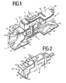
- Fig. 1 shows in principle a multiply offset longitudinal section through an empty coupling for fiber optic connector, designed here as a universal adapter 3 with a common housing 30, composed of two mirror-image identical front or rear housing parts 31 and 32. They abut the flanges 41 together and are there, for example glued or even held by a detent spring 5 and the frame 50 together; Alternatively, a positive connection 34 (FIG. 3b) of the parts 31, 32 is possible.
- the formed as a stub flanges 41 allow in a recess on the surface 402 of the housing 4 in the middle of the penetration of a spring tongue 51 which is integrally attached to the metal spring frame 50, from the extended end 52 a nose 53 protrudes, a front panel 10 (Fig. 6) behind and so can lock the adapter 3 in the front panel.
- the bracket 54 the nose 53 dissolves and the adapter can be pulled out of the front panel, without the connector must be removed from the adapter 3.
- the housing which may also be in one piece, has two connector receptacles 1 and 2 at the front and the rear, respectively.
- this representation is identical for the simplex adapter according to FIG. 2 and the duplex adapter according to FIG. 6, if of different wall thicknesses the housing is apart.
- the opening cross-sections and lateral guides in the walls of the adapter are tailored to the cross section of the connectors LC, LX.5 and MU 7, 8, 9.
- a centering 43 for the ferrule or light guide 20 (FIG. 3a, 3b) is embedded in the housing 30.
- the adapter includes a laser guard 44 which is held in the locked position by a spring 45 and which can be depressed by connectors or a cap ( Figure 3a).
- a bore 46 is used to engage a locking pin 61 of the cap 6, 60 (Fig. 3a) and 62 (Fig. 6).
- the flap pin 42 is used to open the mouth flap, not shown, a LX.5 connector 8 as is known in the art.
- the flap pin 42 is disposed at the end of a cantilevered resiliently displaceable tongue 421 which is an integral part of the side wall 401 of the housing 30 and, as will be described in Figs. 4 and 5, responds.
- the lock 28 for LX.5 connector 8 (FIGS. 3 b and 6) comprises on the housing 30 a latch 48 in the manner of a recess on the upper side 402 into which the two cams 81 on the elastic lever 82 can engage.
- the lock 29 for MU connector 9 comprises locking cams 49 in the side wall 401 of the housing; this cam in a recess, not shown, of the connector 9 and locks it so in the coupling.
- the lock 27 of the LC connector 7 is shown in Fig. 3a.
- Fig. 2 shows the adapter 3 'as a simplex connector complete with cap 60 and LC connector 7 and detent spring 5'. It can be clearly seen that the simplex housing 40 has on its surface in the side wall 403 and the top 402 between the flanges 41 and the largest housing cross-section 33 near the openings for the connector receptacles 1, 2 a recess in which the spring frame 50 for Plant comes and thus does not exceed the scope of the largest cross-section 33 of the housing.
- Fig. 3a show this simplex adapter 3 'in longitudinal section with a cap 60 on the receptacle 1 of the adapter and a fully inserted LC connector 7 on the rear receptacle 2, so that the light guide 20 is centered to the centering 43 and in FIG. 3b to the other without cap, but with inserted LX.5 connector 8.
- the LC connector 7 has on the locking device 27 on the connector housing 70 on a locking lever 73 with two-sided cam 72 which engage behind a latch 47 on the housing 40 when the connector is in the position shown. With the release lever 71 73 pressure can be exerted on locking lever, so that the resilient plastic lever to move down and the cams 70 disengage from the latch 47, so that the connector can be pulled.
- Fig. 3b shows a similar situation for the fully inserted LX.5 connector 8, but for the sake of clarity without the mouth flap.
- Light guide 20 and centering 43 lie in one axis; the locking device 28 is in operation.
- a cam 82 is mounted on both sides, which is locked in case 48 of the adapter housing 40 and 81 can be disengaged after depressing the elastic release lever.
- FIG. 4 shows a duplex adapter 3 "for the simultaneous and parallel connection of two light guides 20 within a coupling housing 4.
- Fig. 5 shows an adapter 3 'analogous to Fig. 2, 3a, 3b with partly inserted MU connector 9, but without its locking device, which was explained in Fig. 1.
- a LX.5 connector 8 and an LC connector 7 is shown at the top.
- the flap pin 42 necessary for the universal insertion of connectors has its own cam track 83 in the case of the LX.5 connector 8 and therefore remains in its position relative to the housing 4.
- the LC connector 7 or MU connector 9 pushes the connector with it an edge of its housing 70 and 90 against the flap pin 42 while the connectors are inserted into the adapter.
- the situation shows enlarged and correct position as a detail of Fig. 4a for the LC connector 7 and a mirror image of the MU connector 9 corresponding to the valve pin position in a circle.
- the elastic tongue 421 bends with the flap pin 42 to the side and clears the way for the connector 7 and 9, respectively.
- the side wall consists here for example only of the tongue 421 which is surrounded outside only by the spring frame 50 and 55 respectively.
- Fig. 6 shows an adapter 3 "with duplex housing 4 which in a Breakthrough 11 of a front panel 10 is inserted and there by means of spring 5 'on the spring frame 55, which surrounds the adapter 3 "arrested ..
- the lock can be solved by pressing the bracket 54 of the spring 5', as already described for itself.
- the caps 6 generally, or for simplex connector 60 and duplex connector 62 according to FIGS.
- 3a and 6 are preferably made of elastic plastic, have a locking pin 61 for clipping and fastening in a bore 46 on the housing 4, 30th , 40, an articulated elastic strap 63 for the pivoting away of the closure 64, 64 'of the cap to free the openings of the adapter or close, at the same time as dust protection and - in the case of adapters without laser protection flap 44 - also as eye protection.
- the front part 65 has a guide 66 for inserting therein an identification plate 67 provided with a label or identifier relating to the type of adapters, the connectors to be inserted, or the like.
Landscapes
- Physics & Mathematics (AREA)
- General Physics & Mathematics (AREA)
- Optics & Photonics (AREA)
- Mechanical Coupling Of Light Guides (AREA)
- Optical Couplings Of Light Guides (AREA)
Description
- Die Erfindung betrifft einen Adapter nach Art einer von einer Frontseite her in eine Frontplatte einsetzbaren und durch eine Feder arretierbaren Kupplung für Glasfaser-Steckverbinder mit einem ein- oder zweistückigem Gehäuse, welches wenigstens an einer Seite einen aus dem Querschnitt des Gehäuses hervorstehenden Flansch für die Anlage an der Frontplatte aufweist, mindestens einer zur Frontplatte frontseitigen und/ oder rückwärtigen Steckerverbinderaufnahme und mindestens einer formschlüssigen lösbaren Arretiereinrichtung für Steckverbinder,
- Kupplungen oder Adapter für Glasfaserstecker verbinden Glasfasern für Laserlicht. Derartige Kupplungen werden meist in einer Gehäusewand oder Frontplatte fixiert, so dass beiderseits der Frontplatte Steckeraufnahmen für Glasfaserstecker bereitstehen. Bis vor kurzem wurden derartige Glasfaserverbinder häufig in der Bauform der SC-Stecker oder SC-Konnektoren hergestellt. Jedoch werden diese zunehmend von kleineren Bauformen mit den Bezeichnungen LX.5, LC und MU abgelöst (Internet Anzeige am 06.08. 2001 um 15.25 Uhr unter der Adresse http://www.bicsi.org/prico8/sld001.htm - sld035.htm).
- LC-Konnektoren sind in der IEC 61751-20 und MU-Konnektoren in der IEC 61751-6 genormt. LX.5-Stecker sind noch nicht genormt; LX.5 ist eine registrierte Marke der Firma ADC Telecommunications, Inc.,US; derartige Stecker weisen verbesserte Eigenschaften auf (Internetdarstellung am 6.08.2001 um 15.28 Uhr unter http://stele.adc.com/Library/Literature/1236.pdf).
- SC-Konnektoren und entsprechende Kupplungen sind in der US-A 5,317,663 offenbart. Die Steckverbinder werden beiderseits durch Sperrnocken in der Kupplung, welche in Vertiefungen beiderseits des Verbinders greifen, gehalten, wenn die Lichtfaser-Zentrierungen ihre Sollposition erreicht haben.
Die dortigen Adapter für SC-Simplex-Verbinder sind mit in der Kupplung angeordneten Sperr-Klappen gegen Laserlicht ausgestattet. - Aus dem Internet war am 06.08.2001 um 15.35 unter der Adresse http://www.molex.com eine Kupplung des Typs "BSC II-Adapter with Shutter" für einen SC-Konnektor zu sehen. Unter Shutter wird eine schwenkbar angebrachte Klappe vor einer Steckeraufnahme-Öffnung verstanden, die eine Verletzung eines Monteurs durch Laserlicht beim Einstecken von SC-Konnektoren verhindern soll. Die Klappe weist einen Warnhinweis für Laser auf.
- Aus der EP 0 590 586 A1 ist eine aus zwei Teilen zusammengesetzte Kupplung für zwei MU-Verbinder bekannt, einer verkleinerten Weiterentwicklung des SC-Verbinders, die an einer Frontplatte mittels von einer Seite der Kupplung vorspringenden Flanschen befestigbar sind, wobei eine rückspringende Feder neben dem Flansch die Kupplung nach Einschieben in eine entsprechende Öffnung hinter der Frontplatte arretiert. Der Steckverbinder wird in der Kupplung ähnlich wie der SC-Verbinder gehalten.
- Aus der WO 00/16145 sind Glasfaserverbinder und Kupplungen der beschriebenen Art bekannt. Es werden kleiner bauende Verbinder des Typs LX.5 dargestellt, die eine Mündungsklappe vorn am Verbinder aufweisen, welche sich automatisch öffnet, sobald eine Laserlichtsperre gegen eine Rückstellfeder, angeordnet in der Kupplung, passiert ist. Während der Einsteckphase schiebt ein ortsfest in das Innere der Kupplung ragender Stift an dem Steckverbinder die durch eine Feder geschlossen gehaltene Mündungsklappe auf, damit die Glasfaser im Steckverbinder für die Lichtleitung zu einem in dem Adapter gegenüberliegenden Steckverbinder freigelegt wird. Der Verbinder rastet mit seinen zwei speziellen Nocken an einem federnden Hebel auf dem Gehäuse des Steckverbinders in eine komplementär gestaltete Falle an der Kupplung ein, die seitlich der Längsachse des Verbinders beziehungsweise der Kupplung angeordnet sind und verhaken sich dabei ineinander. Mittels des Hebels am Verbinder können die Nocken wieder aus ihrer Falle entriegelt werden.
- LC-Verbinder sind auch aus der EP 1091226 A1 bekannt. Sie haben eine mittig einseitig auf dem Verbinder angeordnete Sperr- und Löse-Hebeleinrichtung auf, mit dem eine formschlüssige Verbindung in der Kupplung gelöst werden kann, welche sich beim Einstecken des Verbinders ergibt. Die Verbindung entsteht durch zwei seitlich am Hebel angeordnete Nocken, die in eine gegenüberliegende Falle in der Kupplung einrasten, wenn der Verbinder seine Sollposition in der Kupplung erreicht hat. Auch diese Kupplungen haben Flansche und eine Rastfeder für eine Montage in einer Frontplatte.
- Es ist möglich, anstelle einer großbauenden SC-Kupplung zwei Kupplungen für LX.5, LC- oder MU-Verbinder in eine Frontplatte einzubauen. Obwohl die Steckverbinder teils genormt sind, treffen an unterschiedlichen Systemen unterschiedlicher Anwender unterschiedliche Steckverbinder zusammen, die aber nicht in dieselbe Kupplung passen.
- Unter der intemet-Adresse http://www.fiberplus.com/cpakit.htm war am 17.08.2001 ein Universaladaptersystem für die Steckverbinder Typen FC, ST, SC, SMA, D4 und BICONIC zu sehen und unter der Adresse http://www.fiberplus.com/upa.htm wurde ein Universal Panel Mount Adaptor beworben mit dem an einer Frontplatte die Typen ST oder FC miteinander bzw. zu DIN oder E2000 Steckverbindern gekoppelt werden können. Auch ein Adapter für die Kopplung von Typen MU zu LC durch einfaches mechanisches Verschrauben von Aufsteckhülsen für optische Fasern mit Gewinderingen. Der Einbau und Ausbau der Adapter ist zeitaufwendig und bedarf großer Fingerfertigkeit, insbesondere bei den kleinen Steckverbindern, deren Ferrule nur noch 1, 25 mm Durchmesser haben, gegenüber 2,5 mm bei den SC-Verbindem.
- Im Internet war am 06.08.2001 um 15Uhr 30 unter der Adresse http://www.senko.com/senkoadv/ sind neben LC-Steckem und MU-Steckem mit passenden Adaptern für eine Simplex- oder Duplex-Anwendung eine SC-LC-Adapter-Einrichtung dargestellt, die an einer Frontplatte anbringbar ist und frontseitig eine Steckeraufnahme für einen LC-Stecker und rückwärts eine Steckeraufnahme für einen SC-Stecker aufweist. Diese Kupplung kann nicht oder nur umständlich von der Frontseite her gelöst werden, nachdem sie von der Frontseite in die Frontplatte eingesetzt wurde und mittels einer Spreiz-Feder sich hinter der Frontplatte verhakte. Diese Art der Befestigung ist überwiegend bei allen Kupplungen anzutreffen, soweit diese nicht angeschraubt sind.
Bei den bisherigen Kupplungen und Verbindern ist nicht ersichtlich, wie diese von der Frontplatte gelöst werden können, ohne die Glasfaserverbindung zu trennen. - Aus der US-5,751,874 ist ein Adapter nach Art einer von einer Frontseite her in eine Frontplatte einsetzbaren und durch eine Feder arretierbaren Kupplung für Glasfasersteckverbinder bekannt, mit einem Gehäuse, welches wenigstens an einer Seite einen aus dem Querschnitt des Gehäuses hervorstehenden Flansch für die Anlage aus der Frontplatte aufweist. Der Adapter weist mindestens eine zur Frontplatte frontseitige und/oder rückwärtige Steckverbinderaufnahme sowie mindestens eine formschlüssige, lösbare Arretiereinrichtung für Steckverbinder auf. Dabei ist die Steckverbinderaufnahme zur Aufnahme von FC-, SC- oder ST-Steckverbindem ausgebildet.
- Aus der US-6,220,763 B1 ist eine Steckverbinderaufnahme zur Aufnahme von FC-, SC-, ST- oder LC-Steckverbindem bekannt.
- Aus der US6022149 ist ein Adapter nach Art einer von einer Frontseite her in eie Frontplatte einsetzbaren Kupplung für Glasfaserstecker bekannt. Der Adapter ist zur Aufnahme von Steckverbindern der Typen FC, SC und ST ausgebildert und besitzt ein Gehäuse mit einer Arretiervorrichtung mit einem verschiebbaren Stift.
- Der Erfindung liegt das technische Problem zugrunde, einen universellen Adapter für SFF-Steckverbinder (Small Form Factor) zu schaffen.
- Das zu Grunde liegende Problem wird erfindungsgemäß durch die Merkmale des Anspruches 1 gelöst. Weiterbildungen der Erfindung sind in den abhängigen Ansprüchen erfasst.
- Die Lösung für einen gattungsgemäßen Adapter besteht zunächst darin, dass jede Steckerverbinderaufnahme eine Öffnung für die wechselweise Aufnahme von mindestens zwei von drei unterschiedlichen Typen LX.5, LC und MU von Steckverbindern und je eine für den Typ passende Arretiereinrichtung hat, wobei mindestens eine Arretiereinrichtung für einen Steckertyp LX.5 vorhanden ist.
- Das Problem, den Stift zur Betätigung einer Mündungsklappe des Steckertyps LX.5 unterzubringen wurde gelöst, indem er an einem verschiebbaren Element an einer Seitenwand des Adapters angeordnet wird, vorzugsweise indem das verschiebbare Element in der Seitenwand als integrales Federelement ausgebildet wird. Dieses Element kann jedoch auch anders konstruiert werden, beispielsweise kann der Stift auch von den Steckverbindern - außer bei LX.5 - in Einsteckrichtung verschoben werden.
- Aufgrund der unterschiedlichen Arretiersysteme der Steckverbinder und deren Lage und Form sowie Funktion ist diese Lösung unbekannt und überraschend wie der umfangreiche Stand der Technik und die weltweite Verbreitung dieser Steckverbindertypen beweist.
Die Lösung ist am einfachsten zu realisieren, wenn die Arretiereinrichtungen für die Typen LX.5 und LC an derselben Seite der Kupplung angeordnet und die Arretiereinrichtung für den MU-Typ um 90° versetzt an anderen Seiten des Adapters angebracht wird.
Damit war auch die Weiterbildung dahin möglich, dass der Adapter als Simplex-Steck-Kupplung für die wechselweise Aufnahme aller drei Typen ausgebildet ist, während durch die Lage der Ferrule bedingt, als Duplex-Steck-Kupplung nur Adapter für die wechselweise Aufnahme der Stecker-Typen LX.5 und LC ausgebildet werden können. - In Weiterbildung der Erfindung soll bei Bedarf für Staubschutz oder Schutz vor dem Laserlicht die Kupplung geschlossen sein; erfindungsgemäß dadurch, dass die Öffnung der Aufnahme mit einer schwenkbar und lösbar an dem Gehäuse anbringbaren Kappe verschließbar ist. Vorzugsweise wird dazu die Kappe in eine Schnappeinrichtung , beispielsweise ein Loch für einen einrastenden Noppen, außen an dem Gehäuse eingesetzt. Zu Zwecken der Beschriftung wie über die Art der einzusetzenden Steckverbinder oder für einen Wamhinweis weist die Kappe außenseitig eine Führung für das Einschieben einer Kennzeichenplatte auf.
- Weiterhin soll der Adapter lösbar in einer Frontplatte von der Frontseite einsetzbar sein für dessen einfache Montage und Demontage. Dazu wird in einer schon für sich erfinderischen Weise der Adapter mit mindestens einer von der Frontseite her betätigbaren Rastfeder, angeordnet auf dem Gehäuse, zum Hintergreifen der Frontplatte und Lösen der Rastfeder aus der Frontplatte ausgestattet.
Vorzugsweise ist die Rastfeder als fliegende Federzunge ausgebildet ist, die sich durch eine Öffnung des Flansches und der Frontplatte erstrecken kann. Zur Montage bzw. Herstellung der Kupplung hat dabei die Rastfeder einen Federrahmen, der das Gehäuse an mindestens drei Seiten umgreift, sich durch den Flansch hindurch erstreckt und die Federzunge als integrales Teil aufweist. - Damit diese Bauweise möglichst wenig Platz braucht ist der Adapter so gestaltet, dass die Steckeraufnahmen an ihren Öffnungen den größten Gehäuse-Querschnitt bilden und die Gehäuseoberfläche in Richtung Flansch mit Rücksprüngen versehen ist für die Anlage von Teilen des Federrahmens, wobei der montierte Federrahmen den Querschnitt des Gehäuses an der Steckeraufnahme nicht überragt. Eine in solcher Weise angebrachte Kupplung kann aus der Frontplatte entnommen werden, ohne die Laserverbindung zu unterbrechen.
- An einem Ausführungsbeispiel soll die Erfindung anhand einer schematischen Zeichnung erläutert und die damit gelösten Probleme für den Fachmann aufgezeigt werden. Es zeigen:
- Fig. 1
- einen versetzten Längsschnitt in perspektivischer Sicht durch einen erfindungsgemäßen Adapter;
- Fig.2
- eine perspektivische Draufsicht auf einen ersten erfindungsgemäßen Simplex-Adapter mit einem gesteckten LC-Steckverbinder rückwärtig und einer Kappe frontseitig;
- Fig. 3a
- einen Längsschnitt durch einen Adapter gemäß Fig. 2;
- Fig. 3b
- einen Längsschnitt durch einen Adapter gemäß Fig.2, jedoch ist der LC-Steckverbinder ausgetauscht gegen einen LX.5-Steckverbinder und die Kappe entfernt;
- Fig. 4
- einen Längsschnitt durch einen Adapter gemäß Fig.6, jedoch ohne Kappe und mit teils eingesteckten LC und LX.5-Steckverbindern;
- Fig. 4a
- eine Einzelheit mit Raststift für LX.5-Verbinder;
- Fig. 5
- einen Schnitt durch einen Simplex-Adapter gemäß Fig. 2, jedoch ohne Kappe und mit teils eingestecktem Steckverbinder des Typs MU.
- Fig. 6
- eine perspektivische Draufsicht von der Frontseite auf einen in eine Frontplatte eingesetzten Duplex-Adapter mit rückwärtig eingesteckten Steckverbindern der Typen LC und LX.5 und frontseitiger, eine Kennung tragende, Kappe ;
- Identische Bezugszeichen verweisen auf Teile identischer oder ähnlicher Funktion. Die schematische Darstellung der Teile ist gegenüber der Realität etwa um den Faktor 5 bis 20 vergrößert.
- Fig. 1 zeigt im Prinzip einen mehrfach versetzten Längsschnitt durch eine leere Kupplung für Glasfaserverbinder, hier ausgebildet als Universal-Adapter 3 mit einem gemeinsamen Gehäuse 30, zusammengesetzt aus zwei spiegelbildlich identischen frontseitigen bzw. rückwärtigen Gehäuseteilen 31 bzw. 32. Sie stoßen an den Flanschen 41 zusammen und sind dort beispielsweise verklebt oder auch nur durch eine Rastfeder 5 bzw. deren Rahmen 50 zusammen gehalten; alternativ ist eine formschlüssige Verbindung 34 (Fig. 3b) der Teile 31, 32 möglich.
Die als Stummel ausgebildeten Flansche 41 erlauben in einer Aussparung auf der Oberfläche 402 des Gehäuses 4 mittig den Durchgriff einer Federzunge 51, die integral am metallenen Federrahmen 50 angebracht ist, von deren verlängertem Ende 52 eine Nase 53 hervorspringt, die eine Frontplatte 10 (Fig. 6) hintergreifen und so den Adapter 3 in der Frontplatte arretieren kann. Durch Druck auf den Bügel 54 löst sich die Nase 53 und der Adapter kann aus der Frontplatte gezogen werden, ohne dass die Steckverbinder aus dem Adapter 3 genommen werden müssen. - Das Gehäuse, welches auch einstückig sein kann, weist zwei SteckverbinderAufnahmen 1 bzw. 2 frontseitig bzw. rückwärtig auf.
Im Prinzip ist diese Darstellung identisch für den Simplex-Adapter gemäß Fig 2 und den Duplex-Adapter gemäß Fig. 6, wenn von verschiedenen Wanddicken des Gehäuses abgesehen wird. Die Öffnungsquerschnitte und seitlichen Führungen in den Wandungen des Adapters sind auf den Querschnitt der Steckverbinder der Typen LC, LX.5 und MU 7, 8, 9 zugeschnitten. - In Verlängerung der Öffnungen der Steckverbinderaufnahmen 1, 2 ist im Gehäuse 30 eine Zentrierung 43 für die Ferrule bzw. Lichtleiter 20 (Fig. 3a, 3b) eingelassen. Damit ein Monteur nicht unbeabsichtigt in einen Laserstrahl sehen kann, enthält der Adapter eine Laserschutzklappe 44, welche durch eine Feder 45 in der gezeigten Sperrstellung gehalten wird und die durch Steckverbinder oder eine Kappe (Fig. 3a) niedergedrückt werden kann.
Eine Bohrung 46 dient dem Einrasten eines Raststiftes 61 der Kappe 6, 60 (Fig. 3a) bzw. 62 (Fig. 6).
Der Klappenstift 42 dient dem Öffnen der nicht dargestellten Mündungsklappe eines LX.5-Steckverbinders 8 wie dies aus dem Stand der Technik für sich bekannt ist. Der Klappenstift 42 ist am Ende einer fliegend gelagerten elastisch verschiebbaren Zunge 421 angeordnet, die integraler Teil der Seitenwandung 401 des Gehäuses 30 ist und wie in Fig. 4 und 5 noch zu beschreiben ist, reagiert. Die Arretierung 28 für LX.5-Steckverbinder 8 (Fig. 3b und 6) umfasst am Gehäuse 30 eine Falle 48 nach Art einer Ausnehmung an dessen Oberseite 402 in die die beiden Nocken 81 am elastischen Hebel 82 einrasten können.
Die Arretierung 29 für MU-Steckverbinder 9 umfasst Sperrnocken 49 in der Seitenwandung 401 des Gehäuses; dieser Nocken in eine nicht dargestellte Vertiefung des Steckverbinders 9 und arretiert ihn so in der Kupplung.
Die Arretierung 27 des LC-Steckverbinders 7 wird in Fig. 3a dargestellt. - Fig. 2 zeigt den Adapter 3' als Simplexverbinder komplett mit Kappe 60 und LC-Steckverbinder 7 und Rastfeder 5'. Es ist deutlich zusehen, dass das Simplex-Gehäuse 40 an seiner Oberfläche in der Seitenwandung 403 und der Oberseite 402 zwischen den Flanschen 41 und dem größten Gehäusequerschnitt 33 nahe den Öffnungen für die Steckverbinderaufnahmen 1, 2 eine Vertiefung hat, in der der Federrahmen 50 zur Anlage kommt und damit den Umfang des größten Querschnitt 33 des Gehäuses nicht überragt.
- Fig. 3a zeigen diesen Simplex-Adapter 3' im Längsschnitt mit einer Kappe 60 an der Aufnahme 1 des Adapters und einen voll eingesteckten LC-Steckverbinder 7 an der rückwärtigen Aufnahme 2, so dass der Lichtleiter 20 mittig zur Zentrierung 43 liegt und in Fig. 3b zum anderen ohne Kappe, aber mit eingestecktem LX.5 Steckverbinder 8.
- Der LC-Steckverbinder 7 weist an der Arretiereinrichtung 27 am Steckergehäuse 70 einen Arretierhebel 73 mit beidseitigen Nocken 72 auf, die hinter eine Falle 47 am Gehäuse 40 einrasten, wenn der Steckverbinder in der gezeigten Position ist. Mit dem Lösehebel 71 kann auf Arretierhebel 73 Druck ausgeübt werden, so dass sich die aus elastischen Kunststoff bestehenden Hebel nach unten bewegen und die Nocken 70 aus der Falle 47 ausrasten, damit der Steckverbinder gezogen werden kann.
- Fig. 3b zeigt eine ähnliche Situation für den voll eingesteckten LX.5 Steckverbinder 8, jedoch der Übersicht halber ohne die Mündungsklappe. Lichtleiter 20 und Zentrierung 43 liegen in einer Achse; die Arretiereinrichtung 28 ist in Funktion. Am Lösehebel 81 des Steckergehäuses 80 ist beiderseits ein Nocken 82 angebracht, der in Falle 48 des Adapter-Gehäuses 40 eingerastet ist und nach Niederdrücken des elastischen Lösehebels 81 wieder ausgerastet werden kann.
- Fig. 4 zeigt einen Duplex-Adapter 3" für das gleichzeitige und parallele Verbinden zweier Lichtleiter 20 innerhalb eines Kupplungsgehäuses 4.
- Fig. 5 zeigt einen Adapter 3' analog Fig. 2, 3a, 3b mit teils eingestecktem MU-Steckverbinder 9, jedoch ohne dessen Arretiereinrichtung, die bei Fig. 1 erläutert wurde.
- In Fig. 4 ist oben ein LX.5-Steckverbinder 8 und unten ein LC-Steckverbinder 7 dargestellt. Der für das universelle Stecken von Verbindern notwendige Klappenstift 42 hat beim LX.5-Verbinder 8 eine eigene Nockenbahn 83 und verbleibt daher in seiner Position relativ zum Gehäuse 4. Beim LC-Verbinder 7 bzw. MU-Verbinder 9 wird dagegen stößt der Verbinder mit einer Kante seines Gehäuses 70 bzw. 90 gegen den Klappenstift 42 während die Verbinder in den Adapter eingeschoben werden. Die Situation zeigt vergrößert und lagegerecht als Einzelheit die Fig. 4a für den LC-Verbinder 7 und spiegelbildlich für den MU-Verbinder 9 entsprechend der Klappenstift-Lage im Kreis. Werden die Verbinder weiter in den Adapter geschoben, verbiegt sich die elastische Zunge 421 mit dem Klappenstift 42 zur Seite und macht den Weg für den Steckverbinder 7 bzw. 9 frei. Die Seitenwandung besteht hier beispielsweise nur aus der Zunge 421 die außen nur von dem Federrahmen 50 bzw. 55 umgeben ist.
- Fig. 6 zeigt einen Adapter 3" mit Duplex-Gehäuse 4 welches in einen Durchbruch 11 einer Frontplatte 10 eingesetzt ist und dort mittels Feder 5' am Federrahmen 55, der den Adapter 3" umgibt, arretiert ist. Die Arretierung läßt sich durch Drücken des Bügels 54 der Feder 5', wie für sich bereits beschrieben, lösen.
Rückseitig sind, wie in Fig. 4 dargestellt, zwei Verbinder 7 bzw. 8 des Typs LC bzw. LX.5 eingesetzt, während frontseitig eine Kappe 62 den Adapter bzw. dessen beide Öffnungen gemeinsam verschließt.
Die Kappen 6 allgemein, bzw. für Simplex-Verbinder 60 bzw. für Duplex-Verbinder 62 gemäß den Fig. 3a und 6 bestehen vorzugsweise aus elastischem Kunststoff, haben einem Raststift 61 für das Einclipsen und Befestigen in einer Bohrung 46 am Gehäuse 4, 30, 40, einen gelenkigen elastischen Bügel 63 für das Wegschwenken des Verschlusses 64, 64' der Kappe, um die Öffnungen des Adapters frei zu geben oder zu verschließen, zugleich als Staubschutz und - bei Adaptern ohne Laserschutzklappe 44 - auch als Augenschutz. Das Frontteil 65 weist eine Führung 66 auf, um dort eine Kennzeichnungsplatte 67 einzusetzen, die mit einer Beschriftung oder Kennung versehen ist, betreffend die Art der Adapter, der einzusetzenden Steckverbinder oder ähnliches, aufzunehmen. -
- 1
- Steckerverbinderaufnahme frontseitig
- 2
- Steckerverbinderaufnahme rückwärtig
- 3, 3', 3"
- Adapter
- 4
- Gehäuse Duplex-Adapter
- 5,5'
- Rastfeder
- 6
- Kappe
- 7
- LC-Steckverbinder
- 8
- LX.5-Steckverbinder
- 9
- MU-Steckverbinder
- 10
- Frontplatte
- 11
- Durchbruch
- 20
- Lichtleiter
- 27
- Arretierung LC
- 28
- Arretierung LX.5
- 29
- Arretierung MU
- 30
- Adaptergehäuse
- 31
- Adapterteil frontseitig
- 32
- Adapterteil rückwärtig
- 33
- Adapterquerschnitt größter
- 34
- Verbindung
- 40
- Gehäuse Simplex-Adapter
- 401
- Seitenwand
- 402
- Oberseite
- 403
- Seitenwand
- 41
- Flansch
- 42
- Klappenstift
- 421
- Zunge
- 43
- Zentrierung
- 44
- Laserschutzklappe
- 45
- Feder
- 46
- Bohrung
- 47
- Falle-LC-Verbinder
- 48
- Falle LX.5-Verbinder
- 49
- Sperrnocke MU-Verbinder
- 50
- Federrahmen Simplex-Verbinder
- 51
- Federzunge
- 52
- Ende
- 53
- Nase
- 54
- Bügel
- 55
- Federrahmen Duplex-Verbinder
- 60
- Kappe Simplex-Verbinder
- 61
- Raststift
- 62
- Kappe Duplex-Verbinder
- 63
- Bügel
- 64, 64'
- Verschluss
- 65
- Frontteil
- 66
- Führung
- 67
- Kennzeichenplatte
- 70
- Steckergehäuse
- 71
- Lösehebel
- 72
- Nocken
- 73
- Arretierhebel
- 80
- Steckergehäuse
- 81
- Lösehebel
- 82
- Nocken
- 90
- Steckergehäuse
Claims (12)
- Adapter (3,3',3") nach Art einer von einer Frontseite her in eine Frontplatte (10) einsetzbaren und durch eine Feder (5,5') arretierbaren Kupplung für Glasfaser-Steckverbinder mit- einem ein- oder zweistückigem Gehäuse (4,30,40), welches wenigstens an einer Seite einen aus dem Querschnitt des Gehäuses (4,30,40) hervorstehenden Flansch (41) für die Anlage an der Frontplatte (10) aufweist,- mindestens einer zur Frontplatte (10) frontseitigen und/ oder rückwärtigen Steckerverbinderaufnahme (1,2),- mindestens einer formschlüssigen lösbaren Arretiereinrichtung (27,28,29) für Steckverbinder (7,8,9),dadurch gekennzeichnet, dass jede Steckverbinderaufnahme (1,2) eine Öffnung für die wechselweise Aufnahme von mindestens zwei von drei unterschiedlichen Typen LX.5, LC und MU von Steckverbindern (7, 8, 9) und je eine für den Typ passende Arretiereinrichtung (27, 28, 29) hat,
wobei mindestens eine Arretiervorrichtung (27) für einen Steckertyp LX.5 (7) vorhanden ist und ein Stift (42) zur Betätigung einer Mündungsklappe des Steckertyps LX.5 (7) an einem verschiebbaren Element (421) an einer Seitenwand (401) des Adapters angeordnet ist. - Adapter nach Anspruch 1, dadurch gekennzeichnet, dass das verschiebbare Element (421) in der Seitenwand (401) als integrales Federelement ausgebildet ist.
- Adapter nach Anspruch 1 oder 2, dadurch gekennzeichnet, dass die Arretiereinrichtung (27, 28) für die Typen LX.5 und LC (7, 8) an derselben Seite (402) des Adapters (3, 3', 3") angeordnet sind.
- Adapter nach einem der vorangegangenen Ansprüche, dadurch gekennzeichnet, dass der Adapter als Duplex-Steck-Kupplung für die wechselweise Aufnahme der Stecker-Typen LX.5 und LC (7, 8) ausgebildet ist.
- Adapter nach Anspruch 3, dadurch gekennzeichnet, dass der Adapter (3, 3', 3") als Simplex-Steck-Kupplung für die wechselweise Aufnahme aller drei Typen (7, 8, 9) ausgebildet ist, wobei die Arretiereinrichtung für den Stecker-Typ MU um 90° versetzt an anderen Seiten des Adapters angebracht ist.
- Adapter nach einem der vorhergehenden Ansprüche, dadurch gekennzeichnet, dass die Öffnung der Aufnahme (1, 2) mit einer schwenkbar und lösbar an dem Gehäuse (4, 30, 40) anbringbaren Kappe (6, 60, 62) verschließbar ist.
- Adapter nach einem der vorhergehenden Ansprüche, dadurch gekennzeichnet, dass die schwenkbare und lösbare Kappe (6, 60, 62) in eine Schnappeinrichtung (46) außen an dem Gehäuse (4, 30, 40) einsetzbar ist.
- Adapter nach einem der vorhergehenden Ansprüche, dadurch gekennzeichnet, dass die Kappe (6, 60, 62) außenseitig mit einer Führung (66) für das Einschieben einer Kennzeichenplatte (67) ausgestattet ist.
- Adapter nach einem der vorangegangenen Ansprüche, dadurch gekennzeichnet, dass der Adapter mindestens eine von der Frontseite her betätigbare Rastfeder (5, 5'), angeordnet auf dem Gehäuse (4, 30, 40), zum Hintergreifen der Frontplatte (10) und Lösen der Rastfeder (5, 5') aus der Frontplatte (10) aufweist.
- Adapter nach einem der vorhergehenden Ansprüche, dadurch gekennzeichnet, dass die Rastfeder (5, 5') als fliegende Federzunge (51) ausgebildet ist, die sich durch eine Öffnung des Flansches (41) und der Frontplatte (10, 11) erstrecken kann.
- Adapter nach einem der vorhergehenden Ansprüche, dadurch gekennzeichnet, dass die Rastfeder (5, 5') einen Federrahmen (50, 55) hat, der das Gehäuse (4, 30, 40) an mindestens drei Seiten (401, 402, 403) umgreift, sich durch den Flansch (41) hindurch erstreckt und die Federzunge (51) als integrales Teil aufweist.
- Adapter nach einem der vorhergehenden Ansprüche, dadurch gekennzeichnet, dass die Steckeraufnahmen (1, 2) an ihren Öffnungen den größten Gehäuse-Querschnitt (33) bilden und die Gehäuseoberfläche in Richtung Flansch (41) mit Rücksprüngen versehen ist für die Anlage von Teilen des Federrahmens (50, 55), wobei der montierte Federrahmen den Querschnitt (33) des Gehäuses (4, 40, 40) an der Steckeraufnahme (1, 2) nicht überragt.
Priority Applications (1)
| Application Number | Priority Date | Filing Date | Title |
|---|---|---|---|
| CY071100806T CY1107055T1 (el) | 2001-08-23 | 2007-06-20 | Προσαρμογεας γενικης χρησεως |
Applications Claiming Priority (3)
| Application Number | Priority Date | Filing Date | Title |
|---|---|---|---|
| DE2001141449 DE10141449A1 (de) | 2001-08-23 | 2001-08-23 | Universal-Adapter |
| DE10141449 | 2001-08-23 | ||
| PCT/EP2002/008112 WO2003019260A2 (de) | 2001-08-23 | 2002-07-27 | Krone gmbh |
Publications (2)
| Publication Number | Publication Date |
|---|---|
| EP1419408A2 EP1419408A2 (de) | 2004-05-19 |
| EP1419408B1 true EP1419408B1 (de) | 2007-03-28 |
Family
ID=7696438
Family Applications (1)
| Application Number | Title | Priority Date | Filing Date |
|---|---|---|---|
| EP02762379A Expired - Lifetime EP1419408B1 (de) | 2001-08-23 | 2002-07-27 | Universaladapter |
Country Status (23)
| Country | Link |
|---|---|
| US (2) | US7182524B2 (de) |
| EP (1) | EP1419408B1 (de) |
| JP (1) | JP2005501289A (de) |
| KR (1) | KR100742550B1 (de) |
| CN (1) | CN1287177C (de) |
| AR (1) | AR035290A1 (de) |
| AT (1) | ATE358284T1 (de) |
| AU (1) | AU2002327890B2 (de) |
| BR (1) | BR0212103A (de) |
| CA (1) | CA2455258C (de) |
| CY (1) | CY1107055T1 (de) |
| DE (2) | DE10141449A1 (de) |
| DK (1) | DK1419408T3 (de) |
| ES (1) | ES2284914T3 (de) |
| IL (2) | IL160062A0 (de) |
| MX (1) | MXPA04001557A (de) |
| NZ (1) | NZ530983A (de) |
| PT (1) | PT1419408E (de) |
| RU (1) | RU2288492C2 (de) |
| SA (1) | SA02230335B1 (de) |
| TW (1) | TWI255359B (de) |
| WO (1) | WO2003019260A2 (de) |
| ZA (1) | ZA200401398B (de) |
Families Citing this family (65)
| Publication number | Priority date | Publication date | Assignee | Title |
|---|---|---|---|---|
| US5883995A (en) | 1997-05-20 | 1999-03-16 | Adc Telecommunications, Inc. | Fiber connector and adapter |
| DE10141449A1 (de) * | 2001-08-23 | 2003-03-13 | Krone Gmbh | Universal-Adapter |
| JP4328712B2 (ja) * | 2004-03-10 | 2009-09-09 | 株式会社精工技研 | 光コネクタプラグ及び光コネクタ |
| DE102004049697A1 (de) | 2004-10-12 | 2006-04-20 | Adc Gmbh | Hybrid-Adapter |
| DE102004054535B3 (de) * | 2004-11-05 | 2006-03-30 | Adc Gmbh | Steckverbinder für Leiterplatten |
| US7261472B2 (en) * | 2005-01-12 | 2007-08-28 | Illum Technologies, Inc. | Ultra-small, form factor single fiber optical interconnect system, with push-push type insertion/withdrawal mechanism and shuttered modular connector and shuttered adapter and method for using same |
| US7284912B2 (en) * | 2005-01-12 | 2007-10-23 | Illum Technologies, Inc. | Multi fiber optical interconnect system, with push—push type insertion/withdrawal mechanism, MT-type connector and shuttered adapter and method for using same |
| RU2368045C1 (ru) * | 2005-08-08 | 2009-09-20 | Рейхл Энд Де-Массари Аг | Предохранительное приспособление для штекера (коммутационное предохранение) |
| EP2035874B1 (de) * | 2006-06-21 | 2019-03-20 | Firecomms Limited | Optischer stecker |
| US7543994B2 (en) | 2006-10-19 | 2009-06-09 | Avago Technologies Fiber Ip (Singapore) Pte. Ltd. | Multi-optical fiber connector module for use with a transceiver module and method for coupling optical signals between the transceiver module and multiple optical fibers |
| CN100570420C (zh) * | 2006-10-19 | 2009-12-16 | 安华高科技光纤Ip(新加坡)私人有限公司 | 可堆叠多光纤连接器模块、使之对准并耦合光信号的装置 |
| US7806599B2 (en) * | 2007-05-04 | 2010-10-05 | Illum Technologies, Inc. | Super miniature, single fiber optical interconnect system with parallel slider push-push type insertion/withdrawal mechanism and method for using same |
| JP4780794B2 (ja) * | 2007-06-20 | 2011-09-28 | サンコール株式会社 | シャッタアッセンブリ |
| JP4863393B2 (ja) * | 2007-06-20 | 2012-01-25 | サンコール株式会社 | シャッタアッセンブリ |
| US7717625B2 (en) * | 2007-08-13 | 2010-05-18 | Illum Technologies, Inc. | High density fiber optic interconnect system with push-release mechanism and method for using same |
| EP2220729B1 (de) * | 2007-11-13 | 2017-09-27 | Linak A/S | Betätigungssystem |
| US7555191B1 (en) * | 2008-01-30 | 2009-06-30 | Joshua John Edward Moore | Self-locking unidirectional interposer springs for optical transceiver modules |
| DE102009007596B4 (de) * | 2009-02-05 | 2011-06-01 | Phoenix Contact Gmbh & Co. Kg | Elektrischer Steckverbinder |
| JP2010211024A (ja) * | 2009-03-11 | 2010-09-24 | Fujitsu Ltd | Lcアダプタ |
| US20100316345A1 (en) * | 2009-04-20 | 2010-12-16 | Michael Wentworth | Fiber optic panel and method |
| US9720183B2 (en) | 2009-08-24 | 2017-08-01 | Panduit Corp. | Fiber optic adapter with enhanced alignment |
| CN102338910A (zh) * | 2010-07-22 | 2012-02-01 | 普泰光電股份有限公司 | 制造lc型单件式光纤转接器的方法 |
| DE102010038266B4 (de) * | 2010-10-19 | 2013-05-23 | Harting Electric Gmbh & Co. Kg | Mehrteiliges Steckverbindergehäuse |
| DE102011011523B4 (de) * | 2011-02-17 | 2013-05-29 | Tyco Electronics Services Gmbh | Faseroptische Verbindungsanordnung und Adapterhülse |
| TWI435129B (zh) * | 2011-06-14 | 2014-04-21 | Ezontek Technologies Co Ltd | 具有遮光件之光纖適配器 |
| CN202995082U (zh) * | 2011-06-27 | 2013-06-12 | 3M创新有限公司 | 用于端接光纤的光纤连接器 |
| US8634901B2 (en) | 2011-09-30 | 2014-01-21 | Covidien Lp | ECG leadwire system with noise suppression and related methods |
| CN103048741A (zh) * | 2011-10-17 | 2013-04-17 | 普泰光电股份有限公司 | 具有防尘功能的光纤连接器与光纤适配器 |
| CN103091789A (zh) * | 2011-10-27 | 2013-05-08 | 东侑光电股份有限公司 | 光纤适配器的防护盖 |
| US9196997B2 (en) * | 2011-11-10 | 2015-11-24 | Panduit Corp. | Shuttered LC adapter |
| US9494746B2 (en) | 2011-11-10 | 2016-11-15 | Panduit Corp. | Shuttered LC adapter |
| US10215926B2 (en) * | 2011-12-14 | 2019-02-26 | Commscope Technologies Llc | Multi-fiber fiber optic connection system with flexible, insertable pins |
| US9122020B2 (en) * | 2012-06-06 | 2015-09-01 | Tyco Electronics Corporation | Connector assembly having a slidable connector |
| KR101394859B1 (ko) * | 2012-09-05 | 2014-05-13 | 현대자동차주식회사 | 자동차의 bms 커넥터 |
| US9354404B2 (en) * | 2012-12-28 | 2016-05-31 | Intel Corporation | Datacenter optics (DCO) edge mount transceiver assembly and plug connector |
| GB2522550B (en) * | 2013-02-06 | 2017-11-01 | Xyratex Tech Ltd | Optical connector |
| US9128256B2 (en) | 2013-02-06 | 2015-09-08 | Xyratex Technology Limited | Optical connector |
| JP6426145B2 (ja) * | 2013-03-21 | 2018-11-21 | コーニング リサーチ アンド ディヴェロップメント コーポレイション | 外被付きケーブル用光コネクタ |
| JP6400892B2 (ja) * | 2013-09-17 | 2018-10-03 | 三和電気工業株式会社 | Lc形光コネクタの防塵シャッタ内蔵アダプタ |
| CN103869427B (zh) * | 2013-10-01 | 2015-08-12 | 深圳市好通家实业有限公司 | 一种光纤连接器 |
| US10048447B2 (en) | 2013-10-31 | 2018-08-14 | CommScope Connectivity Belgium BVBA | Fiber optic connection system |
| US10320109B2 (en) * | 2014-04-09 | 2019-06-11 | Level 3 Communications, Llc | Cable terminator |
| US9348098B2 (en) | 2014-04-10 | 2016-05-24 | Avago Technologies General Ip (Singapore) Pte. Ltd. | Optical port adapted to mate with plugs of different types |
| EP2993502B1 (de) * | 2014-09-04 | 2019-10-23 | Corning Optical Communications LLC | Optischer Adapter zur Montage an einen Behälter zum optischen Verbinden anschlussfertiger optischer Kabel |
| US10162126B2 (en) | 2014-12-01 | 2018-12-25 | Commscope Asia Holdings B.V. | Multi-fiber optic connector with pivotally-aligned ferrule and resilient alignment pins |
| EP3311207A4 (de) | 2015-06-19 | 2019-02-20 | Commscope Technologies LLC | Ferrule mit faseroptischem verbinder mit verbessertem ausrichtungsmechanismus |
| JP2017151338A (ja) * | 2016-02-26 | 2017-08-31 | 三和電気工業株式会社 | 光アダプタ用ホルダ装置 |
| TWI608261B (zh) * | 2016-11-29 | 2017-12-11 | 普泰光電股份有限公司 | 具有遮蔽件之光纖適配器 |
| CN111133350A (zh) * | 2017-09-20 | 2020-05-08 | 莫列斯有限公司 | 用于光纤适配器的挡光闸门 |
| TWM561217U (zh) * | 2018-01-09 | 2018-06-01 | Advanced Connectek Inc | 光纖適配器 |
| TWI677724B (zh) * | 2018-04-27 | 2019-11-21 | 楊沐晨 | 光纖適配器 |
| TWM567872U (zh) * | 2018-06-27 | 2018-10-01 | 連訊通信股份有限公司 | 光學連接器的遮光適配器 |
| US10677999B2 (en) * | 2018-08-22 | 2020-06-09 | Hewlett Packard Enterprise Development Lp | Duplex-modulo optical blindmate connector having a carrier plate and connector housing |
| WO2020046709A1 (en) | 2018-08-29 | 2020-03-05 | Commscope Technologies Llc | Fiber optic connectors, fiber optic adapters and related fiber optic connection systems |
| US11262510B2 (en) | 2018-10-25 | 2022-03-01 | Senko Advanced Components, Inc. | Rattle-free panel hook for a fiber optic adapter outer housing |
| TW202029591A (zh) | 2018-12-02 | 2020-08-01 | 美商扇港元器件有限公司 | 用於接收光纖連接器之具粉塵擋門總成的光纖配接器 |
| US12164153B2 (en) | 2019-01-09 | 2024-12-10 | Commscope Technologies Llc | Fiber optic adapter with integrally molded structures |
| US10944245B2 (en) * | 2019-02-18 | 2021-03-09 | Arens Controls Company, Llc | Method for a flexible connection scheme and protective enclosure for electronics for the chassis of a junction box or charge switch unit for an electric vehicle |
| CN110196153A (zh) * | 2019-05-22 | 2019-09-03 | 上海嘉慧光电子技术有限公司 | 一种基于双联lc的可拆卸探测结构件 |
| EP4004619A4 (de) * | 2019-07-26 | 2023-08-09 | CommScope Technologies LLC | Zwischen verschiedenen polaritätsarten umwandelbare faseroptische adapter |
| JP7387407B2 (ja) * | 2019-11-27 | 2023-11-28 | 日本航空電子工業株式会社 | コネクタ組立体 |
| ES3057046T3 (en) | 2020-10-08 | 2026-02-25 | Applied Med Resources | Lighted surgical access system |
| EP4327150A4 (de) | 2021-04-23 | 2025-03-12 | CommScope Technologies LLC | Panelsystem mit verwalteter konnektivität |
| RU208403U1 (ru) * | 2021-06-03 | 2021-12-16 | федеральное государственное бюджетное образовательное учреждение высшего образования "Первый Санкт-Петербургский государственный медицинский университет имени академика И.П. Павлова" Министерства здравоохранения Российской Федерации | Насадка для защиты от лазерного воздействия струйного катетера для искусственной вентиляции легких при лазерной хирургии гортани и трахеи |
| TWM643064U (zh) * | 2023-03-30 | 2023-06-21 | 建毅科技股份有限公司 | 光纖適配器 |
Family Cites Families (35)
| Publication number | Priority date | Publication date | Assignee | Title |
|---|---|---|---|---|
| SU1695762A1 (ru) * | 1990-01-22 | 1996-04-10 | Научно-исследовательский институт дальней радиосвязи | Многоконтактный оптический соединитель |
| US5333221A (en) * | 1992-06-30 | 1994-07-26 | The Whitaker Corporation | Universal adapter for optical connectors |
| US5274729A (en) * | 1992-07-30 | 1993-12-28 | At&T Bell Laboratories | Universal optical fiber buildout system |
| EP0590586A1 (de) | 1992-09-29 | 1994-04-06 | Tosoh Corporation | Aus Zirkonoxid hergestellte Steckerteile |
| US5244402A (en) * | 1992-12-18 | 1993-09-14 | International Business Machines Corporation | Socket for multiple types of telephone plugs |
| DE69408344T2 (de) | 1993-02-24 | 1998-05-20 | Sumitomo Wiring Systems | Optischer Stecker |
| US5317663A (en) | 1993-05-20 | 1994-05-31 | Adc Telecommunications, Inc. | One-piece SC adapter |
| US5561727A (en) * | 1994-02-15 | 1996-10-01 | Sumitomo Electric Industries, Ltd. | Card-shaped optical data link device |
| US5506922A (en) | 1994-08-01 | 1996-04-09 | Molex Incorporated | Fiber optic component assembly with a movable protective shield |
| JPH08138785A (ja) * | 1994-11-10 | 1996-05-31 | Yazaki Corp | シャッター機構付コネクタ |
| US5751874A (en) | 1996-09-13 | 1998-05-12 | Nuvisions International, Inc. | Coupling device for linking optical fiber connectors |
| US5896480A (en) * | 1996-10-22 | 1999-04-20 | Stewart Connector Systems, Inc. | Optical interconnection system |
| US5956444A (en) * | 1997-02-13 | 1999-09-21 | Amphenol Corporation | Radiation absorbing shield for fiber optic systems |
| US5896477A (en) * | 1997-05-16 | 1999-04-20 | Lucent Technologies Inc. | Optical fiber coupling buildout system |
| US6142676A (en) * | 1997-05-20 | 2000-11-07 | Adc Telecommunications, Inc. | Fiber connector and adaptor |
| US5883995A (en) * | 1997-05-20 | 1999-03-16 | Adc Telecommunications, Inc. | Fiber connector and adapter |
| US6022149A (en) * | 1998-02-05 | 2000-02-08 | So; Vincent | Fibre optic adaptor |
| US6095694A (en) * | 1998-05-11 | 2000-08-01 | Nuvisions International, Inc. | Fiber optic component coupling apparatus with locking capability and methods of fabrication and use thereof |
| US6102581A (en) | 1998-06-16 | 2000-08-15 | Lucent Technologies Inc. | Optical adapter including a ferrule assembly |
| US6220763B1 (en) * | 1998-09-04 | 2001-04-24 | Lucent Technologies Inc. | Optical fiber buildout system |
| US6149315A (en) * | 1998-09-04 | 2000-11-21 | Lucent Technologies Inc. | Side load resistant buildout |
| DE19905240C2 (de) | 1999-02-02 | 2001-12-06 | Infineon Technologies Ag | Kopplungshülse |
| US6524014B2 (en) * | 1999-04-01 | 2003-02-25 | Fitel Usa Corp. | Universal modular optical fiber buildout |
| US6293710B1 (en) | 1999-10-06 | 2001-09-25 | Lucent Technologies Inc. | Optical connector having a one-piece housing |
| US6174190B1 (en) * | 1999-10-26 | 2001-01-16 | Keith Frank Tharp | Connector having a slide rail latch release |
| US6367984B1 (en) * | 1999-11-10 | 2002-04-09 | Lucent Technologies, Inc. | Optical fiber adapter |
| US6685362B2 (en) * | 2000-03-24 | 2004-02-03 | Tyco Electronics Corporation | Shielded adapter assembly |
| US6508593B1 (en) * | 2000-05-09 | 2003-01-21 | Molex Incorporated | Universal panel mount system for fiber optic connecting devices |
| DE10047898A1 (de) | 2000-09-26 | 2002-04-25 | Krone Ag | Kupplungseinrichtung für Glasfaserverbinder |
| AU2002220560B2 (en) * | 2000-09-26 | 2006-06-01 | Adc Gmbh | Coupling device for glass fiber connectors |
| US6543941B1 (en) * | 2000-10-18 | 2003-04-08 | Fitel Usa Corp. | Jack receptacle having optical and electrical ports |
| US6852386B2 (en) * | 2001-03-08 | 2005-02-08 | Norbord Inc. | Composite board with OSB faces |
| DE10141449A1 (de) * | 2001-08-23 | 2003-03-13 | Krone Gmbh | Universal-Adapter |
| US6872008B2 (en) * | 2002-03-22 | 2005-03-29 | Ykk Corporation | Conversion sleeve and optical adapter |
| TW547659U (en) * | 2002-05-24 | 2003-08-11 | Hon Hai Prec Ind Co Ltd | Optical connector |
-
2001
- 2001-08-23 DE DE2001141449 patent/DE10141449A1/de not_active Withdrawn
-
2002
- 2002-07-27 EP EP02762379A patent/EP1419408B1/de not_active Expired - Lifetime
- 2002-07-27 IL IL16006202A patent/IL160062A0/xx unknown
- 2002-07-27 CA CA 2455258 patent/CA2455258C/en not_active Expired - Fee Related
- 2002-07-27 RU RU2004108207A patent/RU2288492C2/ru not_active IP Right Cessation
- 2002-07-27 AT AT02762379T patent/ATE358284T1/de active
- 2002-07-27 DK DK02762379T patent/DK1419408T3/da active
- 2002-07-27 NZ NZ530983A patent/NZ530983A/en not_active IP Right Cessation
- 2002-07-27 ES ES02762379T patent/ES2284914T3/es not_active Expired - Lifetime
- 2002-07-27 JP JP2003524068A patent/JP2005501289A/ja active Pending
- 2002-07-27 US US10/487,656 patent/US7182524B2/en not_active Expired - Fee Related
- 2002-07-27 PT PT02762379T patent/PT1419408E/pt unknown
- 2002-07-27 KR KR20047002580A patent/KR100742550B1/ko not_active Expired - Fee Related
- 2002-07-27 WO PCT/EP2002/008112 patent/WO2003019260A2/de not_active Ceased
- 2002-07-27 DE DE50209839T patent/DE50209839D1/de not_active Expired - Lifetime
- 2002-07-27 MX MXPA04001557A patent/MXPA04001557A/es active IP Right Grant
- 2002-07-27 BR BR0212103A patent/BR0212103A/pt not_active IP Right Cessation
- 2002-07-27 AU AU2002327890A patent/AU2002327890B2/en not_active Ceased
- 2002-07-27 CN CNB02816475XA patent/CN1287177C/zh not_active Expired - Fee Related
- 2002-08-02 TW TW91117443A patent/TWI255359B/zh not_active IP Right Cessation
- 2002-08-21 AR ARP020103131 patent/AR035290A1/es active IP Right Grant
- 2002-09-25 SA SA02230335A patent/SA02230335B1/ar unknown
-
2004
- 2004-01-26 IL IL160062A patent/IL160062A/en not_active IP Right Cessation
- 2004-02-20 ZA ZA2004/01398A patent/ZA200401398B/en unknown
-
2007
- 2007-01-19 US US11/624,704 patent/US7703987B2/en not_active Expired - Lifetime
- 2007-06-20 CY CY071100806T patent/CY1107055T1/el unknown
Also Published As
Similar Documents
| Publication | Publication Date | Title |
|---|---|---|
| DE10141449A1 (de) | Universal-Adapter | |
| EP2288951B1 (de) | Anschluss-box für glasfaserkabel und panel | |
| DE69833060T2 (de) | Faser stecker und adapter | |
| EP1502143B1 (de) | Kupplung für glasfaserverbinder mit nachrüstbarer sicherheitsklappe | |
| EP1254387B1 (de) | Optischer steckverbinder zum gleichzeitigen verbinden einer mehrzahl von faseroptischen kabeln sowie einsatz für einen solchen steckverbinder | |
| CH700064A1 (de) | Duplex-adapter und sicherungsvorrichtung für eine optische steckverbindung. | |
| DE69024300T2 (de) | Faseroptischer Duplexstecker | |
| EP3101456B1 (de) | Steckverbinder mit entriegelung | |
| EP0599784A1 (de) | Buchsenteil für eine Lichtwellenleiter-Steckverbindung | |
| DE102011111399B4 (de) | Glasfaser-Netzverteiler und Haltevorrichtung hierfür | |
| DE60214873T2 (de) | Ausrichtungsstiftanordnung für faseroptische verbinder | |
| DE60032406T2 (de) | Universelle modulare Optische-Faser-Ausbildung | |
| DE4415632A1 (de) | Überverbinderanordnung | |
| EP2226660A1 (de) | Steckverbinder für Lichtwellenleiter | |
| EP1364241B1 (de) | Faseroptisches steckverbindersystem | |
| WO2006105832A1 (de) | Steckverbindung | |
| DE19857622C2 (de) | Optische Steckverbindung | |
| EP3182186A1 (de) | Kabelzugabfangelement für glasfaserkabel | |
| EP1912085B1 (de) | Einrichtung für eine optische Steckverbindung | |
| EP1680697A1 (de) | Faseroptischer stecker sowie einfach- und doppelkupplung zur aufnahme eines derartigen steckers | |
| DE60026115T2 (de) | Hülsenträger für Faser-Optischen Adapter | |
| EP1577986B1 (de) | Sicherungsvorrichtung für Steckverbindung | |
| EP1450186B1 (de) | Miniatur-Mehrfachstecker für Lichtwellenleiter | |
| DE19944895C2 (de) | Optischer Steckverbinder | |
| DE19533500C2 (de) | Optischer Steckverbinder |
Legal Events
| Date | Code | Title | Description |
|---|---|---|---|
| PUAI | Public reference made under article 153(3) epc to a published international application that has entered the european phase |
Free format text: ORIGINAL CODE: 0009012 |
|
| 17P | Request for examination filed |
Effective date: 20040210 |
|
| AK | Designated contracting states |
Kind code of ref document: A2 Designated state(s): AT BE BG CH CY CZ DE DK EE ES FI FR GB GR IE IT LI LU MC NL PT SE SK TR |
|
| AX | Request for extension of the european patent |
Extension state: AL LT LV MK RO SI |
|
| RAP1 | Party data changed (applicant data changed or rights of an application transferred) |
Owner name: KRONE GMBH |
|
| 17Q | First examination report despatched |
Effective date: 20050427 |
|
| RAP1 | Party data changed (applicant data changed or rights of an application transferred) |
Owner name: ADC GMBH |
|
| GRAP | Despatch of communication of intention to grant a patent |
Free format text: ORIGINAL CODE: EPIDOSNIGR1 |
|
| GRAS | Grant fee paid |
Free format text: ORIGINAL CODE: EPIDOSNIGR3 |
|
| GRAA | (expected) grant |
Free format text: ORIGINAL CODE: 0009210 |
|
| AK | Designated contracting states |
Kind code of ref document: B1 Designated state(s): AT BE BG CH CY CZ DE DK EE ES FI FR GB GR IE IT LI LU MC NL PT SE SK TR |
|
| REG | Reference to a national code |
Ref country code: GB Ref legal event code: FG4D Free format text: NOT ENGLISH |
|
| RIN1 | Information on inventor provided before grant (corrected) |
Inventor name: ADOMEIT, JOERG Inventor name: KRAMER, ANNE |
|
| REG | Reference to a national code |
Ref country code: CH Ref legal event code: EP Ref country code: CH Ref legal event code: NV Representative=s name: MICHELI & CIE SA |
|
| REF | Corresponds to: |
Ref document number: 50209839 Country of ref document: DE Date of ref document: 20070510 Kind code of ref document: P |
|
| REG | Reference to a national code |
Ref country code: IE Ref legal event code: FG4D Free format text: LANGUAGE OF EP DOCUMENT: GERMAN |
|
| REG | Reference to a national code |
Ref country code: PT Ref legal event code: SC4A Free format text: AVAILABILITY OF NATIONAL TRANSLATION Effective date: 20070615 |
|
| REG | Reference to a national code |
Ref country code: SE Ref legal event code: TRGR |
|
| GBT | Gb: translation of ep patent filed (gb section 77(6)(a)/1977) |
Effective date: 20070612 |
|
| REG | Reference to a national code |
Ref country code: DK Ref legal event code: T3 |
|
| REG | Reference to a national code |
Ref country code: GR Ref legal event code: EP Ref document number: 20070402012 Country of ref document: GR |
|
| ET | Fr: translation filed | ||
| REG | Reference to a national code |
Ref country code: ES Ref legal event code: FG2A Ref document number: 2284914 Country of ref document: ES Kind code of ref document: T3 |
|
| PG25 | Lapsed in a contracting state [announced via postgrant information from national office to epo] |
Ref country code: CZ Free format text: LAPSE BECAUSE OF FAILURE TO SUBMIT A TRANSLATION OF THE DESCRIPTION OR TO PAY THE FEE WITHIN THE PRESCRIBED TIME-LIMIT Effective date: 20070328 |
|
| PLBE | No opposition filed within time limit |
Free format text: ORIGINAL CODE: 0009261 |
|
| STAA | Information on the status of an ep patent application or granted ep patent |
Free format text: STATUS: NO OPPOSITION FILED WITHIN TIME LIMIT |
|
| 26N | No opposition filed |
Effective date: 20080102 |
|
| PG25 | Lapsed in a contracting state [announced via postgrant information from national office to epo] |
Ref country code: IT Free format text: LAPSE BECAUSE OF NON-PAYMENT OF DUE FEES Effective date: 20100727 |
|
| PGFP | Annual fee paid to national office [announced via postgrant information from national office to epo] |
Ref country code: DK Payment date: 20110725 Year of fee payment: 10 |
|
| PGFP | Annual fee paid to national office [announced via postgrant information from national office to epo] |
Ref country code: LU Payment date: 20120801 Year of fee payment: 11 |
|
| PGFP | Annual fee paid to national office [announced via postgrant information from national office to epo] |
Ref country code: EE Payment date: 20120704 Year of fee payment: 11 Ref country code: IE Payment date: 20120725 Year of fee payment: 11 Ref country code: MC Payment date: 20120703 Year of fee payment: 11 Ref country code: FI Payment date: 20120727 Year of fee payment: 11 |
|
| PGFP | Annual fee paid to national office [announced via postgrant information from national office to epo] |
Ref country code: BG Payment date: 20120730 Year of fee payment: 11 Ref country code: SK Payment date: 20120703 Year of fee payment: 11 Ref country code: GR Payment date: 20120730 Year of fee payment: 11 |
|
| REG | Reference to a national code |
Ref country code: DE Ref legal event code: R081 Ref document number: 50209839 Country of ref document: DE Owner name: TYCO ELECTRONICS SERVICES GMBH, CH Free format text: FORMER OWNER: ADC GMBH, 14167 BERLIN, DE Effective date: 20121025 |
|
| PGFP | Annual fee paid to national office [announced via postgrant information from national office to epo] |
Ref country code: CY Payment date: 20120710 Year of fee payment: 11 Ref country code: PT Payment date: 20120127 Year of fee payment: 11 |
|
| PGFP | Annual fee paid to national office [announced via postgrant information from national office to epo] |
Ref country code: AT Payment date: 20120705 Year of fee payment: 11 |
|
| REG | Reference to a national code |
Ref country code: PT Ref legal event code: MM4A Free format text: LAPSE DUE TO NON-PAYMENT OF FEES Effective date: 20140127 |
|
| REG | Reference to a national code |
Ref country code: DK Ref legal event code: EBP Effective date: 20130731 |
|
| PG25 | Lapsed in a contracting state [announced via postgrant information from national office to epo] |
Ref country code: MC Free format text: LAPSE BECAUSE OF NON-PAYMENT OF DUE FEES Effective date: 20130731 |
|
| REG | Reference to a national code |
Ref country code: AT Ref legal event code: MM01 Ref document number: 358284 Country of ref document: AT Kind code of ref document: T Effective date: 20130727 |
|
| REG | Reference to a national code |
Ref country code: SK Ref legal event code: MM4A Ref document number: E 2421 Country of ref document: SK Effective date: 20130727 |
|
| REG | Reference to a national code |
Ref country code: GR Ref legal event code: ML Ref document number: 20070402012 Country of ref document: GR Effective date: 20140204 |
|
| REG | Reference to a national code |
Ref country code: EE Ref legal event code: MM4A Ref document number: E001276 Country of ref document: EE Effective date: 20130731 |
|
| REG | Reference to a national code |
Ref country code: IE Ref legal event code: MM4A |
|
| PG25 | Lapsed in a contracting state [announced via postgrant information from national office to epo] |
Ref country code: SK Free format text: LAPSE BECAUSE OF NON-PAYMENT OF DUE FEES Effective date: 20130727 Ref country code: FI Free format text: LAPSE BECAUSE OF NON-PAYMENT OF DUE FEES Effective date: 20130727 Ref country code: EE Free format text: LAPSE BECAUSE OF NON-PAYMENT OF DUE FEES Effective date: 20130731 |
|
| PG25 | Lapsed in a contracting state [announced via postgrant information from national office to epo] |
Ref country code: CY Free format text: LAPSE BECAUSE OF NON-PAYMENT OF DUE FEES Effective date: 20130727 Ref country code: GR Free format text: LAPSE BECAUSE OF NON-PAYMENT OF DUE FEES Effective date: 20140204 Ref country code: AT Free format text: LAPSE BECAUSE OF NON-PAYMENT OF DUE FEES Effective date: 20130727 |
|
| PG25 | Lapsed in a contracting state [announced via postgrant information from national office to epo] |
Ref country code: PT Free format text: LAPSE BECAUSE OF NON-PAYMENT OF DUE FEES Effective date: 20140127 |
|
| PG25 | Lapsed in a contracting state [announced via postgrant information from national office to epo] |
Ref country code: IE Free format text: LAPSE BECAUSE OF NON-PAYMENT OF DUE FEES Effective date: 20130727 |
|
| PG25 | Lapsed in a contracting state [announced via postgrant information from national office to epo] |
Ref country code: BG Free format text: LAPSE BECAUSE OF NON-PAYMENT OF DUE FEES Effective date: 20140630 |
|
| PG25 | Lapsed in a contracting state [announced via postgrant information from national office to epo] |
Ref country code: BG Free format text: LAPSE BECAUSE OF NON-PAYMENT OF DUE FEES Effective date: 20130731 Ref country code: DK Free format text: LAPSE BECAUSE OF NON-PAYMENT OF DUE FEES Effective date: 20130731 |
|
| PG25 | Lapsed in a contracting state [announced via postgrant information from national office to epo] |
Ref country code: BG Free format text: LAPSE BECAUSE OF NON-PAYMENT OF DUE FEES Effective date: 20140930 |
|
| REG | Reference to a national code |
Ref country code: FR Ref legal event code: PLFP Year of fee payment: 14 |
|
| PG25 | Lapsed in a contracting state [announced via postgrant information from national office to epo] |
Ref country code: LU Free format text: LAPSE BECAUSE OF NON-PAYMENT OF DUE FEES Effective date: 20130727 |
|
| PG25 | Lapsed in a contracting state [announced via postgrant information from national office to epo] |
Ref country code: BG Free format text: LAPSE BECAUSE OF NON-PAYMENT OF DUE FEES Effective date: 20140131 |
|
| REG | Reference to a national code |
Ref country code: FR Ref legal event code: PLFP Year of fee payment: 15 |
|
| REG | Reference to a national code |
Ref country code: FR Ref legal event code: PLFP Year of fee payment: 16 |
|
| PGFP | Annual fee paid to national office [announced via postgrant information from national office to epo] |
Ref country code: NL Payment date: 20170726 Year of fee payment: 16 |
|
| PGFP | Annual fee paid to national office [announced via postgrant information from national office to epo] |
Ref country code: FR Payment date: 20170726 Year of fee payment: 16 Ref country code: GB Payment date: 20170727 Year of fee payment: 16 Ref country code: IT Payment date: 20170725 Year of fee payment: 16 Ref country code: CH Payment date: 20170727 Year of fee payment: 16 Ref country code: DE Payment date: 20170727 Year of fee payment: 16 Ref country code: ES Payment date: 20170801 Year of fee payment: 16 |
|
| PGFP | Annual fee paid to national office [announced via postgrant information from national office to epo] |
Ref country code: BE Payment date: 20170727 Year of fee payment: 16 Ref country code: TR Payment date: 20170712 Year of fee payment: 16 Ref country code: SE Payment date: 20170727 Year of fee payment: 16 |
|
| REG | Reference to a national code |
Ref country code: DE Ref legal event code: R119 Ref document number: 50209839 Country of ref document: DE |
|
| REG | Reference to a national code |
Ref country code: CH Ref legal event code: PL |
|
| REG | Reference to a national code |
Ref country code: NL Ref legal event code: MM Effective date: 20180801 |
|
| GBPC | Gb: european patent ceased through non-payment of renewal fee |
Effective date: 20180727 |
|
| REG | Reference to a national code |
Ref country code: BE Ref legal event code: MM Effective date: 20180731 |
|
| PG25 | Lapsed in a contracting state [announced via postgrant information from national office to epo] |
Ref country code: LI Free format text: LAPSE BECAUSE OF NON-PAYMENT OF DUE FEES Effective date: 20180731 Ref country code: DE Free format text: LAPSE BECAUSE OF NON-PAYMENT OF DUE FEES Effective date: 20190201 Ref country code: FR Free format text: LAPSE BECAUSE OF NON-PAYMENT OF DUE FEES Effective date: 20180731 Ref country code: GB Free format text: LAPSE BECAUSE OF NON-PAYMENT OF DUE FEES Effective date: 20180727 Ref country code: CH Free format text: LAPSE BECAUSE OF NON-PAYMENT OF DUE FEES Effective date: 20180731 |
|
| PG25 | Lapsed in a contracting state [announced via postgrant information from national office to epo] |
Ref country code: BE Free format text: LAPSE BECAUSE OF NON-PAYMENT OF DUE FEES Effective date: 20180731 Ref country code: NL Free format text: LAPSE BECAUSE OF NON-PAYMENT OF DUE FEES Effective date: 20180801 Ref country code: SE Free format text: LAPSE BECAUSE OF NON-PAYMENT OF DUE FEES Effective date: 20180728 |
|
| PG25 | Lapsed in a contracting state [announced via postgrant information from national office to epo] |
Ref country code: IT Free format text: LAPSE BECAUSE OF NON-PAYMENT OF DUE FEES Effective date: 20180727 |
|
| REG | Reference to a national code |
Ref country code: ES Ref legal event code: FD2A Effective date: 20190917 |
|
| PG25 | Lapsed in a contracting state [announced via postgrant information from national office to epo] |
Ref country code: ES Free format text: LAPSE BECAUSE OF NON-PAYMENT OF DUE FEES Effective date: 20180728 |
|
| PG25 | Lapsed in a contracting state [announced via postgrant information from national office to epo] |
Ref country code: TR Free format text: LAPSE BECAUSE OF NON-PAYMENT OF DUE FEES Effective date: 20180727 |