EP1418647A2 - Elektrische Kontaktanordnung und Kontakthalterung mit einer elektrischen Kontaktanordnung - Google Patents
Elektrische Kontaktanordnung und Kontakthalterung mit einer elektrischen Kontaktanordnung Download PDFInfo
- Publication number
- EP1418647A2 EP1418647A2 EP03024979A EP03024979A EP1418647A2 EP 1418647 A2 EP1418647 A2 EP 1418647A2 EP 03024979 A EP03024979 A EP 03024979A EP 03024979 A EP03024979 A EP 03024979A EP 1418647 A2 EP1418647 A2 EP 1418647A2
- Authority
- EP
- European Patent Office
- Prior art keywords
- contact
- holder
- arrangement
- insulation displacement
- electrical
- Prior art date
- Legal status (The legal status is an assumption and is not a legal conclusion. Google has not performed a legal analysis and makes no representation as to the accuracy of the status listed.)
- Granted
Links
Images


Classifications
-
- H—ELECTRICITY
- H01—ELECTRIC ELEMENTS
- H01R—ELECTRICALLY-CONDUCTIVE CONNECTIONS; STRUCTURAL ASSOCIATIONS OF A PLURALITY OF MUTUALLY-INSULATED ELECTRICAL CONNECTING ELEMENTS; COUPLING DEVICES; CURRENT COLLECTORS
- H01R11/00—Individual connecting elements providing two or more spaced connecting locations for conductive members which are, or may be, thereby interconnected, e.g. end pieces for wires or cables supported by the wire or cable and having means for facilitating electrical connection to some other wire, terminal, or conductive member, blocks of binding posts
- H01R11/03—Individual connecting elements providing two or more spaced connecting locations for conductive members which are, or may be, thereby interconnected, e.g. end pieces for wires or cables supported by the wire or cable and having means for facilitating electrical connection to some other wire, terminal, or conductive member, blocks of binding posts characterised by the relationship between the connecting locations
-
- H—ELECTRICITY
- H01—ELECTRIC ELEMENTS
- H01R—ELECTRICALLY-CONDUCTIVE CONNECTIONS; STRUCTURAL ASSOCIATIONS OF A PLURALITY OF MUTUALLY-INSULATED ELECTRICAL CONNECTING ELEMENTS; COUPLING DEVICES; CURRENT COLLECTORS
- H01R4/00—Electrically-conductive connections between two or more conductive members in direct contact, i.e. touching one another; Means for effecting or maintaining such contact; Electrically-conductive connections having two or more spaced connecting locations for conductors and using contact members penetrating insulation
- H01R4/24—Connections using contact members penetrating or cutting insulation or cable strands
- H01R4/2416—Connections using contact members penetrating or cutting insulation or cable strands the contact members having insulation-cutting edges, e.g. of tuning fork type
- H01R4/2445—Connections using contact members penetrating or cutting insulation or cable strands the contact members having insulation-cutting edges, e.g. of tuning fork type the contact members having additional means acting on the insulation or the wire, e.g. additional insulation penetrating means, strain relief means or wire cutting knives
- H01R4/2462—Connections using contact members penetrating or cutting insulation or cable strands the contact members having insulation-cutting edges, e.g. of tuning fork type the contact members having additional means acting on the insulation or the wire, e.g. additional insulation penetrating means, strain relief means or wire cutting knives the contact members being in a slotted bent configuration, e.g. slotted bight
Definitions
- the invention relates to an electrical contact arrangement for Contacting two mutually perpendicular contacts. Furthermore, the invention relates to a contact holder with such a contact arrangement for contacting an electrical component with connection contacts.
- a contact arrangement is known, in the first, fixed connection area via a resilient Intermediate area with a second connection area connected is.
- the second connection area is used for flat Contacting a connection contact, which is against the second connection area is pressed. Due to the springy Holder of the second connection area is a pressurization the contact surfaces between the second connection area and ensures the connection contact.
- the object of the invention is to provide an improved electrical Contact arrangement and an improved contact holder to provide with contact arrangement.
- the object of the invention is achieved by the electrical contact arrangement according to the features of claim 1, by the contact holder according to the features of claim 8 and by the contact holder solved according to the features of claim 13.
- An advantage of the contact arrangement according to claim 1 is in that the contact arrangement is more robust compared to Has vibrations and shocks. Thus is the life of the contact arrangement with respect to the electrical Contact arrangements of the prior art increased.
- the electrical contact arrangement offers the advantage that two electrical components can be contacted on different Heights are arranged. This advantage will achieved in that the resilient intermediate region at least partly perpendicular between the two connection areas the contact arrangement is formed. This way will with small size a high flexibility between the allows two connection areas with a soft spring characteristic. Tolerances, temperature fluctuations, different Expansion coefficients, vibrations and distance changes are compensated by the resilient intermediate area.
- Another advantage of a preferred embodiment of electrical contact arrangement is that with the Contact arrangement two contacts electrically connected that can be essentially perpendicular to each other stand. This advantage is achieved by the fact that the Insulation displacement contact essentially parallel to the contact is arranged.
- the contact arrangement according to the invention offers according to claim 1 has the advantage that a contact between two contacts via a narrow contact arrangement is possible. In this way it is possible the electrical contact arrangement with a component in a install slim housing. It is not necessary, that the housing used to hold the electric Serves component, for the electrical contact arrangement with a larger diameter must be formed. Thus suitable the electrical contact arrangement according to the invention especially in cramped conditions, such as in a motor vehicle.
- the use of the insulation displacement terminal as Contact type offers the advantage that a contact friction is prevented because the insulation displacement terminal with a high contact force works and thereby a movement of contact is avoided.
- the electrical contact arrangement according to a preferred Embodiment also has the advantage that a simple Introduction of the contact in the insulation displacement contact possible is.
- This advantage is achieved in that the insulation displacement contact an insertion opening, wherein the insertion opening by a simple bend of the insulation displacement contact realized in a lower area.
- the electrical contact assembly in a housing Inserted from above, with the insulation displacement contact to be contacted first contact already laterally in the housing protrudes. Through the intended insertion opening is when inserting the contact arrangement in the housing of the first contact simultaneously inserted into the insulation displacement contact. This is a simple and secure contact possible.
- the training of the introduction opening Easy to make by bending and inexpensive.
- the contact arrangement two insulation displacement contacts, one behind the other arranged and connected to each other via a bend are.
- the one-piece design of the two insulation displacement contacts is easy and inexpensive to manufacture. It also offers the provision of two insulation displacement contacts increased reliability when contacting and longer life the contact as opposed to the arrangement of a single Insulation displacement contact.
- the two insulation displacement contacts are constructed the same and the second insulation displacement contact also has one Insertion opening in the form of a bend.
- the resilient Intermediate area formed as an S-shaped spring, wherein the S-shape is arranged almost perpendicular to the contact surface.
- the formation of the intermediate region in an S-shape offers a high resilience in a small space.
- an arrangement of the S-shape is vertical between the contact surface and the insulation displacement contact a Increased mechanical stability in terms of vibration provides.
- the contact surface on bendable tabs with which the second contact form-fitting to the contact surface is held.
- the provision of the tabs offers the possibility the second contact form-fit on the contact surface so that in a subsequent laser welding process ensures that the second contact on the contact surface is applied.
- the largest possible possible Attachment of the second contact reached at the contact surface The large-scale plant offers the advantage that one possible large weld contact surface is formed and the second contact in addition to the welded joint mechanically is held over the tabs on the contact surface. In order to is the mechanical stability of the welded joint between the contact surface and the second contact increases. When Result increases the life and / or the robustness of the Welded joint.
- a simple production of the electrical contact arrangement is achieved in that the electrical contact arrangement is produced as a one-piece stamped part and after the Stamping process is brought into the desired shape.
- the contact holder according to the invention has the advantage that an electrical component whose contact with another Contact should be contacted from the contact bracket is at least partially surrounded. This way will the component on the one hand in a position to the electrical contact arrangement the contact holder set and the other offers the contact holder the ability to over the component to fix a press fit in a housing.
- the contact holder an arcuate shape, the arc having spring elements, which support the formation of a press fit in a housing.
- the spring elements formed in the form of sheet plates, which are connected via a web on Bow are resiliently supported. Through the bracket over the Bridge are the arc plates in a large tilting area opposite the bow deflected.
- the contact holder is formed on a bottom of the sheet a plate, the Has bushings for the contacts of the component.
- the Plate is preferably arranged above the contact arrangement, so that a straight contact pin for direct contact can be used with the contact arrangement.
- the plate serves as a support and holding plate for the component.
- the contact holder in the area of the contact arrangement a larger Height up than in other areas.
- the high altitude in the area the contact arrangement is required to the contact arrangement to keep. For the training of the press fit is sufficient a reduced height.
- material for manufacturing Saved the contact holder.
- the contact holder for holding the electrical contact arrangement a shaft open from below into which the insulation displacement contact is inserted.
- the shaft points to its outside a slot open from below, so that with the insulation displacement contact of the first contact area to be contacted Contact through a simple insertion process directly can be inserted into the insulation displacement contact.
- a receiving area open from below, in the second connection region of the contact arrangement is arranged is.
- the springy Intermediate area is between the reception area and the Shaft arranged.
- the contact holder extends in the receiving area down from the arch shape the contact holder out. It is through this training possible, one protruding down from a component Contact pin through the contact holder against mechanical Protect influences.
- the shaft open at the top, leaving an upper end portion of the insulation displacement contact sticking up out of the shaft and at Mounting with a mounting tool with respect to the position adjusted in the contact holder.
- the contact holder and the contact arrangement are preferably formed in the manner that an optimal position of the contact arrangement in the Contact holder is reached when the upper end portion of the insulation displacement contact flush with the upper end of the Shaft completes. In this way it is possible with one simple assembly tool the optimal position of the contact arrangement in the contact holder.
- the contact arrangement an outward locking lance, the a latching step of the contact holder is assigned.
- the locking lance limits a maximum deflection of the contact arrangement.
- the contact arrangement in an upper end portion of the insulation displacement contact, a taper with a shoulder on, a corresponding shoulder of rejuvenation of the shaft is assigned. In this way is a maximum deflection of the spring contact in the direction Shaft end limited.
- FIG. 1 shows the use of the contact arrangement according to the invention and the contact holder according to the invention by way of example a contacting of a stator winding for a pump housing.
- the contact arrangement according to the invention and the inventive Contact holders are also in every other arrangement can be used, in the two perpendicular to each other Contact pins arranged at different heights are to be electrically connected to each other.
- FIG. 1 shows a housing 1, which is designed as a pump housing is.
- the housing 1 has a bore 7 in which a electrical component 2 is introduced.
- the electrical component is surrounded by a contact holder 3.
- the contact holder 3 has a contact arrangement 8, with a Contact pin 6 of the electrical component 2 with a connecting pin 5 of an electrical connection 9 electrically is conductively connected.
- the electrical component 2 is in this Example designed as a stator winding.
- the two ends the stator winding are connected to two contact pins 6, perpendicular to the longitudinal direction of the stator winding are led out of the stator winding.
- Perpendicular to the longitudinal direction of the contact pins 6 are the pins 5 laterally in the housing 1 and in the bore 7 inserted.
- the contact arrangement 8 represents an electrical conductive connection between the perpendicular Contact pins 6 and the pins 5 ago.
- the Contact holder 3 comprises the electrical component 2 and ensures a press fit between the electrical component. 2 and the housing wall of the hole 7.
- the contact holder 3 also only a part of the component 2.
- the contact holder 3 is a press fit through the contact holder 3 manufactured, since the component 2 via one of screwed screw nut is pressed down. By screwing a torque on the component. 2 exerted, so that a rotation of the component 2 in the bore 7 may occur. A twist can cause damage the contacts between the pin 5 and the Contact arrangement 8 or between the contact arrangement 8 and lead the contact pin 6. Therefore, in this embodiment the contact holder 3 in an advantageous manner a Press fit function on. If this is not required, then the contact holder 3 also have other shapes.
- FIG. 3 shows a perspective view of the contact holder 3 looking at two contact arrangement 8. About the Contact holder 3, an assembly tool 10 is arranged. In the representation of Figure 3 is the contact holder 3 up to cut the contact assemblies 8.
- FIG. 4 shows a cross section through a contact arrangement 8, the contact holder 3 and the assembly tool 10.
- the contact surfaces the contact assemblies 8 are between side walls 11 arranged, the contact assemblies 8 in lateral Cover direction.
- the contact arrangement 8 has a cutting clamp with an insulation displacement contact 14, which in a downwardly open slot 15 of the contact holder 3 inserted is.
- In the arrangement of Figure 3 is the outside of the shaft 15 due to the sectional arrangement can not be seen.
- Figure 4 which is a section through a shaft 15 and the Contact holder 3 shows is the downwardly open slot 15 and the arrangement of the contact arrangement 8 to recognize.
- One Insulation displacement contact 14 is disposed in the shaft 15 and over a resilient intermediate portion 16 connected to contact surface 13.
- the contact holder has an insertion funnel 12 on, through which the contact pin 6 from the component 2 down to a contact surface 13 of the contact arrangement 8 is guided.
- FIG. 5 shows a perspective view of the contact holder 3 before mounting the contact assembly 8.
- the Contact holder 3 has two juxtaposed Shafts 15 open on the outside downwards Slots 17 have. Upwards, each shaft 15 has a Opening 18 on. Below the shafts 15 are to the rear staggered parallel to the slots 17 Justierkanten 19 arranged. Each alignment edge 19 is laterally from a side wall 11 covered, which is further down than the Justierkante 19 are performed. Between the side walls 11 are two receiving spaces 21 arranged.
- the contact holder 3 has a substantially circular Arch shape on, but not completely closed is. In the area of the shafts 15, the contact holder 3 a first height. On both sides of the shafts 15 falls the height of the contact holder 3 to a lower height. Spaced to the greater height of the contact holder 3 are two retaining arms 22 are provided, resulting from the low area extend the contact holder 3 out upwards.
- the Retaining arms 22 are used for uniform pressing of the contact holder 3 in the hole 7, without the contact holder 3 tilted.
- the holding arms 22 have rear handles, which serve to approach a puller, with which the Contact holder 3 are pulled out of the hole 7 out can.
- FIG. 6 shows a perspective view of the contact holder 3 with two mounted contact assemblies 8. It is clearly the position of the contact surface 13 between the side walls 11 recognizable.
- the contact arrangements 8 become substantially adjusted by the adjusting edges 19 in the lateral direction, such that the insulation displacement contact 14 is behind the slots 17 is arranged.
- the recessed position of the contact surfaces 13 against the insulation displacement contacts 14 allows it, the contact holder 3 by a simple Einschiebevorgang to contact with the already mounted pins 5.
- the ends of the pins 5 slide in front the contact surfaces 13 and over in the insulation displacement contacts 14.
- the contact surface 13 is only laterally of side walls 11 limited, allowing a Abzwicken the contact surface 13 and the contact pin 6 with a pair of pliers easily possible is.
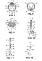
- Figure 7 shows a bottom view of the contact holder 3 with mounted contact assemblies 8. In this view is clearly the open circular arc shape of the contact holder 3 to recognize.
- a plate 24 is formed, starting from from the contact holder 3 in the inner region of the Contact holder 3 extends.
- the contact holder 3 On the outside of the contact holder 3 are sheet plates 26 arranged over the webs 27 with the contact holder. 3 are connected. Depending on the thickness of the webs 27 and the Width of the sheet plates 26 are the sheet plates 26 more or less resiliently attached to the contact holder 3. The lateral ends of the sheet plates 26 can be in the direction on the contact holder 3 due to the intervening Distance to bend.
- the contact holder 3 with the webs 27th and the sheet plates 26 are preferably made of plastic.
- the two opposite ends of the arcuate Contact holder 3 have outward extensions 28, which are led to the outer line, by the Arc shape of the adjacent sheet plates 26 given is.
- the arc plate 26 could also be on the inside of the Arch of the contact holder 3 may be arranged.
- the outer contour of the contact holder 3 is flexible educated.
- the flexible design of the contact holder 3 offers the advantage of having the desired press session made reliable between the housing 1 and the component 2 becomes.
- a shaving of chips avoided, which is a cleaning process would require.
- Figure 8 shows the contact holder 3 from above, so that the Openings 18 of the shafts 15 and the insertion funnel 12 of Plate 24 are clearly visible.
- the plate 24 offers a Support surface for the component 2.
- FIG. 9 shows a partial section of the plate 24 from below, the shafts 15, the slots 17, the openings 18, the Justierkanten 19, the insertion funnel 12 and the side walls 20 can be seen in an enlarged view.
- guide recesses 29 are introduced.
- FIG. 10 shows a perspective view of a Contact arrangement 8.
- the contact arrangement 8 points in a lower Connection area a contact surface 13.
- retaining tabs 30 are provided, the are formed bendable and for holding the contact pin 6 are used in laser welding. Will the weld manufactured via resistance welding, can on the Retaining tabs 30 are dispensed with.
- Above the retaining tabs 30 adjusting tabs 31 are arranged to guide the Contact arrangement 8 provided in the guide recesses 29 are.
- a resilient intermediate region 16 which is preferably formed as an S-shaped spring.
- the S-shape is substantially perpendicular to the orientation arranged the contact surface 13.
- the intermediate region 16 has a central recess 23.
- the intermediate area 16 goes in an intermediate piece 33 via, which is substantially parallel, but spaced from the contact surface 13 is formed.
- the Recess 23 extends from the plane of the contact surface 13 up to the level of the intermediate piece 33.
- the Adapter 33 is designed as a flat surface, which is extends upward and merges into a first bend 34.
- the intermediate piece 33, a locking lance 35, which starts from the intermediate piece 33 and in the direction of the contact surface 13 from the intermediate piece 33 is led out.
- the first bend 34 goes from the intermediate piece 33 and opens into a first insulation displacement contact 14.
- the first insulation displacement contact 14 is essentially formed as a flat plate having a central contact slot 37 has.
- the contact slot 37 expands into Direction of the first bend 34, leaving an insertion opening 38 is formed.
- the first bend 34 is starting from the intermediate piece 33 to the front, i. away from the contact surface 13 directed.
- the first insulation displacement contact 14 tapers in the upper area over a shoulder 39 to a smaller one Cross-section.
- the tapered insulation displacement contact 14 goes via a second bend 40 in a second insulation displacement contact 36 over.
- the second bend has a 180 ° radius.
- the second insulation displacement contact 36 is substantially symmetrical formed to the first insulation displacement contact 14 and parallel to the first insulation displacement contact 14 behind the first Insulation displacement contact 14 is arranged.
- the contact arrangement 8 only has a first one Insulation displacement contact 14.
- the arrangement of the second Insulation displacement contact 36 provides a safe and reliable Contacting the first pin 5.
- the second Insulation displacement contact 36 has a correspondingly shaped insertion opening 38 and a correspondingly shaped contact slot 37 on.
- the resilient intermediate portion 16 may, depending on the embodiment also essentially parallel and aligned to the intermediate piece 33 are arranged. However, experiments have shown that the vertical arrangement of the S-shaped intermediate portion 16 in With respect to the parallel planes of the contact surface 13 and the Insulation displacement contacts 14, 36 particularly high elastic properties causes and thereby improves the long-term stability becomes.
- the assembly tool 10 ( Figure 3) is substantially in shape a sleeve constructed on the contact holder 3 at Insert the contact holder 3 in the bore 7 of the housing 1 at least 3 distributed over the circumference of the arc Bearing surfaces rests.
- the component 2 is first inserted into the contact holder 3, then be the contact pin 6 and the contact surface 13 in the bottom Area welded together.
- a following process step becomes the preassembled unit of component 2 and contact holder 3 inserted with contact assembly 8 in the bore 7.
- the electrical connection 9 already connected to the housing 1 and the pins 5 protrude laterally into the hole 7.
- the housing 1 has a corresponding depression on the floor the bore 7 ( Figure 1).
- insulation displacement contact 14 also another contact surface for welding the connecting pin 5 be provided. Also, instead of the contact surface 13 may be provided an insulation displacement contact.
- the contact arrangement 8 is in a simple embodiment made of a stamped part, as shown in Figure 11 is. In this illustration, the one-piece embodiment the contact assembly 8 with the first and the second IDC contact 14, 36 clearly visible.
- FIG. 12 shows the contact arrangement 8, which consists of the stamped part 11 has been formed. It is clearly the S-shape of the resilient intermediate portion 16, the locking lance 35 and the parallel Arrangement of the first and second insulation displacement contact 36, 41 to recognize.
- FIG. 13 shows the contact arrangement 8 from the front.
- FIG. 14 shows a cross section through the contact arrangement 8, in which from above on the retaining tabs 30 and adjusting straps 31 is seen. Schematically, a contact pin 6th represented by the retaining tabs 30 against the contact surface 13 is held.
- Figure 15 shows the contact assembly 8 from below, the Recess 23, which is formed in the intermediate region 16, is clearly visible.
- FIG. 16 shows a partial section of a contact holder with contact assembly 8, via the welded joint 4 with a contact pin 6 is connected.
- the welded joint is formed between the contact pin 6 and the contact surface 13.
- the contact pin 6 and the contact surface 13 dimensioned so long that one with the contact surface 13 welded contact pin 6 cut off, the component 2 removed from the contact holder, repaired, then the component 2 is inserted back into the contact holder 3, and the cut contact pin 6 with the cut off Contact surface 13 can be welded again.
- FIG. 17 shows a detailed view of a mounted contact arrangement 8 in the contact holder 3, wherein the locking lance 35th engages in a latching step 42 of the contact holder 3.
- the locking lance 35th engages in a latching step 42 of the contact holder 3.
- At rest has the end of the locking lance 35 a fixed Distance from the edge of the latching step 42. This will be the Deflection of the contact assembly 8 down through the locking lance 35 limited to a maximum Auslenkungshub.
- the maximum Displacement stroke is determined by the distance between the Latch 35 and the latching level 42 set.
- FIG. 18 shows a section from the upper end region of FIG IDC arrangement.
- the shoulder 39 of the first and of the second insulation displacement contact 14, 36 is in a predetermined Distance to an associated second shoulder 43 of the Shaft 15 spaced.
- the Assembly tool 10 shown in the assembly both flush on the contact holder 3 as well as flush with the upper End of the contact assembly 8 is applied.
- the upper end of the contact assembly. 8 represented by the second bend 40.
- the second bend 40 protrudes through the opening 18 of the shaft 15 and is located on the assembly tool 10.
- a defined Distance between the shoulder 39 of the contact arrangement and the second shoulder 43 of the contact holder set. This is a maximum deflection of the contact assembly. 8 set up.
- the second insulation displacement contact 36 is a corresponding Shoulder 39 on.
- the contact holder preferably has a shaft 15, which is open at the top, so that when mounting an upper End portion of the insulation displacement contact 14, 36 on a mounting tool 10 is applied and the contact assembly 8 of the assembly tool 10 during assembly of the contact holder 3 in a housing 1 adjustable with respect to the position in the contact holder is.
- the contact arrangement 8 preferably has an outward-facing Latch 35 on which a latching step 42 of the contact holder 3 is assigned, wherein the locking lance 35 a maximum deflection of the contact arrangement in one direction limited by a system in the latching level 42.
- an upper end portion of the insulation displacement contact 14, 36 of the contact holder up to a smaller Width cut and the incision 39 of the insulation displacement contact 14, 36 is a tapered edge 43 of the Chute 15 assigned, wherein by conditioning of the incision 39 at the Verjüngungskante 43 a maximum deflection of the Contact arrangement 8 is given upwards.
Landscapes
- Connector Housings Or Holding Contact Members (AREA)
- Coupling Device And Connection With Printed Circuit (AREA)
- Multi-Conductor Connections (AREA)
Abstract
Description
- 1
- Gehäuse
- 2
- elektrisches Bauteil
- 3
- Kontakthalterung
- 4
- Schweissverbindung
- 5
- Anschlussstift
- 6
- Kontaktstift
- 7
- Bohrung
- 8
- Kontaktanordnung
- 9
- elektrischer Anschluss
- 10
- Montagewerkzeug
- 11
- Seitenwand
- 12
- Einführtrichter
- 13
- Anlagefläche
- 14
- Schneidklemmkontakt
- 15
- Schacht
- 16
- S-förmige Feder
- 17
- Schlitz
- 18
- Öffnung
- 19
- Justierkante
- 20
- Bogen
- 21
- Aufnahmeraum
- 22
- Haltearme
- 23
- Ausnehmung
- 24
- Platte
- 25
- Kontaktbereich
- 26
- Bogenplatte
- 27
- Steg
- 28
- Fortsatz
- 29
- Führungsausnehmung
- 30
- Haltelasche
- 31
- Justierlasche
- 33
- Zwischenstück
- 34
- Erste Biegung
- 35
- Rastlanze
- 36
- zweiter Schneidklemmkontakt
- 37
- Kontaktschlitz
- 38
- Einschuböffnung
- 39
- Schulter
- 40
- Zweite Biegung
- 42
- Raststufe
- 43
- zweite Schulter
Claims (12)
- Elektrische Kontaktanordnung (8) mit einem ersten und einem zweiten Anschlussbereich, wobei die zwei Anschlussbereiche über einen federnden Zwischenbereich (16) miteinander in Verbindung stehen, wobei der erste Anschlussbereich (14, 36) zur Kontaktierung eines ersten Kontaktes (5) und der zweite Anschlussbereich (13) zur Kontaktierung eines zweiten Kontaktes (6) vorgesehen ist,
dadurch gekennzeichnet, dass der erste und zweite Anschlussbereich (14, 36, 13) seitlich versetzt und übereinander angeordnet sind,
dass der Zwischenbereich (16) von dem zweiten Anschlussbereich (13) ausgeht und mindestens teilweise seitlich von dem zweiten Anschlussbereich (13) weggerichtet ist,
dass der Zwischenbereich (16) angrenzend an den zweiten Anschlussbereich (13) eine Ausnehmung (23) aufweist und
dass die Ausnehmung (23) zur Durchführung des zweiten Kontaktes (6) vorgesehen ist. - Elektrische Kontaktanordnung nach Anspruch 1, dadurch gekennzeichnet, dass der zweite Anschlussbereich als Anlagefläche (13) und der erste Anschlussbereich als Schneidklemmkontakt (14, 36) ausgebildet sind, dass der Schneidklemmkontakt (14, 36) eine Einschuböffnung (38) für den ersten Kontakt aufweist und dass die Einschuböffnung (38) durch eine Biegung (34) des Schneidklemmkontaktes (14, 36) im unteren Bereich eines Schlitzes (37) gebildet ist.
- Elektrische Kontaktanordnung nach einem der Ansprüche 1 oder 2, dadurch gekennzeichnet, dass als erster Anschlussbereich zwei Schneidklemmkontakte (14, 36) angeordnet sind, dass die zwei Schneidklemmkontakte (14, 36) einstückig ausgebildet und über eine Umbiegung (40) miteinander verbunden sind.
- Elektrische Kontaktanordnung nach einem der Ansprüche 1 bis 3, dadurch gekennzeichnet, dass der federnde Zwischenbereich (16) als S-förmige Feder ausgebildet ist, und dass die S-Form nahezu senkrecht zur Anlagefläche (13) angeordnet ist.
- Elektrische Kontaktanordnung nach einem der Ansprüche 2 bis 4, dadurch gekennzeichnet, dass die Anlagefläche (13) seitlich angeformte und biegbare Haltelaschen (30) aufweist, mit denen der zweite Kontakt (6) formschlüssig an der Anlagefläche (13) halterbar ist.
- Elektrische Kontaktanordnung nach einem der Ansprüche 1 bis 5, dadurch gekennzeichnet, dass die elektrische Kontaktanordnung (8) als einstückiges Stanzteil ausgebildet ist, das nach dem Stanzvorgang in die gewünschte Form gebogen wurde.
- Kontakthalterung (3) mit einer elektrischen Kontaktanordnung (8), wobei die Kontaktanordnung (8) einen ersten und einen zweiten Anschlussbereich (13, 14) zum Kontaktieren von zwei Kontakten (5, 6) aufweist, wobei ein Kontakt (6) mit einem elektrischen Bauteil (2) fest verbunden ist,
dadurch gekennzeichnet, dass die Kontakthalterung (3) in Form eines flexiblen Bogens (20) ausgebildet ist, und dass der Bogen das Bauteil (2) mindestens teilweise umfasst. - Kontakthalterung nach Anspruch 7, dadurch gekennzeichnet, dass der Bogen Federelemente (26) aufweist und dass die Federelemente (26) auf der Außen- oder Innenseite des Bogens (20) ausgebildet sind.
- Kontakthalterung nach einem der Ansprüche 7 oder 8, dadurch gekennzeichnet, dass die Federelemente in Form von Bogenplatten (26) ausgebildet sind, die über einen Steg (27) am Bogen (20) federnd gehaltert sind.
- Kontakthalterung nach einem der Ansprüche 7 bis 9, dadurch gekennzeichnet, dass an einer Unterseite des Bogens (20) eine Platte (24) ausgebildet ist, dass die Platte (24) in einen vom Bogen (20) begrenzten Innenbereich ragt, dass die Platte (24) eine Durchführung (12) für den Kontakt (6) des elektrischen Bauteils (2) aufweist, und dass angrenzend an die Platte (24) die Kontaktanordnung (8) angeordnet ist, um einen Kontakt zwischen der Kontaktanordnung (8) und dem Kontakt (6) des elektrischen Bauteils (2) zu ermöglichen.
- Kontakthalterung nach Anspruch 10, dadurch gekennzeichnet, dass der Bogen (20) zwei Haltearme (22) aufweist, die von dem Kontaktbereich beabstandet sind und von einem niedrigeren Bogenbereich ausgehen, dass die Haltearme (22) im wesentlichen senkrecht zu dem Bogen (20) ausgerichtet sind, und dass die Haltearme (22) im wesentlichen bis zur Höhe des Kontaktbereichs geführt sind.
- Kontakthalterung mit einer elektrischen Kontaktanordnung gemäß Anspruch 2,
dadurch gekennzeichnet, dass die Kontakthalterung einen von unten offenen Schacht (15) aufweist, in den als erster Anschlussbereich ein Schneidklemmkontakt (14, 36) eingeschoben ist,
dass der Schacht (15) auf einer Außenseite einen von unten offenen Schlitz (17) aufweist, dass der Schlitz (17) des Schachtes (15) vor einem Kontaktschlitz (37) des Schneidklemmkontaktes (14, 36) angeordnet ist,
dass ein von unten offener Aufnahmeraum (21) vorgesehen ist, dass der Aufnahmeraum (21) weiter in Richtung Bogenmitte und tiefer als der Schacht (15) angeordnet ist,
dass als zweiter Anschlussbereich eine Anlagefläche (13) in dem Aufnahmeraum (21) angeordnet ist,
dass zwischen dem Aufnahmeraum (21) und dem Schacht (15) eine Kontaktdurchführung (12) ausgebildet ist, die oberhalb der Ausnehmung (23) des Zwischenbereichs (16) angeordnet ist, und dass der Zwischenbereich (16) teilweise zwischen dem Aufnahmeraum (21) und dem Schacht (15) angeordnet ist.
Priority Applications (1)
| Application Number | Priority Date | Filing Date | Title |
|---|---|---|---|
| EP20030024979 EP1418647B1 (de) | 2002-11-07 | 2003-10-29 | Elektrische Kontaktanordnung und Kontakthalterung mit einer elektrischen Kontaktanordnung |
Applications Claiming Priority (3)
| Application Number | Priority Date | Filing Date | Title |
|---|---|---|---|
| EP02024837 | 2002-11-07 | ||
| EP02024837 | 2002-11-07 | ||
| EP20030024979 EP1418647B1 (de) | 2002-11-07 | 2003-10-29 | Elektrische Kontaktanordnung und Kontakthalterung mit einer elektrischen Kontaktanordnung |
Publications (3)
| Publication Number | Publication Date |
|---|---|
| EP1418647A2 true EP1418647A2 (de) | 2004-05-12 |
| EP1418647A3 EP1418647A3 (de) | 2005-01-12 |
| EP1418647B1 EP1418647B1 (de) | 2007-01-24 |
Family
ID=32109138
Family Applications (1)
| Application Number | Title | Priority Date | Filing Date |
|---|---|---|---|
| EP20030024979 Expired - Lifetime EP1418647B1 (de) | 2002-11-07 | 2003-10-29 | Elektrische Kontaktanordnung und Kontakthalterung mit einer elektrischen Kontaktanordnung |
Country Status (1)
| Country | Link |
|---|---|
| EP (1) | EP1418647B1 (de) |
Cited By (1)
| Publication number | Priority date | Publication date | Assignee | Title |
|---|---|---|---|---|
| DE102018210425A1 (de) * | 2018-06-26 | 2020-01-02 | Brose Fahrzeugteile Gmbh & Co. Kommanditgesellschaft, Bamberg | Nebenaggregat eines Kraftfahrzeugs |
Family Cites Families (3)
| Publication number | Priority date | Publication date | Assignee | Title |
|---|---|---|---|---|
| DE2603151C3 (de) * | 1976-01-28 | 1978-10-26 | Siemens Ag, 1000 Berlin Und 8000 Muenchen | Bauelement für Schalt- und/oder Trennleisten in Verteilern für Fernmeldeanlagen |
| US4322647A (en) * | 1979-11-23 | 1982-03-30 | The Scott & Fetzer Company | Motor assembly |
| DE19735945A1 (de) * | 1997-08-19 | 1999-02-25 | Friedrich Dipl Ing Kourimsky | Elektrischer Kontakt in Edelstahl auf Basis Schneid-Klemmtechnik |
-
2003
- 2003-10-29 EP EP20030024979 patent/EP1418647B1/de not_active Expired - Lifetime
Cited By (1)
| Publication number | Priority date | Publication date | Assignee | Title |
|---|---|---|---|---|
| DE102018210425A1 (de) * | 2018-06-26 | 2020-01-02 | Brose Fahrzeugteile Gmbh & Co. Kommanditgesellschaft, Bamberg | Nebenaggregat eines Kraftfahrzeugs |
Also Published As
| Publication number | Publication date |
|---|---|
| EP1418647B1 (de) | 2007-01-24 |
| EP1418647A3 (de) | 2005-01-12 |
Similar Documents
| Publication | Publication Date | Title |
|---|---|---|
| DE69306463T2 (de) | Elektrischer Flachbauverbinder | |
| EP3507866B1 (de) | Leiteranschlussklemme | |
| EP1429423B1 (de) | Elektrische Steckverbindung mit einem Gehäuse und einem Hochstromkontakt | |
| EP1680840B1 (de) | Flachsteckbuchse | |
| DE69415092T2 (de) | Lötfreie Steckverrieglung für eine Leiterplatte | |
| DE102005033696B4 (de) | Kontaktelement | |
| EP2561582B1 (de) | Elektrischer steckkontakt | |
| EP1215763B2 (de) | Kontaktbuchse für eine elektrische Steckverbindung | |
| WO1998013898A1 (de) | Kontaktorgan mit doppel-schneidklemmanschluss | |
| DE102005057211B4 (de) | Elektrisches Kontaktelement und Kontaktanordnung | |
| EP1587172B1 (de) | Steckbuchse zum elektrisch leitenden Verbinden mit einem Steckstift, insbesondere Flachsteckstift | |
| DE10134380B4 (de) | Gehäuse mit darin untergebrachter elektrischer Schaltung | |
| EP1418647B1 (de) | Elektrische Kontaktanordnung und Kontakthalterung mit einer elektrischen Kontaktanordnung | |
| EP4292173B1 (de) | Einsatz für einen verbinder | |
| EP1248318B1 (de) | Elektrischer Kontakt sowie Lampenfassung und Anschluss- oder Verbindungsklemme mit mindestens einem solchen Kontakt | |
| DE10331034B4 (de) | Kontaktbuchse | |
| DE19648277B4 (de) | Elektrische Anschlußklemme | |
| DE10227235A1 (de) | Leiteranschluss | |
| DE102006006484A1 (de) | Steckerteil und Buchsenteil für eine elektrische Steckverbindung und elektrische Steckverbindungs-Anordnung mit einem solchen Steckerteil und Buchsenteil | |
| EP1455421A1 (de) | Stecker mit Drehring mit einrastbarem Halteelement | |
| BE1032383B1 (de) | Halterahmen für einen Steckverbinder | |
| DE10261733A1 (de) | Steckverbinder mit gerollter Hülse | |
| DE102020110176B4 (de) | Elektrische Kontaktvorrichtung für einen elektrischen Verbinder und Verbinder | |
| EP1974417A1 (de) | Vorrichtung zum anschluss eines stegs | |
| DE3932346A1 (de) | Elektrischer steckverbinder |
Legal Events
| Date | Code | Title | Description |
|---|---|---|---|
| PUAI | Public reference made under article 153(3) epc to a published international application that has entered the european phase |
Free format text: ORIGINAL CODE: 0009012 |
|
| AK | Designated contracting states |
Kind code of ref document: A2 Designated state(s): AT BE BG CH CY CZ DE DK EE ES FI FR GB GR HU IE IT LI LU MC NL PT RO SE SI SK TR |
|
| AX | Request for extension of the european patent |
Extension state: AL LT LV MK |
|
| PUAL | Search report despatched |
Free format text: ORIGINAL CODE: 0009013 |
|
| AK | Designated contracting states |
Kind code of ref document: A3 Designated state(s): AT BE BG CH CY CZ DE DK EE ES FI FR GB GR HU IE IT LI LU MC NL PT RO SE SI SK TR |
|
| AX | Request for extension of the european patent |
Extension state: AL LT LV MK |
|
| 17P | Request for examination filed |
Effective date: 20050705 |
|
| AKX | Designation fees paid |
Designated state(s): AT BE BG CH CY CZ DE DK EE ES FI FR GB GR HU IE IT LI LU MC NL PT RO SE SI SK TR |
|
| GRAP | Despatch of communication of intention to grant a patent |
Free format text: ORIGINAL CODE: EPIDOSNIGR1 |
|
| GRAS | Grant fee paid |
Free format text: ORIGINAL CODE: EPIDOSNIGR3 |
|
| GRAA | (expected) grant |
Free format text: ORIGINAL CODE: 0009210 |
|
| AK | Designated contracting states |
Kind code of ref document: B1 Designated state(s): AT BE BG CH CY CZ DE DK EE ES FI FR GB GR HU IE IT LI LU MC NL PT RO SE SI SK TR |
|
| PG25 | Lapsed in a contracting state [announced via postgrant information from national office to epo] |
Ref country code: IE Free format text: LAPSE BECAUSE OF FAILURE TO SUBMIT A TRANSLATION OF THE DESCRIPTION OR TO PAY THE FEE WITHIN THE PRESCRIBED TIME-LIMIT Effective date: 20070124 Ref country code: SI Free format text: LAPSE BECAUSE OF FAILURE TO SUBMIT A TRANSLATION OF THE DESCRIPTION OR TO PAY THE FEE WITHIN THE PRESCRIBED TIME-LIMIT Effective date: 20070124 Ref country code: NL Free format text: LAPSE BECAUSE OF FAILURE TO SUBMIT A TRANSLATION OF THE DESCRIPTION OR TO PAY THE FEE WITHIN THE PRESCRIBED TIME-LIMIT Effective date: 20070124 Ref country code: FI Free format text: LAPSE BECAUSE OF FAILURE TO SUBMIT A TRANSLATION OF THE DESCRIPTION OR TO PAY THE FEE WITHIN THE PRESCRIBED TIME-LIMIT Effective date: 20070124 Ref country code: DK Free format text: LAPSE BECAUSE OF FAILURE TO SUBMIT A TRANSLATION OF THE DESCRIPTION OR TO PAY THE FEE WITHIN THE PRESCRIBED TIME-LIMIT Effective date: 20070124 |
|
| REG | Reference to a national code |
Ref country code: GB Ref legal event code: FG4D Free format text: NOT ENGLISH |
|
| REG | Reference to a national code |
Ref country code: CH Ref legal event code: EP |
|
| REG | Reference to a national code |
Ref country code: IE Ref legal event code: FG4D Free format text: LANGUAGE OF EP DOCUMENT: GERMAN |
|
| REF | Corresponds to: |
Ref document number: 50306363 Country of ref document: DE Date of ref document: 20070315 Kind code of ref document: P |
|
| PG25 | Lapsed in a contracting state [announced via postgrant information from national office to epo] |
Ref country code: SE Free format text: LAPSE BECAUSE OF FAILURE TO SUBMIT A TRANSLATION OF THE DESCRIPTION OR TO PAY THE FEE WITHIN THE PRESCRIBED TIME-LIMIT Effective date: 20070424 |
|
| PG25 | Lapsed in a contracting state [announced via postgrant information from national office to epo] |
Ref country code: BG Free format text: LAPSE BECAUSE OF EXPIRATION OF PROTECTION Effective date: 20070425 |
|
| PG25 | Lapsed in a contracting state [announced via postgrant information from national office to epo] |
Ref country code: ES Free format text: LAPSE BECAUSE OF FAILURE TO SUBMIT A TRANSLATION OF THE DESCRIPTION OR TO PAY THE FEE WITHIN THE PRESCRIBED TIME-LIMIT Effective date: 20070505 |
|
| GBT | Gb: translation of ep patent filed (gb section 77(6)(a)/1977) |
Effective date: 20070424 |
|
| PG25 | Lapsed in a contracting state [announced via postgrant information from national office to epo] |
Ref country code: PT Free format text: LAPSE BECAUSE OF FAILURE TO SUBMIT A TRANSLATION OF THE DESCRIPTION OR TO PAY THE FEE WITHIN THE PRESCRIBED TIME-LIMIT Effective date: 20070625 |
|
| NLV1 | Nl: lapsed or annulled due to failure to fulfill the requirements of art. 29p and 29m of the patents act | ||
| ET | Fr: translation filed | ||
| REG | Reference to a national code |
Ref country code: IE Ref legal event code: FD4D |
|
| PG25 | Lapsed in a contracting state [announced via postgrant information from national office to epo] |
Ref country code: SK Free format text: LAPSE BECAUSE OF FAILURE TO SUBMIT A TRANSLATION OF THE DESCRIPTION OR TO PAY THE FEE WITHIN THE PRESCRIBED TIME-LIMIT Effective date: 20070124 |
|
| PLBE | No opposition filed within time limit |
Free format text: ORIGINAL CODE: 0009261 |
|
| STAA | Information on the status of an ep patent application or granted ep patent |
Free format text: STATUS: NO OPPOSITION FILED WITHIN TIME LIMIT |
|
| 26N | No opposition filed |
Effective date: 20071025 |
|
| PG25 | Lapsed in a contracting state [announced via postgrant information from national office to epo] |
Ref country code: RO Free format text: LAPSE BECAUSE OF FAILURE TO SUBMIT A TRANSLATION OF THE DESCRIPTION OR TO PAY THE FEE WITHIN THE PRESCRIBED TIME-LIMIT Effective date: 20070124 |
|
| BERE | Be: lapsed |
Owner name: TYCO ELECTRONICS AMP G.M.B.H. Effective date: 20071031 |
|
| PG25 | Lapsed in a contracting state [announced via postgrant information from national office to epo] |
Ref country code: IT Free format text: LAPSE BECAUSE OF FAILURE TO SUBMIT A TRANSLATION OF THE DESCRIPTION OR TO PAY THE FEE WITHIN THE PRESCRIBED TIME-LIMIT Effective date: 20070124 Ref country code: GR Free format text: LAPSE BECAUSE OF FAILURE TO SUBMIT A TRANSLATION OF THE DESCRIPTION OR TO PAY THE FEE WITHIN THE PRESCRIBED TIME-LIMIT Effective date: 20070425 |
|
| PG25 | Lapsed in a contracting state [announced via postgrant information from national office to epo] |
Ref country code: MC Free format text: LAPSE BECAUSE OF NON-PAYMENT OF DUE FEES Effective date: 20071031 |
|
| REG | Reference to a national code |
Ref country code: CH Ref legal event code: PL |
|
| PG25 | Lapsed in a contracting state [announced via postgrant information from national office to epo] |
Ref country code: LI Free format text: LAPSE BECAUSE OF NON-PAYMENT OF DUE FEES Effective date: 20071031 Ref country code: CH Free format text: LAPSE BECAUSE OF NON-PAYMENT OF DUE FEES Effective date: 20071031 |
|
| PG25 | Lapsed in a contracting state [announced via postgrant information from national office to epo] |
Ref country code: BE Free format text: LAPSE BECAUSE OF NON-PAYMENT OF DUE FEES Effective date: 20071031 |
|
| PG25 | Lapsed in a contracting state [announced via postgrant information from national office to epo] |
Ref country code: EE Free format text: LAPSE BECAUSE OF FAILURE TO SUBMIT A TRANSLATION OF THE DESCRIPTION OR TO PAY THE FEE WITHIN THE PRESCRIBED TIME-LIMIT Effective date: 20070124 |
|
| PG25 | Lapsed in a contracting state [announced via postgrant information from national office to epo] |
Ref country code: AT Free format text: LAPSE BECAUSE OF NON-PAYMENT OF DUE FEES Effective date: 20071029 |
|
| PG25 | Lapsed in a contracting state [announced via postgrant information from national office to epo] |
Ref country code: CY Free format text: LAPSE BECAUSE OF FAILURE TO SUBMIT A TRANSLATION OF THE DESCRIPTION OR TO PAY THE FEE WITHIN THE PRESCRIBED TIME-LIMIT Effective date: 20070124 |
|
| PG25 | Lapsed in a contracting state [announced via postgrant information from national office to epo] |
Ref country code: LU Free format text: LAPSE BECAUSE OF NON-PAYMENT OF DUE FEES Effective date: 20071029 |
|
| PG25 | Lapsed in a contracting state [announced via postgrant information from national office to epo] |
Ref country code: HU Free format text: LAPSE BECAUSE OF FAILURE TO SUBMIT A TRANSLATION OF THE DESCRIPTION OR TO PAY THE FEE WITHIN THE PRESCRIBED TIME-LIMIT Effective date: 20070725 Ref country code: TR Free format text: LAPSE BECAUSE OF FAILURE TO SUBMIT A TRANSLATION OF THE DESCRIPTION OR TO PAY THE FEE WITHIN THE PRESCRIBED TIME-LIMIT Effective date: 20070124 |
|
| REG | Reference to a national code |
Ref country code: DE Ref legal event code: R082 Ref document number: 50306363 Country of ref document: DE Representative=s name: WILHELM & BECK, DE Ref country code: DE Ref legal event code: R081 Ref document number: 50306363 Country of ref document: DE Owner name: TE CONNECTIVITY GERMANY GMBH, DE Free format text: FORMER OWNER: TYCO ELECTRONICS AMP GMBH, 64625 BENSHEIM, DE |
|
| REG | Reference to a national code |
Ref country code: FR Ref legal event code: PLFP Year of fee payment: 13 |
|
| REG | Reference to a national code |
Ref country code: FR Ref legal event code: CD Owner name: TE CONNECTIVITY GERMANY GMBH Effective date: 20151027 |
|
| REG | Reference to a national code |
Ref country code: FR Ref legal event code: PLFP Year of fee payment: 14 |
|
| REG | Reference to a national code |
Ref country code: FR Ref legal event code: PLFP Year of fee payment: 15 |
|
| REG | Reference to a national code |
Ref country code: FR Ref legal event code: PLFP Year of fee payment: 16 |
|
| PGFP | Annual fee paid to national office [announced via postgrant information from national office to epo] |
Ref country code: FR Payment date: 20190913 Year of fee payment: 17 |
|
| PGFP | Annual fee paid to national office [announced via postgrant information from national office to epo] |
Ref country code: DE Payment date: 20191015 Year of fee payment: 17 Ref country code: CZ Payment date: 20191024 Year of fee payment: 17 |
|
| PGFP | Annual fee paid to national office [announced via postgrant information from national office to epo] |
Ref country code: GB Payment date: 20191024 Year of fee payment: 17 |
|
| REG | Reference to a national code |
Ref country code: DE Ref legal event code: R119 Ref document number: 50306363 Country of ref document: DE |
|
| GBPC | Gb: european patent ceased through non-payment of renewal fee |
Effective date: 20201029 |
|
| PG25 | Lapsed in a contracting state [announced via postgrant information from national office to epo] |
Ref country code: DE Free format text: LAPSE BECAUSE OF NON-PAYMENT OF DUE FEES Effective date: 20210501 Ref country code: CZ Free format text: LAPSE BECAUSE OF NON-PAYMENT OF DUE FEES Effective date: 20201029 Ref country code: FR Free format text: LAPSE BECAUSE OF NON-PAYMENT OF DUE FEES Effective date: 20201031 |
|
| PG25 | Lapsed in a contracting state [announced via postgrant information from national office to epo] |
Ref country code: GB Free format text: LAPSE BECAUSE OF NON-PAYMENT OF DUE FEES Effective date: 20201029 |