EP1418362A2 - Verfahren und Vorrichtung zum Positionieren eines Stösselstangkopfes eines Bremsaktuators - Google Patents
Verfahren und Vorrichtung zum Positionieren eines Stösselstangkopfes eines Bremsaktuators Download PDFInfo
- Publication number
- EP1418362A2 EP1418362A2 EP03025214A EP03025214A EP1418362A2 EP 1418362 A2 EP1418362 A2 EP 1418362A2 EP 03025214 A EP03025214 A EP 03025214A EP 03025214 A EP03025214 A EP 03025214A EP 1418362 A2 EP1418362 A2 EP 1418362A2
- Authority
- EP
- European Patent Office
- Prior art keywords
- push rod
- ball end
- transfer member
- force transfer
- relative
- Prior art date
- Legal status (The legal status is an assumption and is not a legal conclusion. Google has not performed a legal analysis and makes no representation as to the accuracy of the status listed.)
- Granted
Links
- 238000000034 method Methods 0.000 title claims abstract description 36
- 230000009969 flowable effect Effects 0.000 claims abstract description 12
- 239000000654 additive Substances 0.000 claims description 12
- 230000000996 additive effect Effects 0.000 claims description 12
- 238000007711 solidification Methods 0.000 claims description 6
- 230000008023 solidification Effects 0.000 claims description 6
- 230000008878 coupling Effects 0.000 claims 1
- 238000010168 coupling process Methods 0.000 claims 1
- 238000005859 coupling reaction Methods 0.000 claims 1
- 230000008901 benefit Effects 0.000 description 8
- 230000001419 dependent effect Effects 0.000 description 3
- 239000007788 liquid Substances 0.000 description 3
- 239000007787 solid Substances 0.000 description 3
- 150000001875 compounds Chemical class 0.000 description 2
- 229910000078 germane Inorganic materials 0.000 description 2
- 238000002347 injection Methods 0.000 description 2
- 239000007924 injection Substances 0.000 description 2
- 239000000463 material Substances 0.000 description 2
- 239000000843 powder Substances 0.000 description 2
- 125000006850 spacer group Chemical group 0.000 description 2
- 230000000007 visual effect Effects 0.000 description 2
- HCHKCACWOHOZIP-UHFFFAOYSA-N Zinc Chemical compound [Zn] HCHKCACWOHOZIP-UHFFFAOYSA-N 0.000 description 1
- 229910001297 Zn alloy Inorganic materials 0.000 description 1
- 239000000853 adhesive Substances 0.000 description 1
- 230000001070 adhesive effect Effects 0.000 description 1
- 238000003780 insertion Methods 0.000 description 1
- 230000037431 insertion Effects 0.000 description 1
- 238000012986 modification Methods 0.000 description 1
- 230000004048 modification Effects 0.000 description 1
- 230000002028 premature Effects 0.000 description 1
- 230000002035 prolonged effect Effects 0.000 description 1
- 239000011343 solid material Substances 0.000 description 1
- 239000000243 solution Substances 0.000 description 1
- 239000011701 zinc Substances 0.000 description 1
- 229910052725 zinc Inorganic materials 0.000 description 1
Images



Classifications
-
- B—PERFORMING OPERATIONS; TRANSPORTING
- B60—VEHICLES IN GENERAL
- B60T—VEHICLE BRAKE CONTROL SYSTEMS OR PARTS THEREOF; BRAKE CONTROL SYSTEMS OR PARTS THEREOF, IN GENERAL; ARRANGEMENT OF BRAKING ELEMENTS ON VEHICLES IN GENERAL; PORTABLE DEVICES FOR PREVENTING UNWANTED MOVEMENT OF VEHICLES; VEHICLE MODIFICATIONS TO FACILITATE COOLING OF BRAKES
- B60T17/00—Component parts, details, or accessories of power brake systems not covered by groups B60T8/00, B60T13/00 or B60T15/00, or presenting other characteristic features
- B60T17/08—Brake cylinders other than ultimate actuators
- B60T17/081—Single service brake actuators
-
- B—PERFORMING OPERATIONS; TRANSPORTING
- B60—VEHICLES IN GENERAL
- B60T—VEHICLE BRAKE CONTROL SYSTEMS OR PARTS THEREOF; BRAKE CONTROL SYSTEMS OR PARTS THEREOF, IN GENERAL; ARRANGEMENT OF BRAKING ELEMENTS ON VEHICLES IN GENERAL; PORTABLE DEVICES FOR PREVENTING UNWANTED MOVEMENT OF VEHICLES; VEHICLE MODIFICATIONS TO FACILITATE COOLING OF BRAKES
- B60T7/00—Brake-action initiating means
- B60T7/02—Brake-action initiating means for personal initiation
- B60T7/08—Brake-action initiating means for personal initiation hand actuated
- B60T7/10—Disposition of hand control
-
- B—PERFORMING OPERATIONS; TRANSPORTING
- B60—VEHICLES IN GENERAL
- B60T—VEHICLE BRAKE CONTROL SYSTEMS OR PARTS THEREOF; BRAKE CONTROL SYSTEMS OR PARTS THEREOF, IN GENERAL; ARRANGEMENT OF BRAKING ELEMENTS ON VEHICLES IN GENERAL; PORTABLE DEVICES FOR PREVENTING UNWANTED MOVEMENT OF VEHICLES; VEHICLE MODIFICATIONS TO FACILITATE COOLING OF BRAKES
- B60T17/00—Component parts, details, or accessories of power brake systems not covered by groups B60T8/00, B60T13/00 or B60T15/00, or presenting other characteristic features
- B60T17/08—Brake cylinders other than ultimate actuators
- B60T17/088—Mounting arrangements
-
- F—MECHANICAL ENGINEERING; LIGHTING; HEATING; WEAPONS; BLASTING
- F16—ENGINEERING ELEMENTS AND UNITS; GENERAL MEASURES FOR PRODUCING AND MAINTAINING EFFECTIVE FUNCTIONING OF MACHINES OR INSTALLATIONS; THERMAL INSULATION IN GENERAL
- F16D—COUPLINGS FOR TRANSMITTING ROTATION; CLUTCHES; BRAKES
- F16D65/00—Parts or details
- F16D65/14—Actuating mechanisms for brakes; Means for initiating operation at a predetermined position
- F16D65/16—Actuating mechanisms for brakes; Means for initiating operation at a predetermined position arranged in or on the brake
- F16D65/18—Actuating mechanisms for brakes; Means for initiating operation at a predetermined position arranged in or on the brake adapted for drawing members together, e.g. for disc brakes
-
- F—MECHANICAL ENGINEERING; LIGHTING; HEATING; WEAPONS; BLASTING
- F16—ENGINEERING ELEMENTS AND UNITS; GENERAL MEASURES FOR PRODUCING AND MAINTAINING EFFECTIVE FUNCTIONING OF MACHINES OR INSTALLATIONS; THERMAL INSULATION IN GENERAL
- F16D—COUPLINGS FOR TRANSMITTING ROTATION; CLUTCHES; BRAKES
- F16D65/00—Parts or details
- F16D65/14—Actuating mechanisms for brakes; Means for initiating operation at a predetermined position
- F16D65/28—Actuating mechanisms for brakes; Means for initiating operation at a predetermined position arranged apart from the brake
-
- F—MECHANICAL ENGINEERING; LIGHTING; HEATING; WEAPONS; BLASTING
- F16—ENGINEERING ELEMENTS AND UNITS; GENERAL MEASURES FOR PRODUCING AND MAINTAINING EFFECTIVE FUNCTIONING OF MACHINES OR INSTALLATIONS; THERMAL INSULATION IN GENERAL
- F16D—COUPLINGS FOR TRANSMITTING ROTATION; CLUTCHES; BRAKES
- F16D2121/00—Type of actuator operation force
- F16D2121/02—Fluid pressure
-
- F—MECHANICAL ENGINEERING; LIGHTING; HEATING; WEAPONS; BLASTING
- F16—ENGINEERING ELEMENTS AND UNITS; GENERAL MEASURES FOR PRODUCING AND MAINTAINING EFFECTIVE FUNCTIONING OF MACHINES OR INSTALLATIONS; THERMAL INSULATION IN GENERAL
- F16D—COUPLINGS FOR TRANSMITTING ROTATION; CLUTCHES; BRAKES
- F16D2125/00—Components of actuators
- F16D2125/18—Mechanical mechanisms
- F16D2125/20—Mechanical mechanisms converting rotation to linear movement or vice versa
- F16D2125/22—Mechanical mechanisms converting rotation to linear movement or vice versa acting transversely to the axis of rotation
- F16D2125/28—Cams; Levers with cams
- F16D2125/32—Cams; Levers with cams acting on one cam follower
-
- F—MECHANICAL ENGINEERING; LIGHTING; HEATING; WEAPONS; BLASTING
- F16—ENGINEERING ELEMENTS AND UNITS; GENERAL MEASURES FOR PRODUCING AND MAINTAINING EFFECTIVE FUNCTIONING OF MACHINES OR INSTALLATIONS; THERMAL INSULATION IN GENERAL
- F16D—COUPLINGS FOR TRANSMITTING ROTATION; CLUTCHES; BRAKES
- F16D2125/00—Components of actuators
- F16D2125/18—Mechanical mechanisms
- F16D2125/58—Mechanical mechanisms transmitting linear movement
- F16D2125/70—Rods
Definitions
- the invention relates to braking systems and, more particularly, a method and apparatus for positioning an end of a push rod of a brake actuator.
- Braking systems such as air brake systems
- air brakes are commonly used on commercial vehicles such as trucks, trailers, and buses, which typically have large gross vehicle weights.
- the considerable inertial mass of these heavy-duty vehicles in combination with the high speeds at which they travel often requires a braking system which responds rapidly with substantial braking power.
- One system component which may be instrumental in the operation of air brake systems is the brake actuator.
- the brake actuator typically provides the necessary force when braking the vehicle.
- FIG. 1 depicts a push rod generally known in the art.
- the push rod is a component of brake actuator 12 and is commonly found in many air disc brake systems.
- push rod 10 typically extends outwardly away from a mounting face 17 of brake actuator 12.
- the end of push rod 10 engages with ball end 16 of arm 14, typically a socket part of arm 14.
- the overall length L' of push rod 10 and ball end 16 relative to mounting face 17 is important to proper braking. Because of such importance, the overall length L' may be adjustable.
- Kohar U.S. Patent No. 5,579,873 to Kohar et al.
- Kohar may also use spacers to operate as shims in adjusting the calipers.
- the overall length of the push rod and ball end relative to a mounting face surface of the actuator is usually essential to proper functioning of the brake system. If this length is too short, a user may need to apply the brakes in a more vigorous manner to brake the vehicle than if the overall length was properly determined. If the overall length is too long, the brakes may be applied continuously or when a user does not wish the vehicle to be braked, which may cause premature wear on the brakes. Because of the importance of the overall length, using shims to variably adjust the overall length may negatively affect accurate determinations of this length, which may possibly affect braking performance.
- the overall length is determined within an acceptable tolerance range.
- the components that make up the overall length namely the push rod, ball end, and any shims used, are also typically manufactured within a known tolerance range. Combining the components typically results in the combination of the tolerances of the individual components to determine the overall tolerance range. This combination of the tolerances is known in the art to be defined as a "tolerance stack up". The more shims used, the larger the overall tolerance range may become. In some instances, especially where an accurate determination of the overall length is desired, the resulting tolerance stack up may be larger than the acceptable tolerance range for the overall length, resulting in the overall length to be out of tolerance. Furthermore, variability in the actual dimensions of the components that results in an out of tolerance overall length may necessitate provisions for adjustments in order to bring the overall length back within tolerance, such provisions in turn may contribute to tolerance stack up.
- shims may increase set up time for positioning the push rod relative to the ball end.
- the more shims involved to position the push rod relative to the ball end the more time is typically needed to choose the correctly sized shims or interchange shims.
- the shims may shift out of position, thereby necessitating repositioning of the push rod relative to the ball end.
- This problem may be exacerbated if the combination of shims chosen are not suited to the components of the braking system, where variability between braking systems sometimes favor particular combinations of shims.
- Adhering the shims to one another may reduce set up time but may also exacerbate tolerance stack up due to the adhesive material now being placed between the shims and affecting the overall length.
- a push rod and ball end assembly that provides an accurate determination of the overall length relative to the mounting face surface. Another desire is a push rod and ball end assembly that reduces tolerance stack up. A further desire is a push rod and ball end assembly that reduces variability in overall length caused by tolerance stack up. Still another desire is a push rod and ball end assembly that reduces set up time.
- an apparatus for positioning components of a brake system including a push rod, a ball end coupled to the push rod, and a force transfer member placed between the push rod and the ball end.
- the force transfer member has both a flowable property and a solidifying property, whereby the force transfer member is flowable when being placed between the push rod and ball end and, after a passage of time, the force transfer member solidifies.
- the force transfer member is self hardening, where it automatically solidifies without user intervention.
- an additive is added to the force transfer to solidify or facilitate solidifying the force transfer member.
- the ball end may optionally include a hole extending from a first end and a second end of the ball end for permitting the force transfer member to be placed, or injected, between the push rod and ball end.
- a method for positioning components of a brake system including the steps of providing a push rod of a brake actuator and providing a ball end. The method also includes the steps of positioning the push rod relative to the ball end, placing a force transfer member between the push rod and the ball end, and solidifying the force transfer member.
- the method may optionally include the step of temporarily or permanently fixing the position of the push rod relative to the ball end.
- the method may optionally include the step of adjusting a distance of the ball end relative to a mounting face of the brake actuator.
- the method may optionally include the step of providing a hole in the ball end, wherein the hole extends an entire length of the ball end. This hole permits injection of the force transfer member through into the hole and in between the ball end and push rod.
- the method may include adjusting a flow characteristic of the force transfer member, such as pressure, temperature, flow rate, and combinations thereof, as it is placed between the push rod and the ball end.
- the method may also continue to place the force transfer member between the push rod and ball end until a desired pressure is achieved.
- the method may include the step of adding an additive to the force transfer member to facilitate solidification.
- the present invention also relates to an apparatus for positioning components of a brake system, comprising: a brake actuator having a mounting face; a push rod; a ball end connected to the push rod and extending out beyond the mounting face by a distance; a force transfer member disposed between said push rod and said ball end, said force transfer member having both a flowable state and a solidified state; and wherein the distance which said ball end extends out beyond the mounting face is variable without varying a position of said push rod while said force transfer member is in the flowable state, and wherein the distance which said ball end extends out beyond the mounting face is fixed without varying a position of said push rod while said force transfer member is in the solidified state.
- the present invention also relates to a method for positioning components of a brake system, comprising the steps of: providing a push rod of a brake actuator and providing a ball end, the push rod and the ball end being connected so as to be displaceable relative to each other; adjusting a position of the ball end relative to a mounting face of the brake actuator; placing a flowable force transfer member between the push rod and the ball end; and solidifying the force transfer member such that the push rod and the ball end are now fixedly connected to each other.
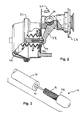
- FIG. 1 depicts a traditional brake system known in the art.
- FIG. 2 depicts a brake system in accordance with the invention.
- FIG. 3 depicts a push rod and ball end in accordance with the invention.
- FIG. 4a depicts the push rod positioned relative to the ball end.
- FIG. 4b depicts a force transfer member placed between the push rod and ball end in accordance with the invention.
- FIG. 5a depicts another embodiment of the ball end.
- FIG. 5b depicts another embodiment of the push rod.
- FIG. 5c depicts a perspective view of the ball end of FIG. 5a.
- FIG. 6 depicts a method for positioning the ball end relative to the push rod.
- FIG. 2 depicts a brake system 20, including a brake actuator 22, caliper 26 for grasping a disc brake (shown in FIG. 1) during braking, push rod 40, ball end 44, and arm 28 for receiving ball end 44 and transferring the force from ball end 44 to caliper 26.
- Braking is applied by a vehicle operator pressing on a brake pedal, which causes actuator 22 to push upon push rod 40, which in turn extends away from a mounting face surface 32 and pushes upon ball end 44, which in turn pushes upon arm 28.
- arm 28 rotates about pivot 34 and causes caliper 26 to grasp the disc brake, which brakes the axle and wheels.
- the overall length, represented by dimension L is shown in FIG. 4b.
- FIG. 3 more particularly depicts push rod 40 and ball end 44.
- ball end 44 is inserted into an opening 42 of push rod 40.
- Ball end 44 may be inserted to any depth into opening 42 along an inner diameter surface 46 of ball end 44.
- a shoulder 48 of ball end 44 will be a stopping point, and represents the maximum depth, for the insertion of inner diameter surface 46 into opening 42.
- FIGS. 4a and 4b depict a cross sectional view along a length of ball end 44 and push rod 40.
- ball end 44 is positioned relative to push rod 40 in accordance with the invention.
- FIG. 4a shows ball end 44 inserted to a desired depth within push rod 40.
- ball end 44 may be inserted into opening 42 to any position along inner diameter surface 46 up to a point where shoulder 48 contacts push rod 40.
- a depth of opening 42 is greater than a length of inner diameter surface 46, represented by D', so that ball end 44 does not bottom out, thereby limiting adjustment of ball end 44 relative to push rod 40.
- shims are generally placed between shoulder 48 and push rod 40 to fix a position of ball end 44 relative to push rod 40.
- the invention overcomes these disadvantages by using a force transfer member 50 instead of shims, as shown in FIG. 4b.
- a benefit of positioning ball end 44 relative to push rod 40 and all other components that affect overall length L prior to placing force transfer member 50 in cavity 54 is that this sequence reduces tolerance stack up. This is because overall length L is not dependent upon the amount of force transfer member 50 placed in cavity 54. Therefore, the tolerances, and tolerance stack up, associated with the components may be negated, corrected, or compensated for by positioning ball end 44 relative to push rod 40 and then fixing this position with force transfer member 50. Conversely, the amount of force transfer member 50 is dependent upon overall length L.
- This inventive sequence is very different from the traditional sequence of positioning shims to determine overall length L and final position of ball end 44 relative to push rod 40, where overall length L is dependent upon the amount of shims used.
- overall length L is subject to the tolerances, and tolerance stack up, associated with the components of the brake system.
- force transfer member 50 may be varied so that air bubbles are not trapped in cavity 54. Moreover, force transfer member 50 is continuously injected into hole 52 until it begins to back out of hole 52, thereby providing a visual indication that cavity 54 is filled since hole 52 has been filled.
- force transfer member 50 may be placed in cavity 54 prior to positioning ball end 44 relative to push rod 40.
- This embodiment achieves the benefit of reducing tolerance stack up provided force transfer member 50 is flowable so that, upon positioning ball end 44 into opening 42, excess force transfer member 50 and/or any trapped air may enter opening 42 and exit cavity 54.
- inner diameter surface 46 of ball end 44 includes a recess 58 for permitting air trapped between ball end 44 and push rod 40 to escape.
- Recess 58 may be a groove, knurl, channel, notch, relief, or any other recess in inner diameter surface 46. How recess 58 is formed is not germane to the invention. Moreover, multiple recesses 58 may be used to expedite the exit of trapped air.
- push rod 40 includes a protrusion 62 extending into ball end 44.
- outer diameter surface 64 of protrusion 62 includes recess 58 for permitting trapped air to escape. Recess 58 in outer diameter surface 64 may be used instead of or in addition to recess 58 in inner diameter surface 46.
- Force transfer member 50 may be of a variety of materials and be in a liquid or solid state.
- member 50 is molten zinc or a zinc alloy.
- member 50 is any flowable compound having an ability to be injected into hole 52 and cavity 54 and, subsequently, to harden and position ball end 44 relative to push rod 40. It is preferred for member 50 to be of an incompressible compound in both the solid and liquid states. In other embodiments, member 50 may be compressible in the liquid state but should, when hardened or solidified, be an incompressible solid material.
- member 50 solidifies or hardens after a passage of time without user intervention.
- an additive is combined with member 50 or member 50 is heated to facilitate solidification.
- Member 50 may be a solid, such as a powder, and is hardened after a solution is added to the powder.
- the additive may be injected into hole 52 prior to, during, or after member 50 is injected.
- the additive lines or coats opening 42 or cavity 54 so that, upon or subsequent to member 50 being injected through hole 52, member 50 begins to solidify.
- member 50 solidifies after a passage of time, no matter how small or large.
- the invention envisions member 50 solidifying upon coming in contact, or instantaneously, with the additive. In these embodiments, a fraction of a second may have passed between contact and solidification and it is understood that these embodiments are part of the invention.
- Force transfer member 50 may be injected using any known or novel injection machines.
- the machine for injecting force transfer 50 is not germane to the invention.
- FIG. 6 depicts a method 70 for positioning ball end 44 relative to push rod 40.
- Method 70 includes the steps of providing 72 a push rod, providing 74 a ball end, and positioning 76 ball end 44 relative to push rod 40.
- ball end 44 is positioned 76 relative to push rod 40 by inserting inner diameter surface 46 into opening 42 to a desired depth.
- method 70 includes placing 78 force transfer member 50 between push rod 40 and ball end 44.
- a benefit of positioning 76 ball end 44 relative to push rod 40 and all other components that affect overall length L prior to placing 78 force transfer member 50 in cavity 54 is that, in this sequence, method 70 reduces tolerance stack up. This benefit is more particularly described under FIGS. 4a and 4b.
- method 70 also includes the step of solidifying 80 force transfer member 50.
- method may include the step of adding 96 an additive to force transfer member 50 in order to facilitate solidification or hardening.
- Method may add 96 the additive as a requirement or as an aid for solidification.
- Method may add 96 the additive before, during, or after placing 78 the force transfer member in between push rod 40 and ball end 44.
- method 70 may include fixing 82, or locking, the position of ball end 44 relative to push rod 40. Fixing 82 the position may be either temporary or permanent, depending upon whether or not later adjustments or interchangeability of components of brake system 20 are envisioned.
- Method 70 may also include the step of providing 88 hole 52 in ball end 44, where hole 52 extends the entire length of ball end 44. Hole 52 permits placing 78 force transfer member 50 between push rod 40 and ball end 44 by injecting 90 member 50 into hole 52, which will then travel to and fill cavity 54.
- Method 70 may inject 90 member 50 into hole 52 until a desired pressure is achieved in member 50, thereby helping to ensure that cavity 54 is sufficiently filled and able to transfer forces between push rod 40 and ball end 44. To reduce air bubbles in cavity 54, which may negatively affect the ability of push rod 40 to transfer forces to ball end 44, method 70 may adjust 92 the pressure, temperature, and/or flow rate of force transfer member 50. Additionally, force transfer member 50 may be injected 90 into hole 52 until it begins to back out of hole 52, thereby providing a visual indication that cavity 54 is filled since hole 52 has been filled.
- method 70 may place 78 force transfer member 50 in cavity 54 prior to positioning 76 ball end 44 relative to push rod 40. This aspect achieves the benefit of reducing tolerance stack up provided force transfer member 50 is flowable so that, upon positioning 76 ball end 44 into opening 42, excess force transfer member 50 and/or any trapped air may enter opening 42 and exit cavity 54.
- method 70 may optionally include the step of providing 84 a groove in a surface, such as outer diameter surface 64 of protrusion 62 shown in FIG. 5b, of the push rod to release air trapped between the push rod and ball end.
- method 70 may optionally include the step of providing 86 a recess in a surface, such as inner diameter surface 46 of ball end 44 shown in FIG. 5a, of the ball end to release air trapped between the push rod and ball end.
Landscapes
- Engineering & Computer Science (AREA)
- Mechanical Engineering (AREA)
- General Engineering & Computer Science (AREA)
- Transportation (AREA)
- Braking Arrangements (AREA)
- Standing Axle, Rod, Or Tube Structures Coupled By Welding, Adhesion, Or Deposition (AREA)
- Actuator (AREA)
Applications Claiming Priority (2)
| Application Number | Priority Date | Filing Date | Title |
|---|---|---|---|
| US288122 | 2002-11-05 | ||
| US10/288,122 US6755233B2 (en) | 2002-11-05 | 2002-11-05 | Method and apparatus for positioning an end of a push rod of a brake actuator |
Publications (3)
| Publication Number | Publication Date |
|---|---|
| EP1418362A2 true EP1418362A2 (de) | 2004-05-12 |
| EP1418362A3 EP1418362A3 (de) | 2005-02-02 |
| EP1418362B1 EP1418362B1 (de) | 2006-07-26 |
Family
ID=32107623
Family Applications (1)
| Application Number | Title | Priority Date | Filing Date |
|---|---|---|---|
| EP03025214A Expired - Lifetime EP1418362B1 (de) | 2002-11-05 | 2003-11-05 | Verfahren und Vorrichtung zum Positionieren eines Stösselstangkopfes eines Bremsaktuators |
Country Status (6)
| Country | Link |
|---|---|
| US (2) | US6755233B2 (de) |
| EP (1) | EP1418362B1 (de) |
| JP (1) | JP4031750B2 (de) |
| KR (1) | KR100535900B1 (de) |
| DE (1) | DE60307016T2 (de) |
| HU (1) | HU226604B1 (de) |
Cited By (2)
| Publication number | Priority date | Publication date | Assignee | Title |
|---|---|---|---|---|
| EP2582998A4 (de) * | 2010-06-18 | 2017-04-19 | MGM Brakes | Elektronischer hubsensor für eine luftscheibenbremse |
| WO2018050810A1 (de) * | 2016-09-19 | 2018-03-22 | Knorr-Bremse Systeme für Nutzfahrzeuge GmbH | Pneumatische scheibenbremse |
Families Citing this family (10)
| Publication number | Priority date | Publication date | Assignee | Title |
|---|---|---|---|---|
| GB0312459D0 (en) * | 2003-05-30 | 2003-07-09 | Meritor Heavy Vehicle Braking | Air brake assembly |
| US7493993B2 (en) * | 2005-08-26 | 2009-02-24 | Haldex Brake Products Ab | Brake system having a reduced length and an axially mounted actuator |
| GB0608740D0 (en) * | 2006-05-03 | 2006-06-14 | Meritor Heavy Vehicle Braking | Improvements In Vehicle Braking Systems |
| US8319623B2 (en) | 2009-01-23 | 2012-11-27 | Mgm Brakes | Brake monitoring system and method |
| US20100299906A1 (en) * | 2009-05-28 | 2010-12-02 | Indian Head Industries, Inc. | Apparatus and method of forming the brake actuator |
| US9855940B2 (en) | 2010-06-18 | 2018-01-02 | Indian Head Industries, Inc. | Electronic stroke sensor for air disc brake |
| US9440633B2 (en) * | 2010-06-18 | 2016-09-13 | Indian Head Industries, Inc. | Electronic stroke sensor for air disc brake with inspection port |
| BR112018068162B1 (pt) * | 2016-03-09 | 2022-11-29 | Hendrickson Usa, L.L.C. | Sistema de freio a disco de ar para um veículo pesado e montagem de atuador de freio a disco de ar para um veículo pesado |
| CN109311465B (zh) * | 2016-05-20 | 2021-12-07 | 哈尔德克斯制动器产品公司 | 带隔膜保持器的弹簧制动致动器 |
| US10780874B2 (en) * | 2017-08-14 | 2020-09-22 | Hendrickson Usa, L.L.C. | Suspension assembly with disc brake actuator protection |
Citations (1)
| Publication number | Priority date | Publication date | Assignee | Title |
|---|---|---|---|---|
| US5579873A (en) | 1995-01-25 | 1996-12-03 | New York Air Brake Corporation | Brake actuator vibration isolation system |
Family Cites Families (19)
| Publication number | Priority date | Publication date | Assignee | Title |
|---|---|---|---|---|
| US4861256A (en) | 1986-06-23 | 1989-08-29 | The Anchor Group | Injection molding tool |
| US4960036A (en) | 1987-11-06 | 1990-10-02 | Indian Head Industries, Inc. | Tamper-resistant brake actuator |
| JPH084911B2 (ja) | 1989-01-30 | 1996-01-24 | 宇部興産株式会社 | 成形機用型締装置 |
| FR2693570B1 (fr) | 1992-07-08 | 1994-09-02 | Bendix Europ Services Tech | Dispositif de liaison à rappel élastique. |
| FR2704034B1 (fr) | 1993-04-15 | 1995-05-19 | Alliedsignal Europ Services | Frein à disque utilisant un patin tire à appui glissant. |
| DE4314720A1 (de) * | 1993-05-04 | 1994-11-10 | Knorr Bremse Ag | Druckluftbetätigte Scheibenbremse |
| DE4424721B4 (de) * | 1994-07-13 | 2004-02-12 | Knorr-Bremse Systeme für Nutzfahrzeuge GmbH | Bremszylinder für Scheibenbremsen, insbesondere von Nutzfahrzeugen |
| US5793561A (en) | 1994-10-14 | 1998-08-11 | Canon Kabushiki Kaisha | Rotary drum assembly having dynamic-pressure generating mechanism between rotary shaft and bearing |
| DE19515019A1 (de) * | 1995-04-24 | 1996-10-31 | Perrot Bremsen Gmbh | Scheibenbremse |
| SE508707C2 (sv) | 1995-10-02 | 1998-10-26 | Volvo Ab | Anordning vid skivbromsar för motorfordon |
| US5799564A (en) * | 1996-03-28 | 1998-09-01 | Nai Anchorlok, Inc. | Spring brake actuator having two-ply pressure plate assembly |
| JP4145960B2 (ja) * | 1996-12-18 | 2008-09-03 | クノル−ブレムゼ ジステーメ フューア ヌッツファールツォイゲ ゲゼルシャフト ミット ベシュレンクテル ハフツング | 車両用圧縮空気作動型ディスクブレーキ |
| ES2201565T3 (es) | 1997-12-16 | 2004-03-16 | Bpw Bergische Achsen Kommanditgesellschaft | Dispositivo de freno. |
| US6050372A (en) | 1998-03-18 | 2000-04-18 | Haldex Brake Corporation | Tamper-resistant brake actuator and method of making the same |
| JP2000348931A (ja) | 1999-06-08 | 2000-12-15 | Smc Corp | 電磁アクチュエータ |
| US6267043B1 (en) | 1999-10-29 | 2001-07-31 | Indian Head Industries, Inc. | Brake actuator assembly |
| US6250438B1 (en) * | 2000-01-28 | 2001-06-26 | Yih Cherng Co., Ltd. | Disc brake for a bicycle |
| US6349629B1 (en) | 2000-08-25 | 2002-02-26 | Indian Head Industries, Inc. | Brake actuator |
| US6371500B1 (en) | 2000-08-28 | 2002-04-16 | Spicer Technology, Inc. | Cam mechanism for an adjustable wheel mounting assembly |
-
2002
- 2002-11-05 US US10/288,122 patent/US6755233B2/en not_active Expired - Lifetime
-
2003
- 2003-11-05 HU HU0303654A patent/HU226604B1/hu not_active IP Right Cessation
- 2003-11-05 JP JP2003376005A patent/JP4031750B2/ja not_active Expired - Fee Related
- 2003-11-05 EP EP03025214A patent/EP1418362B1/de not_active Expired - Lifetime
- 2003-11-05 KR KR10-2003-0078024A patent/KR100535900B1/ko not_active Expired - Fee Related
- 2003-11-05 DE DE60307016T patent/DE60307016T2/de not_active Expired - Lifetime
-
2004
- 2004-05-13 US US10/844,775 patent/US7028814B2/en not_active Expired - Lifetime
Patent Citations (1)
| Publication number | Priority date | Publication date | Assignee | Title |
|---|---|---|---|---|
| US5579873A (en) | 1995-01-25 | 1996-12-03 | New York Air Brake Corporation | Brake actuator vibration isolation system |
Cited By (2)
| Publication number | Priority date | Publication date | Assignee | Title |
|---|---|---|---|---|
| EP2582998A4 (de) * | 2010-06-18 | 2017-04-19 | MGM Brakes | Elektronischer hubsensor für eine luftscheibenbremse |
| WO2018050810A1 (de) * | 2016-09-19 | 2018-03-22 | Knorr-Bremse Systeme für Nutzfahrzeuge GmbH | Pneumatische scheibenbremse |
Also Published As
| Publication number | Publication date |
|---|---|
| JP4031750B2 (ja) | 2008-01-09 |
| EP1418362A3 (de) | 2005-02-02 |
| HU226604B1 (hu) | 2009-04-28 |
| JP2004286208A (ja) | 2004-10-14 |
| US6755233B2 (en) | 2004-06-29 |
| KR20040040386A (ko) | 2004-05-12 |
| HUP0303654A2 (en) | 2006-04-28 |
| EP1418362B1 (de) | 2006-07-26 |
| US20040206588A1 (en) | 2004-10-21 |
| KR100535900B1 (ko) | 2005-12-09 |
| DE60307016D1 (de) | 2006-09-07 |
| US7028814B2 (en) | 2006-04-18 |
| DE60307016T2 (de) | 2007-02-15 |
| HU0303654D0 (en) | 2004-01-28 |
| US20040084255A1 (en) | 2004-05-06 |
Similar Documents
| Publication | Publication Date | Title |
|---|---|---|
| EP1418362B1 (de) | Verfahren und Vorrichtung zum Positionieren eines Stösselstangkopfes eines Bremsaktuators | |
| EP1485282B1 (de) | Elektrisch betätigbare fahrzeugbremse und verfahren zur steuerung einer elektrisch betätigbaren fahrzeugbremse | |
| KR20140036297A (ko) | 차량 내 주차 브레이크의 조절 방법, 폐회로 제어 및/또는 개회로 제어 유닛, 및 상기 유형의 폐회로 제어 및/또는 개회로 제어 유닛을 구비한 주차 브레이크 | |
| GB1509398A (en) | Automatic slack adjusters for vehicle brakes | |
| JP3237646B2 (ja) | ブレーキキャリパ鋳造用金型 | |
| EP1049887B1 (de) | Betätigungskolben für eine hydraulisch und mechanisch betätigbare teilbelag-scheibenbremse | |
| EP1676046B1 (de) | Feststellbremsen | |
| JP2010266037A (ja) | シール溝形成方法およびその方法を使用して形成したシール溝を有するディスクブレーキ | |
| JP2003301873A (ja) | ブレーキドラムの製造方法 | |
| MX2007001985A (es) | Freno de discos equipado con yugo de tamano reducido. | |
| JP4262416B2 (ja) | 車両用ディスクブレーキのキャリパボディ | |
| JP3280909B2 (ja) | 金属原料の射出成形用金型装置 | |
| JP2026022144A (ja) | 樹脂製部品および樹脂製部品の製造方法 | |
| EP0578352B1 (de) | Verfahren zur Herstellung eines Verschleisssensors für das Material des Bremsbackenbelages | |
| DE102005060024B4 (de) | Verfahren und Bremssystem zum Einstellen einer Nullposition einer Reibungsfläche | |
| JP5615867B2 (ja) | 機械式ディスクブレーキ用キャリパボディの製造方法 | |
| US20250243914A1 (en) | Composite brake calipers | |
| JP3740625B2 (ja) | インサート成形における圧入・保圧・離型方法 | |
| JP3671078B2 (ja) | 金属鋳造法 | |
| JPS6174924A (ja) | ブレ−キ用摩擦パツドの製造方法 | |
| JPH06154367A (ja) | ゴルフクラブのソールプレート | |
| JP2004154806A (ja) | 金型鋳造装置 | |
| JPS632671Y2 (de) | ||
| DE102023202256A1 (de) | Elektrische Brems-Messvorrichtung für eine Kraftfahrzeugradbremse | |
| JP2583951Y2 (ja) | 車両のブレーキギャップ調整用工具 |
Legal Events
| Date | Code | Title | Description |
|---|---|---|---|
| PUAI | Public reference made under article 153(3) epc to a published international application that has entered the european phase |
Free format text: ORIGINAL CODE: 0009012 |
|
| AK | Designated contracting states |
Kind code of ref document: A2 Designated state(s): AT BE BG CH CY CZ DE DK EE ES FI FR GB GR HU IE IT LI LU MC NL PT RO SE SI SK TR |
|
| AX | Request for extension of the european patent |
Extension state: AL LT LV MK |
|
| PUAL | Search report despatched |
Free format text: ORIGINAL CODE: 0009013 |
|
| AK | Designated contracting states |
Kind code of ref document: A3 Designated state(s): AT BE BG CH CY CZ DE DK EE ES FI FR GB GR HU IE IT LI LU MC NL PT RO SE SI SK TR |
|
| AX | Request for extension of the european patent |
Extension state: AL LT LV MK |
|
| 17P | Request for examination filed |
Effective date: 20050727 |
|
| AKX | Designation fees paid |
Designated state(s): DE FR GB IT SE |
|
| GRAP | Despatch of communication of intention to grant a patent |
Free format text: ORIGINAL CODE: EPIDOSNIGR1 |
|
| GRAS | Grant fee paid |
Free format text: ORIGINAL CODE: EPIDOSNIGR3 |
|
| GRAA | (expected) grant |
Free format text: ORIGINAL CODE: 0009210 |
|
| AK | Designated contracting states |
Kind code of ref document: B1 Designated state(s): DE FR GB IT SE |
|
| PG25 | Lapsed in a contracting state [announced via postgrant information from national office to epo] |
Ref country code: IT Free format text: LAPSE BECAUSE OF FAILURE TO SUBMIT A TRANSLATION OF THE DESCRIPTION OR TO PAY THE FEE WITHIN THE PRESCRIBED TIME-LIMIT;WARNING: LAPSES OF ITALIAN PATENTS WITH EFFECTIVE DATE BEFORE 2007 MAY HAVE OCCURRED AT ANY TIME BEFORE 2007. THE CORRECT EFFECTIVE DATE MAY BE DIFFERENT FROM THE ONE RECORDED. Effective date: 20060726 |
|
| REG | Reference to a national code |
Ref country code: GB Ref legal event code: FG4D |
|
| REF | Corresponds to: |
Ref document number: 60307016 Country of ref document: DE Date of ref document: 20060907 Kind code of ref document: P |
|
| REG | Reference to a national code |
Ref country code: SE Ref legal event code: TRGR |
|
| ET | Fr: translation filed | ||
| PLBE | No opposition filed within time limit |
Free format text: ORIGINAL CODE: 0009261 |
|
| STAA | Information on the status of an ep patent application or granted ep patent |
Free format text: STATUS: NO OPPOSITION FILED WITHIN TIME LIMIT |
|
| 26N | No opposition filed |
Effective date: 20070427 |
|
| PGFP | Annual fee paid to national office [announced via postgrant information from national office to epo] |
Ref country code: IT Payment date: 20081127 Year of fee payment: 6 Ref country code: SE Payment date: 20081112 Year of fee payment: 6 |
|
| EUG | Se: european patent has lapsed | ||
| PG25 | Lapsed in a contracting state [announced via postgrant information from national office to epo] |
Ref country code: IT Free format text: LAPSE BECAUSE OF NON-PAYMENT OF DUE FEES Effective date: 20091105 |
|
| PG25 | Lapsed in a contracting state [announced via postgrant information from national office to epo] |
Ref country code: SE Free format text: LAPSE BECAUSE OF NON-PAYMENT OF DUE FEES Effective date: 20091106 |
|
| REG | Reference to a national code |
Ref country code: FR Ref legal event code: PLFP Year of fee payment: 13 |
|
| REG | Reference to a national code |
Ref country code: FR Ref legal event code: PLFP Year of fee payment: 14 |
|
| REG | Reference to a national code |
Ref country code: FR Ref legal event code: PLFP Year of fee payment: 15 |
|
| PGFP | Annual fee paid to national office [announced via postgrant information from national office to epo] |
Ref country code: DE Payment date: 20191029 Year of fee payment: 17 |
|
| PGFP | Annual fee paid to national office [announced via postgrant information from national office to epo] |
Ref country code: FR Payment date: 20191028 Year of fee payment: 17 |
|
| PGFP | Annual fee paid to national office [announced via postgrant information from national office to epo] |
Ref country code: GB Payment date: 20191024 Year of fee payment: 17 |
|
| REG | Reference to a national code |
Ref country code: DE Ref legal event code: R119 Ref document number: 60307016 Country of ref document: DE |
|
| GBPC | Gb: european patent ceased through non-payment of renewal fee |
Effective date: 20201105 |
|
| PG25 | Lapsed in a contracting state [announced via postgrant information from national office to epo] |
Ref country code: FR Free format text: LAPSE BECAUSE OF NON-PAYMENT OF DUE FEES Effective date: 20201130 |
|
| PG25 | Lapsed in a contracting state [announced via postgrant information from national office to epo] |
Ref country code: GB Free format text: LAPSE BECAUSE OF NON-PAYMENT OF DUE FEES Effective date: 20201105 Ref country code: DE Free format text: LAPSE BECAUSE OF NON-PAYMENT OF DUE FEES Effective date: 20210601 |