EP1417062B1 - Centrifugal countergravity casting - Google Patents
Centrifugal countergravity casting Download PDFInfo
- Publication number
- EP1417062B1 EP1417062B1 EP02759373.0A EP02759373A EP1417062B1 EP 1417062 B1 EP1417062 B1 EP 1417062B1 EP 02759373 A EP02759373 A EP 02759373A EP 1417062 B1 EP1417062 B1 EP 1417062B1
- Authority
- EP
- European Patent Office
- Prior art keywords
- mold
- molten metal
- riser passage
- container
- passage
- Prior art date
- Legal status (The legal status is an assumption and is not a legal conclusion. Google has not performed a legal analysis and makes no representation as to the accuracy of the status listed.)
- Expired - Lifetime
Links
- 238000005266 casting Methods 0.000 title claims description 59
- 229910052751 metal Inorganic materials 0.000 claims description 207
- 239000002184 metal Substances 0.000 claims description 207
- 238000000034 method Methods 0.000 claims description 44
- 238000011049 filling Methods 0.000 claims description 23
- 239000000919 ceramic Substances 0.000 claims description 21
- 230000004044 response Effects 0.000 claims description 9
- 239000011800 void material Substances 0.000 claims description 8
- 230000006378 damage Effects 0.000 claims 2
- 229910045601 alloy Inorganic materials 0.000 description 18
- 239000000956 alloy Substances 0.000 description 18
- 230000008569 process Effects 0.000 description 10
- 238000007711 solidification Methods 0.000 description 10
- 230000008023 solidification Effects 0.000 description 10
- 230000002829 reductive effect Effects 0.000 description 9
- 230000036961 partial effect Effects 0.000 description 8
- VYPSYNLAJGMNEJ-UHFFFAOYSA-N Silicium dioxide Chemical compound O=[Si]=O VYPSYNLAJGMNEJ-UHFFFAOYSA-N 0.000 description 7
- 239000007788 liquid Substances 0.000 description 7
- 239000002002 slurry Substances 0.000 description 7
- 229910000831 Steel Inorganic materials 0.000 description 6
- 150000002739 metals Chemical class 0.000 description 6
- 239000010959 steel Substances 0.000 description 6
- 239000011248 coating agent Substances 0.000 description 5
- 238000000576 coating method Methods 0.000 description 5
- 230000001965 increasing effect Effects 0.000 description 5
- 230000006698 induction Effects 0.000 description 5
- 239000000463 material Substances 0.000 description 5
- 230000008878 coupling Effects 0.000 description 4
- 238000010168 coupling process Methods 0.000 description 4
- 238000005859 coupling reaction Methods 0.000 description 4
- 230000009471 action Effects 0.000 description 3
- 229910052782 aluminium Inorganic materials 0.000 description 3
- XAGFODPZIPBFFR-UHFFFAOYSA-N aluminium Chemical compound [Al] XAGFODPZIPBFFR-UHFFFAOYSA-N 0.000 description 3
- 238000005058 metal casting Methods 0.000 description 3
- 230000004048 modification Effects 0.000 description 3
- 238000012986 modification Methods 0.000 description 3
- 230000035699 permeability Effects 0.000 description 3
- 230000009467 reduction Effects 0.000 description 3
- 239000004576 sand Substances 0.000 description 3
- 210000003625 skull Anatomy 0.000 description 3
- 229910000851 Alloy steel Inorganic materials 0.000 description 2
- XEEYBQQBJWHFJM-UHFFFAOYSA-N Iron Chemical compound [Fe] XEEYBQQBJWHFJM-UHFFFAOYSA-N 0.000 description 2
- PPBRXRYQALVLMV-UHFFFAOYSA-N Styrene Chemical compound C=CC1=CC=CC=C1 PPBRXRYQALVLMV-UHFFFAOYSA-N 0.000 description 2
- 239000000853 adhesive Substances 0.000 description 2
- 230000001070 adhesive effect Effects 0.000 description 2
- 239000003570 air Substances 0.000 description 2
- PNEYBMLMFCGWSK-UHFFFAOYSA-N aluminium oxide Inorganic materials [O-2].[O-2].[O-2].[Al+3].[Al+3] PNEYBMLMFCGWSK-UHFFFAOYSA-N 0.000 description 2
- 230000008901 benefit Effects 0.000 description 2
- 230000015572 biosynthetic process Effects 0.000 description 2
- 238000002485 combustion reaction Methods 0.000 description 2
- 230000007547 defect Effects 0.000 description 2
- 230000003111 delayed effect Effects 0.000 description 2
- KZHJGOXRZJKJNY-UHFFFAOYSA-N dioxosilane;oxo(oxoalumanyloxy)alumane Chemical compound O=[Si]=O.O=[Si]=O.O=[Al]O[Al]=O.O=[Al]O[Al]=O.O=[Al]O[Al]=O KZHJGOXRZJKJNY-UHFFFAOYSA-N 0.000 description 2
- 239000006260 foam Substances 0.000 description 2
- 239000005350 fused silica glass Substances 0.000 description 2
- 230000005484 gravity Effects 0.000 description 2
- 238000007654 immersion Methods 0.000 description 2
- 238000011065 in-situ storage Methods 0.000 description 2
- 238000005495 investment casting Methods 0.000 description 2
- 238000011068 loading method Methods 0.000 description 2
- 238000004519 manufacturing process Methods 0.000 description 2
- 239000000155 melt Substances 0.000 description 2
- 230000008018 melting Effects 0.000 description 2
- 238000002844 melting Methods 0.000 description 2
- 229910052863 mullite Inorganic materials 0.000 description 2
- 239000011819 refractory material Substances 0.000 description 2
- 238000007789 sealing Methods 0.000 description 2
- 229920001169 thermoplastic Polymers 0.000 description 2
- 239000004416 thermosoftening plastic Substances 0.000 description 2
- 229910052845 zircon Inorganic materials 0.000 description 2
- GFQYVLUOOAAOGM-UHFFFAOYSA-N zirconium(iv) silicate Chemical compound [Zr+4].[O-][Si]([O-])([O-])[O-] GFQYVLUOOAAOGM-UHFFFAOYSA-N 0.000 description 2
- 241000272517 Anseriformes Species 0.000 description 1
- OKTJSMMVPCPJKN-UHFFFAOYSA-N Carbon Chemical compound [C] OKTJSMMVPCPJKN-UHFFFAOYSA-N 0.000 description 1
- 229910001018 Cast iron Inorganic materials 0.000 description 1
- CWYNVVGOOAEACU-UHFFFAOYSA-N Fe2+ Chemical compound [Fe+2] CWYNVVGOOAEACU-UHFFFAOYSA-N 0.000 description 1
- 229910000990 Ni alloy Inorganic materials 0.000 description 1
- BOTDANWDWHJENH-UHFFFAOYSA-N Tetraethyl orthosilicate Chemical compound CCO[Si](OCC)(OCC)OCC BOTDANWDWHJENH-UHFFFAOYSA-N 0.000 description 1
- 230000001154 acute effect Effects 0.000 description 1
- 239000012080 ambient air Substances 0.000 description 1
- 238000003491 array Methods 0.000 description 1
- 239000011324 bead Substances 0.000 description 1
- 230000009286 beneficial effect Effects 0.000 description 1
- 239000011230 binding agent Substances 0.000 description 1
- 238000009750 centrifugal casting Methods 0.000 description 1
- 229910010293 ceramic material Inorganic materials 0.000 description 1
- 230000008859 change Effects 0.000 description 1
- 239000008119 colloidal silica Substances 0.000 description 1
- 230000000295 complement effect Effects 0.000 description 1
- 239000000470 constituent Substances 0.000 description 1
- 230000008602 contraction Effects 0.000 description 1
- 238000005520 cutting process Methods 0.000 description 1
- 230000002950 deficient Effects 0.000 description 1
- 230000001627 detrimental effect Effects 0.000 description 1
- 238000007598 dipping method Methods 0.000 description 1
- 238000001035 drying Methods 0.000 description 1
- 230000000694 effects Effects 0.000 description 1
- 230000002708 enhancing effect Effects 0.000 description 1
- 229920006248 expandable polystyrene Polymers 0.000 description 1
- 239000004794 expanded polystyrene Substances 0.000 description 1
- 230000005294 ferromagnetic effect Effects 0.000 description 1
- 239000000835 fiber Substances 0.000 description 1
- 239000012530 fluid Substances 0.000 description 1
- 230000004927 fusion Effects 0.000 description 1
- 239000003292 glue Substances 0.000 description 1
- PCHJSUWPFVWCPO-UHFFFAOYSA-N gold Chemical compound [Au] PCHJSUWPFVWCPO-UHFFFAOYSA-N 0.000 description 1
- 239000010931 gold Substances 0.000 description 1
- 229910052737 gold Inorganic materials 0.000 description 1
- 229910002804 graphite Inorganic materials 0.000 description 1
- 239000010439 graphite Substances 0.000 description 1
- 238000010438 heat treatment Methods 0.000 description 1
- 239000007943 implant Substances 0.000 description 1
- 229910052742 iron Inorganic materials 0.000 description 1
- 230000000670 limiting effect Effects 0.000 description 1
- 229910001338 liquidmetal Inorganic materials 0.000 description 1
- 230000014759 maintenance of location Effects 0.000 description 1
- 230000007246 mechanism Effects 0.000 description 1
- 239000010445 mica Substances 0.000 description 1
- 229910052618 mica group Inorganic materials 0.000 description 1
- 239000000203 mixture Substances 0.000 description 1
- 239000002245 particle Substances 0.000 description 1
- 238000005192 partition Methods 0.000 description 1
- 239000004033 plastic Substances 0.000 description 1
- 239000000843 powder Substances 0.000 description 1
- 238000005086 pumping Methods 0.000 description 1
- 239000010453 quartz Substances 0.000 description 1
- 230000000717 retained effect Effects 0.000 description 1
- 230000002441 reversible effect Effects 0.000 description 1
- 238000000926 separation method Methods 0.000 description 1
- 230000000087 stabilizing effect Effects 0.000 description 1
- 239000010935 stainless steel Substances 0.000 description 1
- 229910001220 stainless steel Inorganic materials 0.000 description 1
- 230000003068 static effect Effects 0.000 description 1
- 239000000725 suspension Substances 0.000 description 1
Images


Classifications
-
- B—PERFORMING OPERATIONS; TRANSPORTING
- B22—CASTING; POWDER METALLURGY
- B22D—CASTING OF METALS; CASTING OF OTHER SUBSTANCES BY THE SAME PROCESSES OR DEVICES
- B22D13/00—Centrifugal casting; Casting by using centrifugal force
-
- B—PERFORMING OPERATIONS; TRANSPORTING
- B22—CASTING; POWDER METALLURGY
- B22D—CASTING OF METALS; CASTING OF OTHER SUBSTANCES BY THE SAME PROCESSES OR DEVICES
- B22D13/00—Centrifugal casting; Casting by using centrifugal force
- B22D13/04—Centrifugal casting; Casting by using centrifugal force of shallow solid or hollow bodies, e.g. wheels or rings, in moulds rotating around their axis of symmetry
-
- B—PERFORMING OPERATIONS; TRANSPORTING
- B22—CASTING; POWDER METALLURGY
- B22D—CASTING OF METALS; CASTING OF OTHER SUBSTANCES BY THE SAME PROCESSES OR DEVICES
- B22D18/00—Pressure casting; Vacuum casting
- B22D18/06—Vacuum casting, i.e. making use of vacuum to fill the mould
Definitions
- the present invention relates to centrifugal countergravity casting of metals and alloys.
- US 4,763,717 discloses a method for melting and casting of metals and alloys which consists of utilizing a compact assembly for melting and centrifugal casting of metals, including a mold or chiller which is rotatable around a vertical axis.
- a countergravity casting process for making investment castings in gas permeable ceramic shell molds is described in US Patents 3 863 706 ; 3 900 064 ; 4 589 466 ; and 4 791 977 .
- the ceramic shell mold is formed by the well known "lost wax" process and includes an upstanding riser passage around which are located arrays of mold cavities in the shape of the cast articles to be made.
- the mold cavities are located along the length of the riser passage from proximate a bottom to a top thereof, and each mold cavity communicates to the riser passage via one or more relatively narrow feed gate passages depending upon the configuration of the mold cavity.
- the ceramic mold is disposed in a vacuum container, and a fill tube is communicated to the bottom of the riser passage and extends out of the container for immersion in an underlying pool of molten metal.
- a relative vacuum subambient pressure
- the molten metal in the gate passages and mold cavities typically is solidified before the vacuum in the container is released, although US Patent 3 863 706 discloses releasing the vacuum in the container after the molten metal in the gate passages and mold cavities has solidified to produce individual cast articles and to allow return of still molten metal in the riser passage to the underlying pool for reuse.
- the ceramic shell mold can be disposed in a particulate support media, such as dry foundry sand, in the vacuum container as described in US Patent 5 069 271 .
- the thickness of the shell mold wall can be reduced by use of the support media in the vacuum container.
- the container is evacuated using a vacuum head that also compresses the support media about the shell mold as a subambient pressure is established in the container.
- Countergravity casting methods result in a large variation in the time that it takes to fill identical mold cavities located at different elevations along the length of the upstanding riser sprue.
- the time needed to fill mold cavities of the same shell mold can vary by a factor of two or more.
- the lowermost mold cavities take the longest to fill with molten metal and the uppermost mold cavities take the shortest time. Delayed filling of the lowermost mold cavities can result in incomplete filling thereof with molten metal. Rapid filling of the uppermost mold cavities can result in entrapped gas defects in the solidified cast articles formed in those mold cavities.
- attempts to ameliorate one of the these problems further promotes the detrimental effects of the other.
- Countergravity casting methods also result in a large variation in the pressure in the mold cavities.
- the pressure in each mold cavity is equal to atmospheric pressure pushing on the surface of the molten metal pool when the container is evacuated minus the static pressure of the molten metal in the riser passage that acts counter to the atmospheric pressure on the pool surface.
- the pressure in the mold cavities depends on their elevation along the length of the riser passage; more particularly, the pressure depends on the difference in elevation between the surface of molten metal pool and the gate of the mold cavity.
- the taller the shell mold the greater is the pressure variation among mold cavities along the length of the sprue.
- the pressure reduction increases shrinkage and entrapped gas defects in mold cavities located higher up along the riser.
- the upper mold cavities may not yet be completely filled with molten metal.
- the riser passage is filled to the top end, the molten metal impacts the top end of the riser passage such that there thus is a resulting surge in pressure differential across the gate passages of the upper mold cavities that causes the upper mold cavities to fill too quickly.
- Much of any gas entrained in the molten metal in the riser passage is carried into the mold cavities where it can remain in the solidified cast articles formed in the mold cavities.
- the fill tube is kept immersed in the molten pool sufficiently long for the molten metal to solidify in the mold cavities and gate passages. Having to maintain immersion of the fill tube slows the casting cycle time and requires that the mold follow the dropping level of molten metal in the pool such that the mold become more and more exposed to the induction field that is used to heat the pool.
- the induction field can retard, or reverse, solidification in the mold and distort the container proximate the fill tube in a manner that permits airflow into the lower mold cavities. Gating design becomes a struggle between having gate passages with sufficient volume to feed the mold cavities, yet narrow enough to solidify molten metal in a timely manner therein.
- these constraints on gate design limit the size of cast articles that can be made by the process described in US Patent 3 863 706 to usually less than one pound.
- An object of the present invention is to provide a centrifugal countergravity casting method and apparatus that overcomes the above described problems and compromises associated with filling of mold cavities at different elevations along the length of the riser passage.
- Another object of the invention is to provide a casting method and apparatus for trapping molten metal or alloy in the mold cavities and gates through centrifugal action, while allowing for the voiding of the molten metal from the riser, resulting in castings unattached to the riser.
- the present invention provides in one embodiment method and apparatus for countergravity casting a plurality of articles wherein a ceramic mold is provided having an upstanding riser passage and a plurality of mold cavities disposed along a length of the riser passage at different elevations, each mold cavity communicating to the riser passage via a gate passage, wherein molten metal is caused to flow upwardly from a source into the riser passage for supply to the mold cavities via their gate passages, wherein the mold is rotated so that molten metal that resides in the gate passages is subjected to centrifugal force in a direction toward the mold cavities, and wherein molten metal in the riser passage is drained to empty the riser passage before molten metal in the mold cavities and the gate passages completely solidifies, leaving the gate passages at least partially filled with molten metal for supply to the mold cavities in response to shrinkage as molten metal therein solidifies while the container is rotated.
- the molten metal in the mold cavities is solidified while rotating the container to form a plurality of individual solidified cast articles in the mold cavities. Rotation of the mold can be terminated after molten metal solidifies in the mold cavities.
- Much higher yields of metal or alloy of 80% and above are achievable by practice of the invention.
- a much greater number and larger size of articles with increased density due to reduced shrinkage can be cast in practice of the invention.
- the steps of causing the molten metal to flow upwardly into the riser passage and of rotating the mold are conducted concurrently during filling of the mold cavities when casting molten metals that are prone to shrinkage problems. These steps optionally can be conducted sequentially with mold rotation being initiated after the molten metal is caused to flow upwardly to fill the mold cavities.
- the mold can be rotated about a longitudinal axis of the mold or an axis offset from and substantially parallel to a longitudinal axis of the mold.
- each mold cavity is elongated in the direction of the riser passage and is positioned (e.g. tilted) relative to the riser passage such that a theoretical melt surface provided by mold rotation passes only through the gate passages during draining of the riser passage but does not pass through the mold cavities so that molten metal is not voided from the mold cavities as the riser passage is drained.
- each mold cavity is elongated in the direction of the riser passage and is connected thereto by a plurality of gate passages at different elevations on the riser passage.
- Molten metal is initially solidified at regions in the mold cavity between the gate passages so to confine still molten metal in a plurality of more or less discrete compartments in the mold cavity between the solidified regions such that the gate passages partially filled with molten metal will supply still molten metal therein to a respective compartment in response to shrinkage as molten metal solidifies while the container is rotated.
- the invention can be practiced using gas permeable molds and gas impermeable molds.
- the invention is further beneficial in casting gas impermeable molds to reduce or eliminate entrapped gas in the mold cavities thereof.
- the ceramic mold is supported in a particulate medium, such as for example dry foundry sand, in an evacuable container.
- a particulate medium such as for example dry foundry sand
- the container is evacuated to subambient pressure to force molten metal upwardly into the mold riser passage and rotated by a rotary drive mechanism disposed on a support frame on which the container is mounted for rotation.
- the present invention envisions in still another embodiment of the invention replacing the ceramic mold with a fugitive pattern in the container.
- the fugitive pattern is supported in a particulate medium in the container and includes an upstanding riser passage-forming portion and a plurality of mold cavity-forming portions disposed along a length of the riser passage-forming portion at different elevations.
- Each mold cavity-forming portion communicates to the riser passage-forming portion via a gate passage-forming portion.
- the molten metal progressively destroys the pattern to form a riser passage, mold cavities and gate passages in the particulate medium.
- the invention achieves more uniform time of filling of the mold cavities at all elevations as well as more uniform pressure in the mold cavities and reduction of pressure surge proximate the upper mold cavities, reducing gas entrapment in the cast articles.
- the present invention provides a method and apparatus for centrifugal countergravity casting of a wide variety of components of different types and shapes using a wide variety of metals and alloys where the terminology "metal” as used hereabove and hereafter is intended to include metals and alloys.
- Typical components that can be made by centrifugal countergravity casting include for purposes of illustration, and not limitation, vehicle (e.g. automotive) internal combustion engine pistons, rocker arms, seat belt components, pre-combustion chambers; gas turbine engine nozzles and turbine blades; missile nose cones, fins, canards, fin actuators, gun components, gold clubs, hand tool components, medical implants, and myriad other components.
- Such metals and alloys include, but are not limited to, iron, steel, stainless steel, aluminum, nickel alloys and others.
- the invention is useful for centrifugal countergravity casting of small and large investment castings alike with identical casting apparatus except for the ceramic shell molds used, rapid casting cycle times, high loading of mold cavities along the riser passage, and high utilization of the metal being cast.
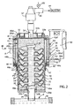
- a gas permeable ceramic shell mold 10 is formed pursuant to the well known lost wax process where a fugitive (e.g. wax) pattern assembly (not shown) of the mold 10 is dipped in ceramic slurry (e.g. a suspension of refractory powder such as zircon, alumina, fused silica and others in a liquid binder such as ethyl silicate or colloidal silica sol), excess slurry is drained from the pattern assembly, and the slurry coated pattern assembly is sanded or stuccoed with dry coarser refractory particles (e.g.
- ceramic slurry e.g. a suspension of refractory powder such as zircon, alumina, fused silica and others in a liquid binder such as ethyl silicate or colloidal silica sol
- US Patent 5 069 271 describes the lost wax process for making a thin-walled ceramic shell mold on a pattern assembly for use in practicing the invention.
- the resulting shell mold 10 has porous, gas permeable mold walls 10w.
- the ceramic shell mold 10 includes an upstanding riser passage 12 communicated by a respective lateral gate passage 14 to a respective mold cavity 16 having the shape of the component to be cast.
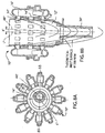
- a plurality of individual mold cavities 16 can be spaced apart about the periphery (e.g. circumference) of the riser passage 12 at different elevations (i.e. different axial locations) along the length of the riser passage 12 as illustrated in Figures 1-3 .
- eight gate passages 14 are provided to supply molten metal to eight mold cavities 16 spaced apart about the circumference of the riser passage at each elevation (axial location) along the length of the riser passage 12.
- a total of 112 mold cavities 16 are thereby provided in the mold 10.
- mold cavities typically, 6 to 12 mold cavities are located at each level when making smaller castings.
- Figure 3A where like features are designated by like reference numerals, 3 to 4 mold cavities 16 can be provided at a given mold elevation in 3 to 5 rows along the elevation of the mold 10.
- the gate passages 14 are normally much wider than those shown in Figures 1-3 .
- the wide gate passages 14 are needed to supply sufficient feed metal during the solidification process. Gate passages 14 that are 1 inch by 2 inches are not unusual; for example, see Figure 3A .
- annular mold cavity (not shown) can be disposed about the periphery of the riser passage 12 at different elevations along the length of the riser passage with each annular mold cavity communicated to the riser passage 12 by one or more gate passages.
- annular mold cavity having the shape of a gas turbine nozzle ring can be disposed at different axial locations along the length of the riser passage so that a plurality of nozzle rings can be cast in the mold 10.
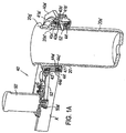
- the ceramic shell mold 10 is positioned in a rotatable metal (e.g. only steel) vacuum flask or container 20.
- the open lower end 10a of the mold 10 is placed on a sealing collar 23 that in turn is placed on a sealing collar 24a of an upstanding tubular fill tube 24 that extends outside the container via opening 20a in bottom wall 20w thereof.
- Thermoplastic glue or a ceramic fiber gasket can be placed between the lower end 10a and collar 24a, although the lower end 10a can rest directly on collar 24a with molten metal solidifying in any gap to provide an in-situ seal therebetween.
- the collar 24a includes annular seal gasket 24b on the underside thereof that faces the bottom wall 20w of the container.
- the fill tube typically comprises a ceramic material (e.g. mullite material when casting ferrous materials), although the fill tube can comprise any other material compatible with the molten metal being cast.
- a porous gas permeable refractory cap 26 is placed and optionally adhered by thermoplastic adhesive on the upper open end 12c of the riser passage 12 to close off the upper end.
- a gas-impervious cap or plug also can be used to close off the open end 12c.
- the mold 10 is surrounded and supported in rotatable vacuum container 20 by a refractory particulate support medium 22 (e.g. dry free-flowing foundry media such as lake bottom sand).
- the particulate medium 22 typically is introduced into the container 20 about the shell mold 10 through open upper container end 20se while the container is vibrated to aid in settling and compacting the particulates about the mold.
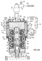
- a movable top vacuum bell or head 32 then is placed in open container end 20se.
- the vacuum head 32 includes an annular air-inflatable seal 32a that seals in airtight manner against the upstanding side wall 20s of the container.
- a perforated plate or screen 32b of the vacuum head 32 faces the particulate medium 22.
- the vacuum head 32 is connected to a vacuum conduit 34 having a conventional rotary vacuum union or coupling 37 that permits conduit 34 and the container 20 to be rotated relative to conduit 35 while evacuating the interior of the container 20.
- a rotary coupling 37 useful in practicing the invention is commercially available as a 2 inch rotary vacuum coupling from Deublin Company, Waukegan, Illinois.
- the interior of the container 20 is evacuated to subambient pressure by a vacuum pump PP connected to non-rotating conduit 35 that communicates to conduit 34 via coupling 37.
- the conduit 34 includes one or more openings 34a that communicate the vacuum pump PP to the interior of the vacuum head 32, which communicates to the interior of the container 20 via the perforated plate or screen 32b.
- the container 20 is rotatably disposed on a frame 40.
- the frame 40 comprises an upper annular frame collar or flange member 41 welded to the upper end of wall 20s of container 20.
- Flange member 41 supports the weight of the container and its contents and transmits the load to a cylindrical frame shell member 42 via a conventional upper anti-friction angular contact bearing 43 that is disposed on a recessed shoulder 42s1 of tubular shell member 42.
- the shell member 42 is adapted to be grabbed on the outside by robotic jaws A.
- Bearing 43 comprises an inner race 43a, outer race 43b and multiple balls 43c therebetween.
- a conventional lower anti-friction bearing 44 is disposed and held in position in an annular lower recessed shoulder 42s2 of tubular frame member 42 between frame member 42 and a lower annular frame collar member 45 affixed by fasteners 46 to the frame member 42.
- Bearing 44 comprises an inner race 44a, outer race 44b and multiple balls 44c therebetween, Figure 1C .
- the frame members 41, 42, 45 are connected to the container 20 to form an assembly or cartridge for use in a casting machine having a robotic manipulator with gripper jaws A.
- the container 20 is received in the tubular frame member 42 with the inner races 43a, 44a of anti-friction bearings 43, 44 rotatably supporting the container 20 so that the container 20 can be rotated about an axis (vertical axis L in Fig. 1 ) corresponding generally to the central longitudinal axis of the riser passage 12.
- the container 20 includes a thicker upper wall region 20s1 and lower wall region 20s2 received and engaging the inner race 43a and 44a of the anti-friction bearings 43, 44, respectively.
- Three conventional circumferentially spaced apart crescents 47 each with a slotted mounting hole are bolted by bolts 48 to the side of container 20s.
- the cresents each include a tapered surface 47f that engages a complementary tapered surface 20f of the container wall, Figure 1C .
- the crescents function to take out play between angular contact bearings 43, 44.
- the crescents 47 also support the weight of the container 20s when the cartridge is inverted upside-down.
- the container is rotated on frame 40 by a motor 50 having a drive sprocket 50a that drives a belt 52 extending about and frictionally drivingly engaging the outer surface 20o of the container wall 20s.
- the belt 52 extends through a slot 42o in shell member 42.
- the motor 50 can comprise a variable speed DC motor, although any type of electrical, fluid or other drive motor can be used in practicing the invention.
- a 1 HP (horsepower) variable speed DC motor available as model T56S2013 from Reliance Electric Company can be used to practice the invention.
- the motor 50 is fastened on frame member 42 by fasteners 54 and mounting plate 56.
- the belt 52 can comprise a 1 inch wide, 1/2 inch pitch, 114 teeth timing belt model 570H100 available from Gates Rubber Company that is driven by a Dodge 16H100TLA timing pulley available from Daimler Chrysler Corporation and that frictionally engages the container outer surface such that rotation of the belt by sprocket 50a rotates the container 20 and its contents.
- the frame 40 is gripped and moved by robotic gripper arms A of a casting machine (not shown).
- the gripping arms A engage the middle of tubular frame shell member 42.
- the invention is not limited to such gripper arms as other devices, such as robotic motion devices, or manual movement by a worker can be used to move the frame 40 and container 20 thereon.
- the arms A alternately may be part of a casting machine of the type disclosed in US Patent 4 874 029 .
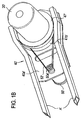
- FIG. 1A and 1B where like reference numerals are used to designate like features of Figures 1-3 , a vacuum container 20' and frame 40' are shown having a somewhat different configuration.
- the container 20' includes an outwardly tapering wall region 20s1' on upstanding wall 20s' and terminating in a radially extending upper shoulder 20g'.
- Anti-friction bearings 43', 44' are disposed between inner ring 41a' and an outer ring 41b'.
- Each bearing 43' and 44' includes inner race 43a', 44a' and outer race 43b', 44b' with balls 43c' 44c'.
- a lower annular retainer 47' is fastened on the ring 41a' to support the bearing 44'.
- Outer ring 41b' is fixedly mounted (e.g. welded) on an elongated support frame member 40a' which is affixed (e.g. welded) to arm A'.
- Inner ring 41a' is supported by the bearings 43', 44' and caused to rotate by timing belt 52'.
- An electric or other motor 50' is mounted on the elongated frame 40' and includes a drive sprocket 50a' that drives a belt 52' frictionally engaging inner ring 41a' so as to rotate the container 20', Figure 1A . For example, when inner ring 41a' is rotated, container 20' is caused to rotate by friction with the inner ring.
- the frame 40' is shown supported for movement by arms A' of a casting machine.
- the arms A' are fixed relative to one another and engage the underside of frame member 40a' , Figure 1B .
- the container 20' and frame 40' can be used in lieu of container 20 and frame 40 of Figures 1-3 in practicing of the invention as described above.
- the container 20' would receive a shell mold 10, particulate medium 22 about the mold, and vacuum head 32 in the manner described above but not shown in Figures 1A and 1B for convenience.
- the container 20 (or 20') is moved from a loading station (not shown) where the mold 10, particulate medium 22, and vacuum head 32 are assembled therein and then to a casting position, Figure 1 , where the container 20 (20') is positioned by arms A (A') of the casting machine above a source S of molten metal to be cast into the mold 10.
- the source S is illustrated as comprising a molten metallic pool P (e.g. molten metal or alloy) contained in a crucible C and heated by induction coils (not shown) about the crucible as shown for example in US Patent 3 863 706 , the teachings of which are incorporated herein by reference.
- a molten metallic pool P e.g. molten metal or alloy
- the container 20 is rotated by actuation of motor 50 before or after the fill tube 24 is immersed in the pool P.
- one illustrative motion sequence involves rotating the container 20 above pool P, then immersing the fill tube 24 in pool P, and then evacuating the container 20 to provide subambient pressure therein by actuation of vacuum pump PP.
- Another illustrative sequence involves immersing the fill tube 24 in pool P and then evacuating the container 20 to subambient pressure followed by rotation of the container.
- Other sequences can be employed.
- Subambient pressure in the container can be in the range of 13 inches Hg to 18 inches Hg for practicing the invention to force up to 150 pounds or more of molten metal or alloy to flow upwardly into the mold 10, although the invention is not so limited as other vacuum levels in the container 20, and/or increasing pressure over the molten metal surface of pool P to provide superambient pressure on pool P with or without subambient pressure in container 20, can be used depending upon the countergravity casting parameters employed, mold configuration employed, and molten metal or alloy being cast. Rotational speeds of the container will depend in part on the size (e.g. diameter) of the riser passage 12 and can be in the range of 150 to 300 rpm.
- a rotational speed of 300 rpm can be used with a riser passage 12 having a diameter of 3 inches.
- a rotational speed of 150-200 rpm can be used with a riser passage 12 having a diameter of 5 inches.
- the invention is not limited to any particular rotational speed which can be selected depending upon the countergravity casting parameters employed, mold configuration employed including size of the riser passage, and molten metal being cast.
- the metallostatic head created by the centrifugal action is independent of the alloy composition. For example, the free surface of liquid aluminum created by rotation will be the same as the free surface of liquid steel at the same mold rpm. Because of steel's greater density, the centrifugal pressure will be higher for steel, yet the metallostatic head will be the same as that of liquid aluminum.
- the rotating container 20 (20') and underlying source S of molten metal or alloy M are relatively moved to immerse the open end of fill tube 24 in the molten metal M to fill the mold 10 with molten metal or alloy M.
- the container 20 (20') is lowered by the arms A (A') to immerse the fill tube 24 in stationary pool P, although the crucible C also can be moved alone or together with the container 20 (20') to this end.
- the subambient pressure in the container 20 is then provided and is sufficient to generate a differential pressure (e.g.
- each gate passage 14 The molten metal that resides in each gate passage 14 is subjected to centrifugal force in a direction toward the mold cavity 16 communicated thereto.
- the rotational motion of the container 20 and mold 10 retards solidification of the molten metal in the riser passage 12 and retards fusion of the individual castings in the mold cavities 16 to the riser metal.
- the rotational motion creates shear forces in the molten metal at the gate passages 14 and generates a mild pumping action and movement of the molten metal toward the associated mold cavity 16 to retard skull formation (solidification of the molten metal at the riser passage surfaces) in the riser passage 12.
- the centrifugal forces acting on the molten metal residing in the riser passage 12, gate passages 14, and mold cavities 16 increase the pressure across the molten metal in all gate passages 14 regardless of their elevation on the riser passage 12, thereby enhancing filling out of the mold cavities 16.
- This enables a reduction of the rate at which the molten metal column rises in the riser passage 12 to delay the time at which the top of the molten column reaches the closed upper end (cap 26) thereof until after most or all mold cavities 16 are filled.
- the pressure spike across the gates of the top few rows of mold cavities heretofore observed in countergravity casting of a mold with mold cavities at different elevations on the riser passage can be substantially reduced or eliminated altogether.
- a representative time to fill the mold cavities 16 is less than 4 seconds and typically about 1 1/2 seconds depending, however, upon the countergravity casting parameters employed, mold configuration employed, and amount of molten metal to be cast into the mold 10.
- the molten metal can be caused to flow upwardly in the riser passage 12 to a distance short of (i.e. below) a center region of the upper closed end (cap 26) of the riser passage 12 illustrated in Figure 5 with somewhat different configurations from those shown in Figures 1-3 .
- the molten column proximate the cap 26 forms an interior void V defined by an isobaric surface SF at a given rotational speed and formed generally about the longitudinal axis of the riser passage 12 as a result of rotational motion of the container 20 (20') and mold 10.
- interior void V in the upper end of the molten metal column reduces pressure surge across the gate passages 14 proximate the closed upper end (cap 26) of riser passage 12. If void V is not present, as when molten metal completely wets cap 26, the melt in the riser passage 12 creates a pressure surge across the gates 14.
- the interior void V also provides an escape path or space to which entrapped gas in the molten metal proximate the upper end of the molten column can migrate to reduce entrapment of gas in molten metal filling the upper mold cavities, thereby reducing entrapped gas in the castings solidified in those mold cavities. Centrifugal force causes molten metal to displace entrapped gas in the riser passage 12 toward the middle of the riser passage, where it has much less chance to enter the mold cavities.
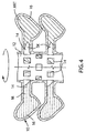
- the still molten metal in the riser passage 12 is drained back to pool P before molten metal M in mold cavities 16 and gate passages 12 solidifies.
- Riser passage 12 is drained by discontinuing the vacuum level in the container by, for example, shutting off vacuum pump PP and opening a vent valve W in the vacuum piping, Figure 2 , communicated to ambient pressure to provide ambient air pressure in the container. Pressure on the molten column in the riser passage 12 is equalized such that the molten metal in the riser passage 12 flows by gravity back to underlying pool P for reuse.
- the gate passages 14 are thereby separated from the now empty riser passage 12. Molten metal is retained in the gate passages 14, at least partially filling them as shown in the left hand side of Figure 4 , by virtue of the centrifugal forces due to rotation of the container 20 (20') and mold 10.
- the molten metal partially filling the gate passages 14 and completely filling the mold cavities 16 is subjected to the ambient (e.g. atmospheric) pressure in the riser passage 12 plus pressure due to centrifugal forces from rotational motion of the container 20 (20') and mold 10 such that the pressure across the gate passages 14 is generally equal regardless of their elevation along the riser passage 12.
- a pressure in the mold cavities 16 at a distance of 5 inches from the center axis of the empty riser passage 12 has been determined to be 22.7 psi in each mold cavity at all elevations along the length (28 inch length) of the riser passage 12.
- feeding pressure is the same across all of the gate passages 14 to improve uniformity of feeding of the mold cavities from top to bottom of the mold 10.
- the mold cavities are completely filled.
- Filling of the mold cavities refers to the flow of molten metal from the riser passage to initially fill the mold cavities. Feeding refers to subsequent supplying of the molten metal from the gate passages 14 to fill voids created by the phase change during solidification and thermal contraction of the metal in mold cavities 16.
- the molten metal residing in the gate passages 14 is available for supply to the mold cavities 16 in response to shrinkage as molten metal therein solidifies while the container 20 (20') is rotated as shown in the right hand side of Figure 4 .
- molten metal from the associated gate passage 14 flows as needed to the mold cavity 16 communicated thereto to counter the shrinkage to produce cast articles ART with improved density (e.g. reduced shrinkage porosity).
- a shrinkage cavity SK typically is formed in the metal solidified in one or more of the gate passages 14 but not in the cast metal article (casting) ART solidified in the mold cavity as illustrated in the right side of Figure 4 .
- FIG. 3 shows the solidified metal in the mold 10 with the skrinkage cavities SK omitted for convenience.
- Porosity due to entrapped gas in the cast articles ART also is reduced as a result of the presence of ambient (e.g. atmospheric) pressure plus centrifugal pressure across all of the gate passages 14 by virtue of the pressure reducing the volume of any entrapped gas void in the metal.
- ambient pressure e.g. atmospheric
- centrifugal pressure across all of the gate passages 14 by virtue of the pressure reducing the volume of any entrapped gas void in the metal.
- a much greater number of cast articles ART can be cast in each mold 10 with little or no shrinkage porosity in practice of the invention.
- Residence time of the fill tube 24 immersed in the molten pool P is reduced in practice of the invention since with proper gate design, the fill tube needs to be in the pool P for only the time required to fill the mold cavities, after which the molten metal in the riser passage 12 can be voided. Solidification of the castings and of the gate passages can occur after the fill tube is removed from the pool. Practice of the invention also reduces exposure of container 20 to radiant heat from the pool P and induction heating from the furnace induction coils, thereby extending container life. Furthermore, solidification time is reduced in practice of the invention since gate passages 14 freeze off (solidify) faster locally at the junction with the empty riser passage 12 than when hot molten metal resides in the riser passage.
- metal yield can be further increased at the expense of a longer casting cycle.
- the cross-section and the length of the gate passages 14 can be reduced and feeding of the molten metal from the riser passage 12 can be maintained until just before the metal in the riser passage begins to solidify. If at this point, the molten metal is voided from the riser passage 12 and mold rotation is continued for a short time to allow the gate passages 14 to solidify, individual castings with very small gates are obtained. Metal yields of 97% have been attained using this technique.
- container 20 (20') with the solidified castings (cast articles ART) in the mold 10 can be moved by arms A (A') to a shakeout table (not shown) followed by removal of the particulate medium 22 and cast articles ART for further post-casting processing.
- a shell mold 10 was made having 84 mold cavities (each to hold 1.27 pounds of steel alloy) about a 28 inch tall riser passage 12 with a 5 inch diameter. Each mold cavity was communicated to the riser passage by a single gate passage 14 having dimensions of 1/2 inch width by 1/2 inch height by 2 inches length. A ceramic fill tube having a length of 8 inches and diameter of 2.5 inches was connected to the bottom of the riser passage and immersed 4 inches below the surface of pool P of the steel alloy. The container 20 was evacuated to 17 inches Hg and rotated at 150 rpm to fill in the mold cavities in 1.8 seconds with rotation continued for 45 seconds after the riser passage was drained to solidify the metal in the mold cavities.
- the steps of causing the molten metal to flow upwardly from the pool P into the riser passage 12 and of rotating the container 20 (20') are conducted concurrently during filling of mold cavities 16 when casting molten metals that are prone to shrinkage problems during solidification. These steps optionally can be conducted sequentially pursuant to another embodiment of the invention with rotation of the container 20 (20') and mold 10 therein being initiated after the molten metal is forced upwardly into the riser passage 12 to fill the mold cavities 16. This embodiment of the invention reduces turbulence in the molten metal flowing into the mold cavities 16.
- the invention is not so limited since the mold can be rotated about an axis of rotation AR" offset from and substantially parallel to a longitudinal axis L'' of the riser passage 12'' of the mold 10" as illustrated in Figures 8A, 8B where like reference numerals double primed are used to designate like features of previous figures.
- Axis AR" corresponds to the longitudinal axis of the fill tube 24" and of the container in which the mold is disposed.
- each mold cavity can include multiple gate passages.
- each of a plurality of mold cavities 216 typically is elongated in the direction of the riser passage 212.
- Each mold cavity 216 is communicated by a plurality (e.g. three shown) of gate passages 214 at different elevations along the riser passage 212 located to insure feeding of molten metal to the relatively thick regions 216a of each mold cavity.
- the relatively thin solidified regions 216b partition the mold cavity into sub-cavities 216c of still molten metal isolated from one another by the thin solidified regions 216b such that sub-cavities 216c behave as individual single-gated mold cavities so to confine still molten metal in the sub-cavities or compartments 216c between the solidified regions 216b and prevent flow back out of the lowermost gate passages 214 of the mold cavities 216.
- the gate passages 214 that are partially filled with molten metal when the riser passage 212 is drained of molten metal will supply still molten metal therein to a respective sub-cavity or compartment 216c in response to shrinkage as molten metal solidifies while the container 20 (20') is rotated as described above.
- the lower gate passages 216" are shown having relatively shorter lengths as compared to those of the intermediate gate passages 214", which have relatively shorter lengths than those of the upper gate passages 214" shown.
- the longitudinal axis LA" of each mold cavity 216" is oriented at an outward acute angle AA" relative to the longitudinal axis L" of the riser passage 212" using different lengths of gate passages 214".
- Figure 7B illustrates a similar mold 210"' where the mold cavities 216''' are not tilted out pursuant to the invention as shown in Figure 7A such that if the riser passage 212"' is voided while most of the molten metal in each mold cavity 216"' remains unsolidified, then the theoretical melt surface SF"' provided by mold rotation will pass through the gate passages 214"' and mold cavities 216"' as illustrated during draining of the riser passage. Areas of the mold cavities 216''' where the theoretical melt surface SF''' passes through will void molten metal and produce defective castings.
- Figure 7A pursuant to an embodiment of the invention overcomes such unwanted voiding of molten metal from the mold cavities.
- Figure 9A illustrates a portion of such a gas impermeable mold 312" that can be used to centrifugally countergravity cast a bullet-shaped mold cavity 316" with molten metal as described above.
- Pressure gradient lines 1.0A, 1.1A, 1.2A, 1.3A, 1.4A are shown representing pressure gradient in atmospheres inside the mold 310" rotating at 300 rpm after the molten metal is voided form the riser passage 312" but while the molten metal is still liquid in mold cavities 316".
- the pressure gradient will cause the molten metal M" to displace gas in each mold cavity 316'' through the associated gate passage 314" as each mold cavity 316" is filled, even from regions of the mold cavity above the gate passage, as long as the gas in the mold cavity 316" has an unobstructed path of ever-decreasing pressure toward the gate passage 314" of that mold cavity 316''.
- Figure 9B illustrates a similar gas impermeable mold cavity 316'" filled with molten metal by conventional gravity pouring (ladling) or conventional (non-centrifugal) countergravity casting not pursuant to the invention, Gas will be trapped in regions of the mold cavity above the gate passage 314"'. For example, an air pocket P''' is present at the top of the mold cavity 316'''.
- Figure 9A pursuant to an embodiment overcomes this problem of entrapped gas.
- the pattern assembly 410 includes a hollow riser passage-forming portion 412 with a top porous cap 426 and connected by gate passage-forming portions 414 to a plurality of mold cavity-forming portions 416.
- the pattern assembly 410 is comprised of a plurality of foam plastic pattern rings 417 adhered together with each ring forming riser passage-forming portion 412 connected by gate passage-forming portions 414 to a plurality of mold cavity-forming portions 416.
- the pattern rings 417 are stacked one top the other and glued together by a suitable adhesive to form the pattern assembly 410.
- the pattern rings 417 can be cut from as-received expanded polystyrene plate stock or molded by conventional expanded foam technique using expandable polystyrene beads.
- the pattern assembly 410 is coated on the exterior with a refractory slurry to form a thermally insulative, gas permeable refractory coating 420 thereon.
- a refractory coating which can be used in practice of the invention is available as Polyshield 3600 available from Borden Chemical Co. This refractory coating comprises mica and quartz refractory material.
- the coating 420 is applied by dipping the pattern assembly 410 in a slurry of the refractory material, draining excess slurry, and drying the slurry overnight to provide a gas permeable refractory coating on exterior surfaces of the pattern assembly having a thickness in the range of 0.010 to 0.020 inch.
- the container 20 with the fugitive pattern assembly 410 can be used in lieu of container 20 and mold 10 of Figures 1-3 in practicing of the method of the invention as described above.
- the molten metal M is forced to flow upwardly from the pool P into hollow riser passage-forming portion 412 of the pattern assembly 410 by virtue of ambient (atmospheric) pressure on the molten metal M and the subambient pressure in the container 20.
- the molten metal advances upwardly progressively destroying and replacing the pattern assembly 410 in the particulate medium 22 to form in-situ a riser passage similar to riser passage 12, gate passages similar to gate passages 14 and mold cavities similar to mold cavities 16 described above.
- Centrifugal pressure will accelerate the movement of the molten metal through the vaporizable pattern to the outside perimeter of the mold cavity formed thereby.
- the cavities will fill from the outside-in such that liquid and gaseous pattern material (e.g. liquid and gaseous styrene) will be displaced toward the riser passage where at least some of it may escape through the gates.
- the molten metal in the riser passage is drained as described above before molten metal in the mold cavities and the gate passages solidifies, leaving the gate passages at least partially filled with molten metal for supply to the mold cavities in response to shrinkage as molten metal therein solidifies while the container is rotated.
- the molten metal in the mold cavities is solidified while rotating the container to form a plurality of individual solidified cast articles in the mold cavities. Rotation of the mold can be terminated after molten metal solidifies in the mold cavities and gate passages.
Landscapes
- Engineering & Computer Science (AREA)
- Mechanical Engineering (AREA)
- Molds, Cores, And Manufacturing Methods Thereof (AREA)
- Casting Support Devices, Ladles, And Melt Control Thereby (AREA)
Applications Claiming Priority (3)
| Application Number | Priority Date | Filing Date | Title |
|---|---|---|---|
| US932847 | 1997-09-18 | ||
| US09/932,847 US6499529B1 (en) | 2001-08-17 | 2001-08-17 | Centrifugal countergravity casting |
| PCT/US2002/025994 WO2003015958A1 (en) | 2001-08-17 | 2002-08-14 | Centrifugal countergravity casting |
Publications (3)
| Publication Number | Publication Date |
|---|---|
| EP1417062A1 EP1417062A1 (en) | 2004-05-12 |
| EP1417062A4 EP1417062A4 (en) | 2005-09-07 |
| EP1417062B1 true EP1417062B1 (en) | 2016-10-19 |
Family
ID=25463048
Family Applications (1)
| Application Number | Title | Priority Date | Filing Date |
|---|---|---|---|
| EP02759373.0A Expired - Lifetime EP1417062B1 (en) | 2001-08-17 | 2002-08-14 | Centrifugal countergravity casting |
Country Status (11)
| Country | Link |
|---|---|
| US (1) | US6499529B1 (https=) |
| EP (1) | EP1417062B1 (https=) |
| JP (1) | JP4678633B2 (https=) |
| KR (1) | KR100947948B1 (https=) |
| CN (1) | CN1260024C (https=) |
| AU (1) | AU2002324714B2 (https=) |
| BR (1) | BR0210315B1 (https=) |
| CA (1) | CA2447994C (https=) |
| MX (1) | MXPA04001426A (https=) |
| RU (1) | RU2278765C2 (https=) |
| WO (1) | WO2003015958A1 (https=) |
Cited By (1)
| Publication number | Priority date | Publication date | Assignee | Title |
|---|---|---|---|---|
| RU2685935C1 (ru) * | 2018-01-09 | 2019-04-23 | Иосиф Исаакович Фейман | Способ изготовления заготовок поршневых колец |
Families Citing this family (38)
| Publication number | Priority date | Publication date | Assignee | Title |
|---|---|---|---|---|
| ITTO20010287A1 (it) * | 2001-03-27 | 2002-09-27 | Teksid Spa | Apparecchiatura di colata per la produzione di getti metallici mediante tecnologia "lost-foam". |
| BR0106345B1 (pt) * | 2001-12-13 | 2009-05-05 | arranjo de mancalização para molde de injeção por centrifugação. | |
| ITBS20030068A1 (it) * | 2003-07-07 | 2005-01-08 | Meccanica Bassi S P A | Banco, conchiglia e procedimento di colata, in particolare per testa cilindri di motore. |
| GB2409423B (en) * | 2003-12-23 | 2007-04-11 | Doncasters Ltd | Metal casting apparatus and method |
| DE112006000461T5 (de) * | 2005-02-22 | 2008-03-13 | Milwaukee School Of Engineering, Milwaukee | Gießverfahren |
| US8820390B2 (en) * | 2011-02-25 | 2014-09-02 | Raytheon Company | Methods and composition for boride distribution in metal matrix composite |
| US20130323522A1 (en) * | 2012-06-05 | 2013-12-05 | General Electric Company | Cast superalloy pressure containment vessel |
| US8701742B2 (en) * | 2012-09-27 | 2014-04-22 | Apple Inc. | Counter-gravity casting of hollow shapes |
| US9802247B1 (en) | 2013-02-15 | 2017-10-31 | Materion Corporation | Systems and methods for counter gravity casting for bulk amorphous alloys |
| US9221096B2 (en) | 2013-03-11 | 2015-12-29 | Ati Properties, Inc. | Centrifugal casting apparatus and method |
| US9364890B2 (en) | 2013-03-11 | 2016-06-14 | Ati Properties, Inc. | Enhanced techniques for centrifugal casting of molten materials |
| US9452473B2 (en) | 2013-03-14 | 2016-09-27 | Pcc Structurals, Inc. | Methods for casting against gravity |
| US8936066B2 (en) * | 2013-03-15 | 2015-01-20 | Metal Casting Technology, Inc. | Method of using a refractory mold |
| CN104043773A (zh) * | 2013-03-15 | 2014-09-17 | 成霖企业股份有限公司 | 易脱模陶瓷铸型的制备、应用方法及其浇铸的铜合金铸件 |
| KR101367200B1 (ko) * | 2013-05-08 | 2014-02-26 | 지정욱 | 이중 주조 방법 및 장치 |
| TWI483758B (zh) * | 2013-09-30 | 2015-05-11 | 復盛應用科技股份有限公司 | 含活性金屬之鋼類高爾夫球桿頭的製造方法 |
| TWI483761B (zh) * | 2013-09-30 | 2015-05-11 | 復盛應用科技股份有限公司 | 不鏽鋼高爾夫球桿頭的製造方法 |
| TWI483762B (zh) * | 2013-10-24 | 2015-05-11 | 復盛應用科技股份有限公司 | 鈦合金高爾夫球桿頭的製造方法 |
| TWI483764B (zh) * | 2013-12-31 | 2015-05-11 | Fusheng Prec Co Ltd | 低密度鋼類高爾夫球木桿頭的製造方法 |
| TWI483763B (zh) * | 2013-12-31 | 2015-05-11 | Fusheng Prec Co Ltd | 高強度鋼類高爾夫球木桿頭的製造方法 |
| TWI483765B (zh) * | 2014-01-03 | 2015-05-11 | Fusheng Prec Co Ltd | 鑄包異材的高爾夫球桿頭製造方法及其殼模 |
| US10668529B1 (en) | 2014-12-16 | 2020-06-02 | Materion Corporation | Systems and methods for processing bulk metallic glass articles using near net shape casting and thermoplastic forming |
| CN106513635B (zh) * | 2016-12-16 | 2019-02-05 | 上海华培动力科技股份有限公司 | 用于耐高温合金真空吸铸工艺的双层空心筒熔模模壳结构 |
| US20200156147A1 (en) | 2017-10-27 | 2020-05-21 | United Technologies Corporation | Countergravity Casting Apparatus and Desulfurization Methods |
| CN107891136B (zh) * | 2017-12-21 | 2020-04-14 | 重庆麦纳昇科技有限公司 | 一种离心铸造机自动控制系统 |
| CN107855487B (zh) * | 2017-12-21 | 2020-04-14 | 重庆麦纳昇科技有限公司 | 一种离心铸造机 |
| CN110871266B (zh) * | 2018-08-31 | 2021-10-29 | 复盛应用科技股份有限公司 | 高尔夫球杆头铸造法 |
| CN109175305A (zh) * | 2018-10-12 | 2019-01-11 | 珠海格力电器股份有限公司 | 一种叶轮铸造工艺及叶轮 |
| CN109128097A (zh) * | 2018-10-17 | 2019-01-04 | 南昌航空大学 | 一种真空差压铸造分级加压凝固开始加压熔体温度方法 |
| CN109909478B (zh) * | 2019-02-25 | 2020-12-22 | 镇江市吉玛铸造科技有限公司 | 一种梯度复合材料刹车盘的制作方法 |
| CA3139661A1 (en) * | 2019-05-09 | 2020-11-12 | Dustin Eplee | Fluidized bed rotational molding |
| US11117292B2 (en) | 2019-05-09 | 2021-09-14 | Dustin Eplee | Fluidized bed rotational molding |
| CN110328351B (zh) * | 2019-08-13 | 2021-06-04 | 西安西工大超晶科技发展有限责任公司 | 一种反重力浇注熔模铸件免水玻璃砂造型的工艺方法 |
| CN112548036A (zh) * | 2021-01-06 | 2021-03-26 | 洛阳佳会机械科技有限公司 | 一种用于消失模离心铸造的生产工艺 |
| CN116140587B (zh) * | 2022-12-14 | 2025-06-27 | 西北工业大学 | 一种多功能反重力铸造设备及铸造方法 |
| CN117444177A (zh) * | 2023-11-02 | 2024-01-26 | 西北工业大学 | 一种高效实现高温合金多功能反重力铸造装置 |
| CN117161358B (zh) * | 2023-11-03 | 2024-01-30 | 无锡永兴机械制造有限公司 | 一种叶轮的铸造装置及其铸造工艺 |
| CN119634672A (zh) * | 2024-11-29 | 2025-03-18 | 陕西柴油机重工有限公司 | 一种砂型铸造薄壁铸件的生产方法 |
Family Cites Families (20)
| Publication number | Priority date | Publication date | Assignee | Title |
|---|---|---|---|---|
| NL15051C (https=) | 1923-08-09 | |||
| US2497160A (en) | 1938-10-08 | 1950-02-14 | Fejmert Erik Valdemar | Machine for manufacturing hollow bodies of plastic material |
| US2450832A (en) | 1943-07-05 | 1948-10-05 | Theodore C Kuhlman | Centrifugal casting |
| US2450755A (en) | 1944-06-10 | 1948-10-05 | Allis Chalmers Mfg Co | Method of centrifugal casting |
| US2997756A (en) | 1956-07-17 | 1961-08-29 | Griffin Wheel Co | Method and apparatus for casting ingots |
| FR1587403A (https=) | 1968-09-17 | 1970-03-20 | Lajoye Pierre | |
| NL6905546A (https=) | 1969-02-28 | 1970-09-01 | ||
| US3900064A (en) | 1972-12-04 | 1975-08-19 | Hitchiner Manufacturing Co | Metal casting |
| US3863706A (en) | 1972-12-04 | 1975-02-04 | Hitchiner Manufacturing Co | Metal casting |
| FR2296483A1 (fr) | 1975-01-02 | 1976-07-30 | Lajoye Pierre | Procede pour la fusion et la coulee centrifuge sous vide de metaux, dispositif pour sa mise en oeuvre et pieces obtenues |
| US4392805A (en) | 1980-10-31 | 1983-07-12 | Golyak Oleg L | Centrifugal casting apparatus |
| GB8301616D0 (en) | 1983-01-21 | 1983-02-23 | Steel Castings Res | Ceramic shell moulds |
| US4589466A (en) | 1984-02-27 | 1986-05-20 | Hitchiner Manufacturing Co., Inc. | Metal casting |
| US4787434A (en) * | 1986-12-29 | 1988-11-29 | Brunswick Corporation | Vacuum lift foam filled casting system |
| US4791977A (en) * | 1987-05-07 | 1988-12-20 | Metal Casting Technology, Inc. | Countergravity metal casting apparatus and process |
| US4874029A (en) | 1988-05-09 | 1989-10-17 | General Motors Corporation | Countergravity casting process and apparatus using destructible patterns suspended in an inherently unstable mass of particulate mold material |
| US5179995A (en) | 1989-07-17 | 1993-01-19 | Limb Stanley R | Combination vacuum assist centrifugal casting apparatus and method |
| US5069271A (en) | 1990-09-06 | 1991-12-03 | Hitchiner Corporation | Countergravity casting using particulate supported thin walled investment shell mold |
| DE9416731U1 (de) | 1994-10-18 | 1995-01-12 | Sulzer-Escher Wyss Gmbh, 88212 Ravensburg | Stoffauflauf für eine Papiermaschine |
| JP2000225455A (ja) * | 1999-02-03 | 2000-08-15 | Toyota Motor Corp | 鋳鉄の鋳造方法及びその装置 |
-
2001
- 2001-08-17 US US09/932,847 patent/US6499529B1/en not_active Expired - Lifetime
-
2002
- 2002-08-14 AU AU2002324714A patent/AU2002324714B2/en not_active Ceased
- 2002-08-14 BR BRPI0210315-0A patent/BR0210315B1/pt not_active IP Right Cessation
- 2002-08-14 WO PCT/US2002/025994 patent/WO2003015958A1/en not_active Ceased
- 2002-08-14 EP EP02759373.0A patent/EP1417062B1/en not_active Expired - Lifetime
- 2002-08-14 KR KR1020047002249A patent/KR100947948B1/ko not_active Expired - Lifetime
- 2002-08-14 JP JP2003520503A patent/JP4678633B2/ja not_active Expired - Lifetime
- 2002-08-14 CN CNB02813351XA patent/CN1260024C/zh not_active Expired - Fee Related
- 2002-08-14 CA CA002447994A patent/CA2447994C/en not_active Expired - Lifetime
- 2002-08-14 RU RU2004107898/02A patent/RU2278765C2/ru active
- 2002-08-14 MX MXPA04001426A patent/MXPA04001426A/es active IP Right Grant
Cited By (1)
| Publication number | Priority date | Publication date | Assignee | Title |
|---|---|---|---|---|
| RU2685935C1 (ru) * | 2018-01-09 | 2019-04-23 | Иосиф Исаакович Фейман | Способ изготовления заготовок поршневых колец |
Also Published As
| Publication number | Publication date |
|---|---|
| WO2003015958A1 (en) | 2003-02-27 |
| CA2447994C (en) | 2009-06-23 |
| HK1067333A1 (en) | 2005-04-08 |
| RU2004107898A (ru) | 2005-06-10 |
| EP1417062A1 (en) | 2004-05-12 |
| KR20040030112A (ko) | 2004-04-08 |
| JP4678633B2 (ja) | 2011-04-27 |
| CN1260024C (zh) | 2006-06-21 |
| CA2447994A1 (en) | 2003-02-27 |
| US6499529B1 (en) | 2002-12-31 |
| EP1417062A4 (en) | 2005-09-07 |
| KR100947948B1 (ko) | 2010-03-15 |
| BR0210315B1 (pt) | 2011-09-06 |
| CN1522182A (zh) | 2004-08-18 |
| JP2004538152A (ja) | 2004-12-24 |
| RU2278765C2 (ru) | 2006-06-27 |
| AU2002324714B2 (en) | 2007-10-25 |
| MXPA04001426A (es) | 2004-06-03 |
| BR0210315A (pt) | 2004-09-14 |
Similar Documents
| Publication | Publication Date | Title |
|---|---|---|
| EP1417062B1 (en) | Centrifugal countergravity casting | |
| AU2002324714A1 (en) | Centrifugal countergravity casting | |
| JP2004538152A5 (https=) | ||
| US4733714A (en) | Method of and apparatus for casting | |
| EP0578922B1 (en) | Countergravity casting apparatus and method | |
| US4874029A (en) | Countergravity casting process and apparatus using destructible patterns suspended in an inherently unstable mass of particulate mold material | |
| CA2049228C (en) | Countergravity casting using particulate supported thin walled investment shell mold | |
| WO2007100673A2 (en) | Composite mold with fugitive metal backup | |
| CN1040529A (zh) | 反重力铸造方法及其设备 | |
| US6453976B1 (en) | Lost foam countergravity casting | |
| EP0356624A2 (en) | Vacuum countergravity casting apparatus and method with backflow valve | |
| WO2019217270A1 (en) | Casting system | |
| US6019158A (en) | Investment casting using pour cup reservoir with inverted melt feed gate | |
| GB2187984A (en) | Casting molten metal | |
| EP1101551B1 (en) | Investment casting using melt reservoir loop | |
| US6070644A (en) | Investment casting using pressure cap sealable on gas permeable investment mold | |
| HK1067333B (en) | Centrifugal countergravity casting | |
| JP2004306044A (ja) | 精密鋳造装置およびこれを用いる精密鋳造方法 | |
| WO2002102532A2 (en) | Investment casting with improved melt feeding | |
| JPH0466256A (ja) | 有底部品の鋳造方法及び鋳造装置 |
Legal Events
| Date | Code | Title | Description |
|---|---|---|---|
| PUAI | Public reference made under article 153(3) epc to a published international application that has entered the european phase |
Free format text: ORIGINAL CODE: 0009012 |
|
| 17P | Request for examination filed |
Effective date: 20031121 |
|
| AK | Designated contracting states |
Kind code of ref document: A1 Designated state(s): AT BE BG CH CY CZ DE DK EE ES FI FR GB GR IE IT LI LU MC NL PT SE SK TR |
|
| A4 | Supplementary search report drawn up and despatched |
Effective date: 20050722 |
|
| RIC1 | Information provided on ipc code assigned before grant |
Ipc: 7B 22D 18/06 B Ipc: 7B 22D 13/00 A Ipc: 7B 22D 18/04 B Ipc: 7B 22D 13/04 B |
|
| 17Q | First examination report despatched |
Effective date: 20061024 |
|
| GRAP | Despatch of communication of intention to grant a patent |
Free format text: ORIGINAL CODE: EPIDOSNIGR1 |
|
| INTG | Intention to grant announced |
Effective date: 20160517 |
|
| GRAS | Grant fee paid |
Free format text: ORIGINAL CODE: EPIDOSNIGR3 |
|
| GRAA | (expected) grant |
Free format text: ORIGINAL CODE: 0009210 |
|
| AK | Designated contracting states |
Kind code of ref document: B1 Designated state(s): AT BE BG CH CY CZ DE DK EE ES FI FR GB GR IE IT LI LU MC NL PT SE SK TR |
|
| REG | Reference to a national code |
Ref country code: GB Ref legal event code: FG4D |
|
| REG | Reference to a national code |
Ref country code: CH Ref legal event code: EP |
|
| REG | Reference to a national code |
Ref country code: AT Ref legal event code: REF Ref document number: 837901 Country of ref document: AT Kind code of ref document: T Effective date: 20161115 |
|
| REG | Reference to a national code |
Ref country code: IE Ref legal event code: FG4D |
|
| REG | Reference to a national code |
Ref country code: DE Ref legal event code: R096 Ref document number: 60248425 Country of ref document: DE |
|
| REG | Reference to a national code |
Ref country code: NL Ref legal event code: MP Effective date: 20161019 |
|
| REG | Reference to a national code |
Ref country code: AT Ref legal event code: MK05 Ref document number: 837901 Country of ref document: AT Kind code of ref document: T Effective date: 20161019 |
|
| PG25 | Lapsed in a contracting state [announced via postgrant information from national office to epo] |
Ref country code: GR Free format text: LAPSE BECAUSE OF FAILURE TO SUBMIT A TRANSLATION OF THE DESCRIPTION OR TO PAY THE FEE WITHIN THE PRESCRIBED TIME-LIMIT Effective date: 20170120 Ref country code: SE Free format text: LAPSE BECAUSE OF FAILURE TO SUBMIT A TRANSLATION OF THE DESCRIPTION OR TO PAY THE FEE WITHIN THE PRESCRIBED TIME-LIMIT Effective date: 20161019 |
|
| PG25 | Lapsed in a contracting state [announced via postgrant information from national office to epo] |
Ref country code: PT Free format text: LAPSE BECAUSE OF FAILURE TO SUBMIT A TRANSLATION OF THE DESCRIPTION OR TO PAY THE FEE WITHIN THE PRESCRIBED TIME-LIMIT Effective date: 20170220 Ref country code: FI Free format text: LAPSE BECAUSE OF FAILURE TO SUBMIT A TRANSLATION OF THE DESCRIPTION OR TO PAY THE FEE WITHIN THE PRESCRIBED TIME-LIMIT Effective date: 20161019 Ref country code: AT Free format text: LAPSE BECAUSE OF FAILURE TO SUBMIT A TRANSLATION OF THE DESCRIPTION OR TO PAY THE FEE WITHIN THE PRESCRIBED TIME-LIMIT Effective date: 20161019 Ref country code: NL Free format text: LAPSE BECAUSE OF FAILURE TO SUBMIT A TRANSLATION OF THE DESCRIPTION OR TO PAY THE FEE WITHIN THE PRESCRIBED TIME-LIMIT Effective date: 20161019 Ref country code: BE Free format text: LAPSE BECAUSE OF FAILURE TO SUBMIT A TRANSLATION OF THE DESCRIPTION OR TO PAY THE FEE WITHIN THE PRESCRIBED TIME-LIMIT Effective date: 20161019 Ref country code: ES Free format text: LAPSE BECAUSE OF FAILURE TO SUBMIT A TRANSLATION OF THE DESCRIPTION OR TO PAY THE FEE WITHIN THE PRESCRIBED TIME-LIMIT Effective date: 20161019 |
|
| REG | Reference to a national code |
Ref country code: DE Ref legal event code: R097 Ref document number: 60248425 Country of ref document: DE |
|
| PG25 | Lapsed in a contracting state [announced via postgrant information from national office to epo] |
Ref country code: SK Free format text: LAPSE BECAUSE OF FAILURE TO SUBMIT A TRANSLATION OF THE DESCRIPTION OR TO PAY THE FEE WITHIN THE PRESCRIBED TIME-LIMIT Effective date: 20161019 Ref country code: EE Free format text: LAPSE BECAUSE OF FAILURE TO SUBMIT A TRANSLATION OF THE DESCRIPTION OR TO PAY THE FEE WITHIN THE PRESCRIBED TIME-LIMIT Effective date: 20161019 Ref country code: DK Free format text: LAPSE BECAUSE OF FAILURE TO SUBMIT A TRANSLATION OF THE DESCRIPTION OR TO PAY THE FEE WITHIN THE PRESCRIBED TIME-LIMIT Effective date: 20161019 |
|
| PLBE | No opposition filed within time limit |
Free format text: ORIGINAL CODE: 0009261 |
|
| REG | Reference to a national code |
Ref country code: FR Ref legal event code: PLFP Year of fee payment: 16 |
|
| STAA | Information on the status of an ep patent application or granted ep patent |
Free format text: STATUS: NO OPPOSITION FILED WITHIN TIME LIMIT |
|
| PG25 | Lapsed in a contracting state [announced via postgrant information from national office to epo] |
Ref country code: BG Free format text: LAPSE BECAUSE OF FAILURE TO SUBMIT A TRANSLATION OF THE DESCRIPTION OR TO PAY THE FEE WITHIN THE PRESCRIBED TIME-LIMIT Effective date: 20170119 |
|
| 26N | No opposition filed |
Effective date: 20170720 |
|
| REG | Reference to a national code |
Ref country code: CH Ref legal event code: PL |
|
| PG25 | Lapsed in a contracting state [announced via postgrant information from national office to epo] |
Ref country code: MC Free format text: LAPSE BECAUSE OF FAILURE TO SUBMIT A TRANSLATION OF THE DESCRIPTION OR TO PAY THE FEE WITHIN THE PRESCRIBED TIME-LIMIT Effective date: 20161019 |
|
| PG25 | Lapsed in a contracting state [announced via postgrant information from national office to epo] |
Ref country code: CH Free format text: LAPSE BECAUSE OF NON-PAYMENT OF DUE FEES Effective date: 20170831 Ref country code: LI Free format text: LAPSE BECAUSE OF NON-PAYMENT OF DUE FEES Effective date: 20170831 |
|
| REG | Reference to a national code |
Ref country code: IE Ref legal event code: MM4A |
|
| PG25 | Lapsed in a contracting state [announced via postgrant information from national office to epo] |
Ref country code: LU Free format text: LAPSE BECAUSE OF NON-PAYMENT OF DUE FEES Effective date: 20170814 |
|
| PG25 | Lapsed in a contracting state [announced via postgrant information from national office to epo] |
Ref country code: IE Free format text: LAPSE BECAUSE OF NON-PAYMENT OF DUE FEES Effective date: 20170814 |
|
| REG | Reference to a national code |
Ref country code: FR Ref legal event code: PLFP Year of fee payment: 17 |
|
| PG25 | Lapsed in a contracting state [announced via postgrant information from national office to epo] |
Ref country code: CY Free format text: LAPSE BECAUSE OF NON-PAYMENT OF DUE FEES Effective date: 20161019 |
|
| PG25 | Lapsed in a contracting state [announced via postgrant information from national office to epo] |
Ref country code: TR Free format text: LAPSE BECAUSE OF FAILURE TO SUBMIT A TRANSLATION OF THE DESCRIPTION OR TO PAY THE FEE WITHIN THE PRESCRIBED TIME-LIMIT Effective date: 20161019 |
|
| PGFP | Annual fee paid to national office [announced via postgrant information from national office to epo] |
Ref country code: FR Payment date: 20200825 Year of fee payment: 19 Ref country code: DE Payment date: 20200827 Year of fee payment: 19 Ref country code: GB Payment date: 20200827 Year of fee payment: 19 Ref country code: CZ Payment date: 20200819 Year of fee payment: 19 |
|
| PGFP | Annual fee paid to national office [announced via postgrant information from national office to epo] |
Ref country code: IT Payment date: 20200821 Year of fee payment: 19 |
|
| REG | Reference to a national code |
Ref country code: DE Ref legal event code: R119 Ref document number: 60248425 Country of ref document: DE |
|
| GBPC | Gb: european patent ceased through non-payment of renewal fee |
Effective date: 20210814 |
|
| PG25 | Lapsed in a contracting state [announced via postgrant information from national office to epo] |
Ref country code: CZ Free format text: LAPSE BECAUSE OF NON-PAYMENT OF DUE FEES Effective date: 20210814 |
|
| PG25 | Lapsed in a contracting state [announced via postgrant information from national office to epo] |
Ref country code: IT Free format text: LAPSE BECAUSE OF NON-PAYMENT OF DUE FEES Effective date: 20210814 Ref country code: GB Free format text: LAPSE BECAUSE OF NON-PAYMENT OF DUE FEES Effective date: 20210814 Ref country code: FR Free format text: LAPSE BECAUSE OF NON-PAYMENT OF DUE FEES Effective date: 20210831 Ref country code: DE Free format text: LAPSE BECAUSE OF NON-PAYMENT OF DUE FEES Effective date: 20220301 |