EP1416624B1 - Method and control system for controlling electric motors - Google Patents
Method and control system for controlling electric motors Download PDFInfo
- Publication number
- EP1416624B1 EP1416624B1 EP03016488.3A EP03016488A EP1416624B1 EP 1416624 B1 EP1416624 B1 EP 1416624B1 EP 03016488 A EP03016488 A EP 03016488A EP 1416624 B1 EP1416624 B1 EP 1416624B1
- Authority
- EP
- European Patent Office
- Prior art keywords
- relay
- voltage
- windings
- motor
- sensed
- Prior art date
- Legal status (The legal status is an assumption and is not a legal conclusion. Google has not performed a legal analysis and makes no representation as to the accuracy of the status listed.)
- Expired - Lifetime
Links
- 238000000034 method Methods 0.000 title description 5
- 238000004804 winding Methods 0.000 claims description 32
- 239000004020 conductor Substances 0.000 claims 1
- 241000630329 Scomberesox saurus saurus Species 0.000 description 4
- 230000006378 damage Effects 0.000 description 4
- 238000012544 monitoring process Methods 0.000 description 2
- 230000005355 Hall effect Effects 0.000 description 1
- 208000027418 Wounds and injury Diseases 0.000 description 1
- 230000015572 biosynthetic process Effects 0.000 description 1
- 230000001419 dependent effect Effects 0.000 description 1
- 238000006073 displacement reaction Methods 0.000 description 1
- 238000010438 heat treatment Methods 0.000 description 1
- 208000014674 injury Diseases 0.000 description 1
- 239000000463 material Substances 0.000 description 1
- 238000002844 melting Methods 0.000 description 1
- 230000008018 melting Effects 0.000 description 1
- 230000007935 neutral effect Effects 0.000 description 1
- 238000013021 overheating Methods 0.000 description 1
- XLYOFNOQVPJJNP-UHFFFAOYSA-N water Substances O XLYOFNOQVPJJNP-UHFFFAOYSA-N 0.000 description 1
Images

Classifications
-
- H—ELECTRICITY
- H02—GENERATION; CONVERSION OR DISTRIBUTION OF ELECTRIC POWER
- H02H—EMERGENCY PROTECTIVE CIRCUIT ARRANGEMENTS
- H02H7/00—Emergency protective circuit arrangements specially adapted for specific types of electric machines or apparatus or for sectionalised protection of cable or line systems, and effecting automatic switching in the event of an undesired change from normal working conditions
- H02H7/08—Emergency protective circuit arrangements specially adapted for specific types of electric machines or apparatus or for sectionalised protection of cable or line systems, and effecting automatic switching in the event of an undesired change from normal working conditions for dynamo-electric motors
- H02H7/0833—Emergency protective circuit arrangements specially adapted for specific types of electric machines or apparatus or for sectionalised protection of cable or line systems, and effecting automatic switching in the event of an undesired change from normal working conditions for dynamo-electric motors for electric motors with control arrangements
- H02H7/0844—Fail safe control, e.g. by comparing control signal and controlled current, isolating motor on commutation error
-
- H—ELECTRICITY
- H02—GENERATION; CONVERSION OR DISTRIBUTION OF ELECTRIC POWER
- H02P—CONTROL OR REGULATION OF ELECTRIC MOTORS, ELECTRIC GENERATORS OR DYNAMO-ELECTRIC CONVERTERS; CONTROLLING TRANSFORMERS, REACTORS OR CHOKE COILS
- H02P7/00—Arrangements for regulating or controlling the speed or torque of electric DC motors
- H02P7/03—Arrangements for regulating or controlling the speed or torque of electric DC motors for controlling the direction of rotation of DC motors
Definitions
- the invention relates to a method and control system for controlling electric motors, especially motors carrying relatively strong current.
- Such motors are widely used for the operation of ship thrusters where it is also particularly important to assure reliable operation.
- the object of the invention is to provide a method for controlling electric motors and a control system for electric motors which eliminate the problems of the aforementioned type, and this is achieved by the system as disclosed in claim 1.
- Document EP0651489 discloses a control system for an electric motor (M), wherein the control system comprises an operating relay having first (C1) and second (C2) relay windings, each with respective normally open and a normally closed relay contacts.
- Fig. 1 indicates, inter alia, an electric motor comprising a rotor or armature 9 and field coils or field magnets M.
- the motor is a direct-current motor whose rotor 9 and field magnet or magnets M are connected via an operating relay 10, a control means 13, which in the illustrated case consists of a joystick with spring return, wires, a safety fuse 14 and a switch 12, to a power source 11, in the illustrated case a battery.
- the operating relay 10 is of a type that comprises a first relay winding A1 and a second relay winding B1, each comprising two respective relay contacts A and B respectively. In the drawing, the circuit connection is shown when non-energised or in so-called open position.
- the centre position or neutral position of the joystick 13 and one of the poles of the armature 9 are connected to the negative terminal of the battery 11.
- the circuit is ready for operation.
- the joystick 13 is moved across to the left of the figure, contact is made between a wire 4 and a wire 1 in the first relay winding A1 so that a circuit is formed through the winding to the wire 3 and via the safety fuse 14 and the switch 12 to the positive terminal of the battery 11, and the relay winding is energised so that one of the relay contacts A is opened or broken and the other is closed or made.
- the direction of current is defined as a positive to negative direction.
- the current flows through the field coils or field magnets M, then through the closed relay contact B and the armature 9 and back to the negative terminal of the battery 11.
- the current is connected through the relay winding B1 so that the relay contacts are opened and closed respectively via the closed contact to the opposite side of the field coils or field magnets M, according to the sequence described above, through the now closed relay contact A and to the armature 9. Since the field magnets are now excited in the opposite direction, the motor will rotate in the opposite direction.
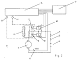
- Fig. 2 shows a circuit connection or control system which for the most part is similar to the connection in Fig. 1 , but which has been modified so that a far more reliable operation is provided according to the invention.
- a safety function unit 15 which is provided with terminals for connection to the control means 13, the relay windings A1 and B1, optionally a thermoswitch 16 connected to the motor armature 9 or simply arranged internally in the motor and provides controlling current or displacement voltage to the control system, and two terminals S1 and S2 which via indicated broken lines are connected to the open, non-energised relay contacts A and B respectively or another suitable point in the motor which has a varying voltage or current depending on operation or non-operation of the motor.
- the control means 13 may comprise one or more of a number of operating devices such as a joystick, a touch panel, buttons and/or switches, to provide corresponding current control to the motor and the operating relay 10 as described above.
- This applied signal is compared with the voltage at the respective relay windings A1 and B1, i.e., the control signal at the magnet coils of the relay.
- On position is only accepted by the unit 15 or the control system when the respective relay contact A or B and magnet winding A1 or B1 also have voltage applied thereto.
- a suitable method for determining whether the operating relay contacts are in the on position is, for example, that voltages are measured and compared, the drawing of current is measured, the Hall effect is measured, the rotational speed of the motor is measured, frequencies in cables are measured or the actual mechanical position of the relay contacts is determined using a switch or another sensor etc. All these options and possibly other options for determining whether the operating relay contacts are energised are within the scope of the invention and represent technically obvious options or alternatives.
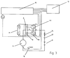
- Fig. 3 shows another variant of the control system according to the invention which comprises safety functions for monitoring the voltage to the motor 9.
- the system in Fig. 3 is shown and described as a separate system, although it could have been incorporated into the system in Fig. 2 .
- Fig. 3 shows the safety function unit 15 equipped with a terminal SV which via a wire indicated in a broken line is connected to the wire 3 between the relay windings.
- the problem on which this variant of the invention is based is that at low supply voltage, the relays A and B could fail with a subsequent risk of burning and uncontrollable operation of the electric motor and thruster.
- the reason for the burning of the contacts at low voltage is that even at low output voltage (battery voltage), the thruster motor will draw substantial amounts of current. This current will lead to a voltage drop in cables or wires and the battery when the motor is running. If the output voltage is too low, this will cause the relays to fail. When the relays fail, the voltage to the motor will be cut off and the voltage rises again to its starting-up point. This is repeated at a frequency which, because of the arc formation, quickly results in overheating and melting of the contacts on the operating relay of the motor. The relay contacts A or B might then become locked in the on position.
- One solution to this problem may be to ensure that the relay cannot cut in and out as mentioned above at a fairly high frequency.
- the control system monitors the voltage applied to the relay coils A1 and B1 and if the voltage is too low, the power supply to the relay windings of the operating relay is cut, whereupon a delay device is activated before the next feed or application of voltage to the same or to the opposite side of the relay windings A1 and B1 once the voltage is above the threshold value again.
- the operator or the skipper or user will then register that the voltage is too low in that the thruster performs with a distinct low-frequency pulsating output.
- the contacts of the operating relay are thus not damaged because of the low frequency and the thus limited heating of the contact faces, and necessary measures can be taken before greater damage is done.
- the application of voltage to the operating relay coils will not be fed to a relay winding if the voltage is measured to be below the threshold value.
- control system in fact provides is to reduce the possibility of damage to the relay contact faces caused by low voltage during operation, and that in the event that the relay is nevertheless in the energised, operational position without the user or skipper having given a signal for this, that the system, on the application of current to one or both of the relay windings A1 and B1, ensures that the relay contacts A and B are put in the same position, i.e., the on position at the same time in order to stop the motor because the circuit is broken when both relay contacts are in the same position.
Landscapes
- Engineering & Computer Science (AREA)
- Power Engineering (AREA)
- Control Of Electric Motors In General (AREA)
- Control Of Multiple Motors (AREA)
- Control Of Ac Motors In General (AREA)
Applications Claiming Priority (2)
| Application Number | Priority Date | Filing Date | Title |
|---|---|---|---|
| NO20025207A NO316049B1 (no) | 2002-10-30 | 2002-10-30 | Fremgangsmåte og styresystem for styring av elektromotorer |
| NO20025207 | 2002-10-30 |
Publications (2)
| Publication Number | Publication Date |
|---|---|
| EP1416624A1 EP1416624A1 (en) | 2004-05-06 |
| EP1416624B1 true EP1416624B1 (en) | 2016-06-22 |
Family
ID=19914134
Family Applications (1)
| Application Number | Title | Priority Date | Filing Date |
|---|---|---|---|
| EP03016488.3A Expired - Lifetime EP1416624B1 (en) | 2002-10-30 | 2003-07-22 | Method and control system for controlling electric motors |
Country Status (4)
| Country | Link |
|---|---|
| US (1) | US7359166B2 (da) |
| EP (1) | EP1416624B1 (da) |
| DK (1) | DK1416624T3 (da) |
| NO (1) | NO316049B1 (da) |
Families Citing this family (3)
| Publication number | Priority date | Publication date | Assignee | Title |
|---|---|---|---|---|
| US9893223B2 (en) | 2010-11-16 | 2018-02-13 | Suncore Photovoltaics, Inc. | Solar electricity generation system |
| DE102011089812A1 (de) * | 2011-12-23 | 2013-06-27 | Richard Ag | Schaltvorrichtung für ein elektrisch angetriebenes Fahrzeug und Elektrofahrzeug |
| CN107143964B (zh) * | 2016-03-01 | 2021-01-12 | 珠海格力电器股份有限公司 | 用于启动空调的启动电路和空调器 |
Family Cites Families (23)
| Publication number | Priority date | Publication date | Assignee | Title |
|---|---|---|---|---|
| US3671834A (en) * | 1970-03-09 | 1972-06-20 | Westinghouse Air Brake Co | Reverser protective circuit |
| US3656023A (en) * | 1970-09-21 | 1972-04-11 | Joseph M Hadfield | Protective circuit |
| US3898527A (en) * | 1974-06-26 | 1975-08-05 | Lennox Ind Inc | Motor protection apparatus and method |
| US3911341A (en) * | 1974-09-20 | 1975-10-07 | Eltra Corp | Switching type motor speed control |
| DE2449395A1 (de) | 1974-10-17 | 1976-04-22 | Se Fahrzeugwerke Gmbh | Schalteinrichtung zur umschaltung der drehrichtung von elektromotoren |
| US4027202A (en) * | 1975-12-19 | 1977-05-31 | Robertshaw Controls Company | Voltage protection circuit |
| US4151575A (en) * | 1977-03-07 | 1979-04-24 | Hogue Maurice A | Motor protective device |
| DE3002232A1 (de) * | 1980-01-23 | 1981-07-30 | Robert Bosch Gmbh, 7000 Stuttgart | Schalteinrichtung fuer elektrische andrehvorrichtungen fuer brennkraftmaschinen |
| DE3135888A1 (de) * | 1981-09-10 | 1983-03-24 | Robert Bosch Gmbh, 7000 Stuttgart | Sicherheitseinrichtung fuer eine elektrische stellvorrichtung |
| US4638850A (en) * | 1984-02-28 | 1987-01-27 | A. T. Newell Co. Inc. | Electronic thermostat |
| IT1225113B (it) * | 1988-07-07 | 1990-11-02 | Procond Elettronica Spa | Dispositivo di controllo per motore elettrico universale. |
| JP2715473B2 (ja) * | 1988-09-19 | 1998-02-18 | アイシン精機株式会社 | 電動パワーステアリング装置のフエイルセイフ装置 |
| DE3904771C1 (en) * | 1989-02-17 | 1990-06-07 | Leopold Kostal Gmbh & Co Kg, 5880 Luedenscheid, De | Switch arrangement for the actuators of vehicle seat parts |
| JPH02216726A (ja) | 1989-02-17 | 1990-08-29 | Matsushita Electric Works Ltd | 再投入遅延リレー |
| US5189412A (en) * | 1990-05-11 | 1993-02-23 | Hunter Fan Company | Remote control for a ceiling fan |
| JP2721056B2 (ja) | 1991-08-29 | 1998-03-04 | 株式会社クボタ | 電動アクチュエータの非常停止装置 |
| JP2594573Y2 (ja) | 1993-11-02 | 1999-04-26 | 住友電装株式会社 | リレーの異常検知装置 |
| US5661625A (en) * | 1995-11-14 | 1997-08-26 | Yang; Tai-Her | Circuit device for unstable power source transient state compensation and low voltage cutoff protection of an active controller component |
| JP2894487B2 (ja) | 1996-11-11 | 1999-05-24 | 茨城県 | 電動走行車用制御装置および電動走行車 |
| US6234100B1 (en) * | 1998-09-03 | 2001-05-22 | The Talaria Company, Llc | Stick control system for waterjet boats |
| US6169648B1 (en) * | 1999-04-09 | 2001-01-02 | Texas Instruments Incorporated | Electronic motor protection system |
| DE19954460C2 (de) * | 1999-11-12 | 2002-02-28 | Pilz Gmbh & Co | Sicherheitsschaltgerät zum Ein- und sicheren Ausschalten eines elektrischen Verbrauchers, insbesondere einer elektrisch angetriebenen Maschine |
| JP2002175750A (ja) * | 2000-12-08 | 2002-06-21 | Toyota Motor Corp | リレーの溶着検出装置 |
-
2002
- 2002-10-30 NO NO20025207A patent/NO316049B1/no not_active IP Right Cessation
-
2003
- 2003-07-11 US US10/618,265 patent/US7359166B2/en not_active Expired - Lifetime
- 2003-07-22 EP EP03016488.3A patent/EP1416624B1/en not_active Expired - Lifetime
- 2003-07-22 DK DK03016488.3T patent/DK1416624T3/da active
Also Published As
| Publication number | Publication date |
|---|---|
| US20040085695A1 (en) | 2004-05-06 |
| US7359166B2 (en) | 2008-04-15 |
| DK1416624T3 (da) | 2016-09-19 |
| NO20025207A (no) | 2003-12-01 |
| NO20025207D0 (no) | 2002-10-30 |
| NO316049B1 (no) | 2003-12-01 |
| EP1416624A1 (en) | 2004-05-06 |
Similar Documents
| Publication | Publication Date | Title |
|---|---|---|
| CN1589516A (zh) | 开关装置的控制与保护模块 | |
| GB2400990A (en) | Braking device for an electric motor | |
| JP2014527395A (ja) | 分離型巻線モータ用の始動器装置、システムおよび/または方法 | |
| US4942346A (en) | Circuit for controlling rotational direction and rotational speed of an electric motor | |
| US4320328A (en) | Apparatus for full voltage start of vibratory excitors | |
| US3424919A (en) | Remote control system for electrical apparatus | |
| DK1416624T3 (da) | Fremgangsmåde og styresystem til styring af elektriske motorer | |
| US4243920A (en) | Control device for monitoring machines driving revolving devices and method for operating the device | |
| JPH11206182A (ja) | モータ駆動装置及びパワーウインド装置 | |
| EP0777029A1 (en) | A control device for an electrical window regulator for motor vehicles | |
| CA1173104A (en) | Instant reverse control circuit for a single phase motor | |
| US4158158A (en) | D.C. controller for battery powered electric motor | |
| JPWO2024154475A5 (da) | ||
| US6465976B1 (en) | Controlling device for DC motor speed variation | |
| EP0036744B1 (en) | Fail-safe system for pulse-controlled three-terminal d.c. motor | |
| US5654613A (en) | Over drive control apparatus of direct current series motor | |
| US20080111510A1 (en) | Windscreen Wiper Comprising a Protection Device for the Electric Motor Thereof | |
| US2140564A (en) | Motor control | |
| US1951835A (en) | Motor and system of controlling the same | |
| US7126307B2 (en) | Interface circuit for actuating an electrical device and circuit arrangement for actuating an electric motor therewith | |
| JP2001086637A (ja) | 車両の電源確保装置及び方法 | |
| US1264992A (en) | Motor control. | |
| SU1005238A2 (ru) | Устройство дл защиты от неполнофазных режимов работы трехфазной электрической сети | |
| JP4041981B2 (ja) | 駆動装置 | |
| US1196124A (en) | Walter |
Legal Events
| Date | Code | Title | Description |
|---|---|---|---|
| PUAI | Public reference made under article 153(3) epc to a published international application that has entered the european phase |
Free format text: ORIGINAL CODE: 0009012 |
|
| 17P | Request for examination filed |
Effective date: 20030722 |
|
| AK | Designated contracting states |
Kind code of ref document: A1 Designated state(s): AT BE BG CH CY CZ DE DK EE ES FI FR GB GR HU IE IT LI LU MC NL PT RO SE SI SK TR |
|
| AX | Request for extension of the european patent |
Extension state: AL LT LV MK |
|
| AKX | Designation fees paid |
Designated state(s): AT BE BG CH CY CZ DE DK EE ES FI FR GB GR HU IE IT LI LU MC NL PT RO SE SI SK TR |
|
| 17Q | First examination report despatched |
Effective date: 20071030 |
|
| GRAP | Despatch of communication of intention to grant a patent |
Free format text: ORIGINAL CODE: EPIDOSNIGR1 |
|
| INTG | Intention to grant announced |
Effective date: 20160311 |
|
| GRAS | Grant fee paid |
Free format text: ORIGINAL CODE: EPIDOSNIGR3 |
|
| GRAP | Despatch of communication of intention to grant a patent |
Free format text: ORIGINAL CODE: EPIDOSNIGR1 |
|
| GRAA | (expected) grant |
Free format text: ORIGINAL CODE: 0009210 |
|
| INTG | Intention to grant announced |
Effective date: 20160428 |
|
| AK | Designated contracting states |
Kind code of ref document: B1 Designated state(s): AT BE BG CH CY CZ DE DK EE ES FI FR GB GR HU IE IT LI LU MC NL PT RO SE SI SK TR |
|
| REG | Reference to a national code |
Ref country code: GB Ref legal event code: FG4D |
|
| RIN1 | Information on inventor provided before grant (corrected) |
Inventor name: SKAUEN, RONNY |
|
| REG | Reference to a national code |
Ref country code: CH Ref legal event code: EP |
|
| REG | Reference to a national code |
Ref country code: IE Ref legal event code: FG4D |
|
| REG | Reference to a national code |
Ref country code: AT Ref legal event code: REF Ref document number: 808176 Country of ref document: AT Kind code of ref document: T Effective date: 20160715 |
|
| REG | Reference to a national code |
Ref country code: DE Ref legal event code: R096 Ref document number: 60349056 Country of ref document: DE |
|
| REG | Reference to a national code |
Ref country code: FR Ref legal event code: PLFP Year of fee payment: 14 |
|
| REG | Reference to a national code |
Ref country code: SE Ref legal event code: TRGR |
|
| REG | Reference to a national code |
Ref country code: DK Ref legal event code: T3 Effective date: 20160913 |
|
| REG | Reference to a national code |
Ref country code: NL Ref legal event code: FP |
|
| REG | Reference to a national code |
Ref country code: AT Ref legal event code: MK05 Ref document number: 808176 Country of ref document: AT Kind code of ref document: T Effective date: 20160622 |
|
| PG25 | Lapsed in a contracting state [announced via postgrant information from national office to epo] |
Ref country code: GR Free format text: LAPSE BECAUSE OF FAILURE TO SUBMIT A TRANSLATION OF THE DESCRIPTION OR TO PAY THE FEE WITHIN THE PRESCRIBED TIME-LIMIT Effective date: 20160923 |
|
| PG25 | Lapsed in a contracting state [announced via postgrant information from national office to epo] |
Ref country code: BE Free format text: LAPSE BECAUSE OF NON-PAYMENT OF DUE FEES Effective date: 20160731 |
|
| PG25 | Lapsed in a contracting state [announced via postgrant information from national office to epo] |
Ref country code: CZ Free format text: LAPSE BECAUSE OF FAILURE TO SUBMIT A TRANSLATION OF THE DESCRIPTION OR TO PAY THE FEE WITHIN THE PRESCRIBED TIME-LIMIT Effective date: 20160622 Ref country code: RO Free format text: LAPSE BECAUSE OF FAILURE TO SUBMIT A TRANSLATION OF THE DESCRIPTION OR TO PAY THE FEE WITHIN THE PRESCRIBED TIME-LIMIT Effective date: 20160622 Ref country code: SK Free format text: LAPSE BECAUSE OF FAILURE TO SUBMIT A TRANSLATION OF THE DESCRIPTION OR TO PAY THE FEE WITHIN THE PRESCRIBED TIME-LIMIT Effective date: 20160622 Ref country code: EE Free format text: LAPSE BECAUSE OF FAILURE TO SUBMIT A TRANSLATION OF THE DESCRIPTION OR TO PAY THE FEE WITHIN THE PRESCRIBED TIME-LIMIT Effective date: 20160622 |
|
| PGFP | Annual fee paid to national office [announced via postgrant information from national office to epo] |
Ref country code: NL Payment date: 20160719 Year of fee payment: 14 |
|
| PG25 | Lapsed in a contracting state [announced via postgrant information from national office to epo] |
Ref country code: PT Free format text: LAPSE BECAUSE OF FAILURE TO SUBMIT A TRANSLATION OF THE DESCRIPTION OR TO PAY THE FEE WITHIN THE PRESCRIBED TIME-LIMIT Effective date: 20161024 Ref country code: ES Free format text: LAPSE BECAUSE OF FAILURE TO SUBMIT A TRANSLATION OF THE DESCRIPTION OR TO PAY THE FEE WITHIN THE PRESCRIBED TIME-LIMIT Effective date: 20160622 Ref country code: BE Free format text: LAPSE BECAUSE OF FAILURE TO SUBMIT A TRANSLATION OF THE DESCRIPTION OR TO PAY THE FEE WITHIN THE PRESCRIBED TIME-LIMIT Effective date: 20160622 Ref country code: AT Free format text: LAPSE BECAUSE OF FAILURE TO SUBMIT A TRANSLATION OF THE DESCRIPTION OR TO PAY THE FEE WITHIN THE PRESCRIBED TIME-LIMIT Effective date: 20160622 |
|
| REG | Reference to a national code |
Ref country code: CH Ref legal event code: PL |
|
| REG | Reference to a national code |
Ref country code: DE Ref legal event code: R097 Ref document number: 60349056 Country of ref document: DE |
|
| PG25 | Lapsed in a contracting state [announced via postgrant information from national office to epo] |
Ref country code: MC Free format text: LAPSE BECAUSE OF FAILURE TO SUBMIT A TRANSLATION OF THE DESCRIPTION OR TO PAY THE FEE WITHIN THE PRESCRIBED TIME-LIMIT Effective date: 20160622 |
|
| PG25 | Lapsed in a contracting state [announced via postgrant information from national office to epo] |
Ref country code: CH Free format text: LAPSE BECAUSE OF NON-PAYMENT OF DUE FEES Effective date: 20160731 Ref country code: LI Free format text: LAPSE BECAUSE OF NON-PAYMENT OF DUE FEES Effective date: 20160731 |
|
| PLBE | No opposition filed within time limit |
Free format text: ORIGINAL CODE: 0009261 |
|
| STAA | Information on the status of an ep patent application or granted ep patent |
Free format text: STATUS: NO OPPOSITION FILED WITHIN TIME LIMIT |
|
| REG | Reference to a national code |
Ref country code: IE Ref legal event code: MM4A |
|
| 26N | No opposition filed |
Effective date: 20170323 |
|
| REG | Reference to a national code |
Ref country code: FR Ref legal event code: PLFP Year of fee payment: 15 |
|
| PG25 | Lapsed in a contracting state [announced via postgrant information from national office to epo] |
Ref country code: IE Free format text: LAPSE BECAUSE OF NON-PAYMENT OF DUE FEES Effective date: 20160722 |
|
| PG25 | Lapsed in a contracting state [announced via postgrant information from national office to epo] |
Ref country code: LU Free format text: LAPSE BECAUSE OF NON-PAYMENT OF DUE FEES Effective date: 20160722 Ref country code: SI Free format text: LAPSE BECAUSE OF FAILURE TO SUBMIT A TRANSLATION OF THE DESCRIPTION OR TO PAY THE FEE WITHIN THE PRESCRIBED TIME-LIMIT Effective date: 20160622 |
|
| REG | Reference to a national code |
Ref country code: NL Ref legal event code: MM Effective date: 20170801 |
|
| PG25 | Lapsed in a contracting state [announced via postgrant information from national office to epo] |
Ref country code: NL Free format text: LAPSE BECAUSE OF NON-PAYMENT OF DUE FEES Effective date: 20170801 |
|
| PG25 | Lapsed in a contracting state [announced via postgrant information from national office to epo] |
Ref country code: CY Free format text: LAPSE BECAUSE OF FAILURE TO SUBMIT A TRANSLATION OF THE DESCRIPTION OR TO PAY THE FEE WITHIN THE PRESCRIBED TIME-LIMIT Effective date: 20160622 Ref country code: HU Free format text: LAPSE BECAUSE OF FAILURE TO SUBMIT A TRANSLATION OF THE DESCRIPTION OR TO PAY THE FEE WITHIN THE PRESCRIBED TIME-LIMIT; INVALID AB INITIO Effective date: 20030722 |
|
| REG | Reference to a national code |
Ref country code: FR Ref legal event code: PLFP Year of fee payment: 16 |
|
| PG25 | Lapsed in a contracting state [announced via postgrant information from national office to epo] |
Ref country code: TR Free format text: LAPSE BECAUSE OF FAILURE TO SUBMIT A TRANSLATION OF THE DESCRIPTION OR TO PAY THE FEE WITHIN THE PRESCRIBED TIME-LIMIT Effective date: 20160622 |
|
| PG25 | Lapsed in a contracting state [announced via postgrant information from national office to epo] |
Ref country code: BG Free format text: LAPSE BECAUSE OF FAILURE TO SUBMIT A TRANSLATION OF THE DESCRIPTION OR TO PAY THE FEE WITHIN THE PRESCRIBED TIME-LIMIT Effective date: 20160622 |
|
| PGFP | Annual fee paid to national office [announced via postgrant information from national office to epo] |
Ref country code: SE Payment date: 20220720 Year of fee payment: 20 Ref country code: IT Payment date: 20220726 Year of fee payment: 20 Ref country code: GB Payment date: 20220722 Year of fee payment: 20 Ref country code: FI Payment date: 20220721 Year of fee payment: 20 Ref country code: DK Payment date: 20220725 Year of fee payment: 20 Ref country code: DE Payment date: 20220720 Year of fee payment: 20 |
|
| PGFP | Annual fee paid to national office [announced via postgrant information from national office to epo] |
Ref country code: FR Payment date: 20220720 Year of fee payment: 20 |
|
| REG | Reference to a national code |
Ref country code: DE Ref legal event code: R071 Ref document number: 60349056 Country of ref document: DE |
|
| REG | Reference to a national code |
Ref country code: DK Ref legal event code: EUP Expiry date: 20230722 |
|
| REG | Reference to a national code |
Ref country code: GB Ref legal event code: PE20 Expiry date: 20230721 |
|
| REG | Reference to a national code |
Ref country code: SE Ref legal event code: EUG |
|
| PG25 | Lapsed in a contracting state [announced via postgrant information from national office to epo] |
Ref country code: GB Free format text: LAPSE BECAUSE OF EXPIRATION OF PROTECTION Effective date: 20230721 |