EP1415910B1 - Vertikale Schlauchbeutelmaschine - Google Patents
Vertikale Schlauchbeutelmaschine Download PDFInfo
- Publication number
- EP1415910B1 EP1415910B1 EP03019728A EP03019728A EP1415910B1 EP 1415910 B1 EP1415910 B1 EP 1415910B1 EP 03019728 A EP03019728 A EP 03019728A EP 03019728 A EP03019728 A EP 03019728A EP 1415910 B1 EP1415910 B1 EP 1415910B1
- Authority
- EP
- European Patent Office
- Prior art keywords
- film
- tube
- filling
- filling tube
- width
- Prior art date
- Legal status (The legal status is an assumption and is not a legal conclusion. Google has not performed a legal analysis and makes no representation as to the accuracy of the status listed.)
- Expired - Lifetime
Links
- 238000007789 sealing Methods 0.000 title claims description 25
- 238000003466 welding Methods 0.000 claims description 7
- 238000004519 manufacturing process Methods 0.000 claims description 6
- 238000004806 packaging method and process Methods 0.000 description 5
- 238000007796 conventional method Methods 0.000 description 1
- 230000002349 favourable effect Effects 0.000 description 1
- 238000000034 method Methods 0.000 description 1
- 230000002093 peripheral effect Effects 0.000 description 1
Images


Classifications
-
- B—PERFORMING OPERATIONS; TRANSPORTING
- B65—CONVEYING; PACKING; STORING; HANDLING THIN OR FILAMENTARY MATERIAL
- B65B—MACHINES, APPARATUS OR DEVICES FOR, OR METHODS OF, PACKAGING ARTICLES OR MATERIALS; UNPACKING
- B65B9/00—Enclosing successive articles, or quantities of material, e.g. liquids or semiliquids, in flat, folded, or tubular webs of flexible sheet material; Subdividing filled flexible tubes to form packages
- B65B9/10—Enclosing successive articles, or quantities of material, in preformed tubular webs, or in webs formed into tubes around filling nozzles, e.g. extruded tubular webs
- B65B9/20—Enclosing successive articles, or quantities of material, in preformed tubular webs, or in webs formed into tubes around filling nozzles, e.g. extruded tubular webs the webs being formed into tubes in situ around the filling nozzles
- B65B9/2014—Tube advancing means
- B65B9/2021—Tube advancing means combined with longitudinal welding devices
-
- B—PERFORMING OPERATIONS; TRANSPORTING
- B29—WORKING OF PLASTICS; WORKING OF SUBSTANCES IN A PLASTIC STATE IN GENERAL
- B29C—SHAPING OR JOINING OF PLASTICS; SHAPING OF MATERIAL IN A PLASTIC STATE, NOT OTHERWISE PROVIDED FOR; AFTER-TREATMENT OF THE SHAPED PRODUCTS, e.g. REPAIRING
- B29C66/00—General aspects of processes or apparatus for joining preformed parts
- B29C66/01—General aspects dealing with the joint area or with the area to be joined
- B29C66/05—Particular design of joint configurations
- B29C66/10—Particular design of joint configurations particular design of the joint cross-sections
- B29C66/11—Joint cross-sections comprising a single joint-segment, i.e. one of the parts to be joined comprising a single joint-segment in the joint cross-section
- B29C66/112—Single lapped joints
- B29C66/1122—Single lap to lap joints, i.e. overlap joints
-
- B—PERFORMING OPERATIONS; TRANSPORTING
- B29—WORKING OF PLASTICS; WORKING OF SUBSTANCES IN A PLASTIC STATE IN GENERAL
- B29C—SHAPING OR JOINING OF PLASTICS; SHAPING OF MATERIAL IN A PLASTIC STATE, NOT OTHERWISE PROVIDED FOR; AFTER-TREATMENT OF THE SHAPED PRODUCTS, e.g. REPAIRING
- B29C66/00—General aspects of processes or apparatus for joining preformed parts
- B29C66/40—General aspects of joining substantially flat articles, e.g. plates, sheets or web-like materials; Making flat seams in tubular or hollow articles; Joining single elements to substantially flat surfaces
- B29C66/41—Joining substantially flat articles ; Making flat seams in tubular or hollow articles
- B29C66/43—Joining a relatively small portion of the surface of said articles
- B29C66/431—Joining the articles to themselves
- B29C66/4312—Joining the articles to themselves for making flat seams in tubular or hollow articles, e.g. transversal seams
-
- B—PERFORMING OPERATIONS; TRANSPORTING
- B29—WORKING OF PLASTICS; WORKING OF SUBSTANCES IN A PLASTIC STATE IN GENERAL
- B29C—SHAPING OR JOINING OF PLASTICS; SHAPING OF MATERIAL IN A PLASTIC STATE, NOT OTHERWISE PROVIDED FOR; AFTER-TREATMENT OF THE SHAPED PRODUCTS, e.g. REPAIRING
- B29C66/00—General aspects of processes or apparatus for joining preformed parts
- B29C66/40—General aspects of joining substantially flat articles, e.g. plates, sheets or web-like materials; Making flat seams in tubular or hollow articles; Joining single elements to substantially flat surfaces
- B29C66/41—Joining substantially flat articles ; Making flat seams in tubular or hollow articles
- B29C66/43—Joining a relatively small portion of the surface of said articles
- B29C66/432—Joining a relatively small portion of the surface of said articles for making tubular articles or closed loops, e.g. by joining several sheets ; for making hollow articles or hollow preforms
- B29C66/4322—Joining a relatively small portion of the surface of said articles for making tubular articles or closed loops, e.g. by joining several sheets ; for making hollow articles or hollow preforms by joining a single sheet to itself
-
- B—PERFORMING OPERATIONS; TRANSPORTING
- B29—WORKING OF PLASTICS; WORKING OF SUBSTANCES IN A PLASTIC STATE IN GENERAL
- B29C—SHAPING OR JOINING OF PLASTICS; SHAPING OF MATERIAL IN A PLASTIC STATE, NOT OTHERWISE PROVIDED FOR; AFTER-TREATMENT OF THE SHAPED PRODUCTS, e.g. REPAIRING
- B29C66/00—General aspects of processes or apparatus for joining preformed parts
- B29C66/80—General aspects of machine operations or constructions and parts thereof
- B29C66/84—Specific machine types or machines suitable for specific applications
- B29C66/849—Packaging machines
- B29C66/8491—Packaging machines welding through a filled container, e.g. tube or bag
-
- B—PERFORMING OPERATIONS; TRANSPORTING
- B65—CONVEYING; PACKING; STORING; HANDLING THIN OR FILAMENTARY MATERIAL
- B65B—MACHINES, APPARATUS OR DEVICES FOR, OR METHODS OF, PACKAGING ARTICLES OR MATERIALS; UNPACKING
- B65B9/00—Enclosing successive articles, or quantities of material, e.g. liquids or semiliquids, in flat, folded, or tubular webs of flexible sheet material; Subdividing filled flexible tubes to form packages
- B65B9/10—Enclosing successive articles, or quantities of material, in preformed tubular webs, or in webs formed into tubes around filling nozzles, e.g. extruded tubular webs
- B65B9/20—Enclosing successive articles, or quantities of material, in preformed tubular webs, or in webs formed into tubes around filling nozzles, e.g. extruded tubular webs the webs being formed into tubes in situ around the filling nozzles
-
- B—PERFORMING OPERATIONS; TRANSPORTING
- B29—WORKING OF PLASTICS; WORKING OF SUBSTANCES IN A PLASTIC STATE IN GENERAL
- B29C—SHAPING OR JOINING OF PLASTICS; SHAPING OF MATERIAL IN A PLASTIC STATE, NOT OTHERWISE PROVIDED FOR; AFTER-TREATMENT OF THE SHAPED PRODUCTS, e.g. REPAIRING
- B29C65/00—Joining or sealing of preformed parts, e.g. welding of plastics materials; Apparatus therefor
- B29C65/02—Joining or sealing of preformed parts, e.g. welding of plastics materials; Apparatus therefor by heating, with or without pressure
- B29C65/18—Joining or sealing of preformed parts, e.g. welding of plastics materials; Apparatus therefor by heating, with or without pressure using heated tools
-
- B—PERFORMING OPERATIONS; TRANSPORTING
- B29—WORKING OF PLASTICS; WORKING OF SUBSTANCES IN A PLASTIC STATE IN GENERAL
- B29C—SHAPING OR JOINING OF PLASTICS; SHAPING OF MATERIAL IN A PLASTIC STATE, NOT OTHERWISE PROVIDED FOR; AFTER-TREATMENT OF THE SHAPED PRODUCTS, e.g. REPAIRING
- B29C65/00—Joining or sealing of preformed parts, e.g. welding of plastics materials; Apparatus therefor
- B29C65/74—Joining or sealing of preformed parts, e.g. welding of plastics materials; Apparatus therefor by welding and severing, or by joining and severing, the severing being performed in the area to be joined, next to the area to be joined, in the joint area or next to the joint area
- B29C65/745—Joining or sealing of preformed parts, e.g. welding of plastics materials; Apparatus therefor by welding and severing, or by joining and severing, the severing being performed in the area to be joined, next to the area to be joined, in the joint area or next to the joint area using a single unit having both a severing tool and a welding tool
-
- B—PERFORMING OPERATIONS; TRANSPORTING
- B65—CONVEYING; PACKING; STORING; HANDLING THIN OR FILAMENTARY MATERIAL
- B65B—MACHINES, APPARATUS OR DEVICES FOR, OR METHODS OF, PACKAGING ARTICLES OR MATERIALS; UNPACKING
- B65B2220/00—Specific aspects of the packaging operation
- B65B2220/08—Creating fin seals as the longitudinal seal on horizontal or vertical form fill seal [FFS] machines
Definitions
- the invention relates to a vertical bagging machine according to the preamble of claim 1.
- a vertical bagging machine is known from JP-A-3-85208.
- Vertical tubular bag machines are well known. Such packaging machines serve to produce tubular bags from a unwound from a supply roll film web.
- the flat film web is converted to a deflecting edge of a forming shoulder to form a film tube.
- the deflection edge extends in the vertical and in the horizontal direction.
- an indication of spatial coordinates is necessary. In any case, within a horizontal plane to which the spatial coordinates can be projected, it only has coordinate points which are respectively determined by two distance values, namely a width value and a depth value.
- the film web converted into a film tube is then filled and welded by means of a filling tube, which has a circular cross section, in order to produce a filled, relatively thick tubular bag. This is finally separated from the film tube by means of a separator.
- the filling tube is aligned vertically.
- the known, cylindrical filling tube initially produces a cylindrical film tube, which is subsequently flattened in that it is compressed by a transverse sealing device transversely to its transport direction and welded in such a way.
- the known, cylindrical filling tube has the disadvantage that it is not suitable for the production of very flat bags.
- it is also not common to produce these flat bags by means of vertical bagging machines.
- so-called horizontal machines are used for producing flat bags.
- These machines have the disadvantage that the flat, non-stable bags are handled by Klammem or gripper, which is relatively cumbersome and therefore performance-reducing.
- the film web must be stopped when a product delivery takes place, which also limits the packaging speed.
- the invention is based on the object, further develop a vertical bagging machine of the type described above in such a way that it is suitable for the production of flat bags, so bags with comparatively small thickness.
- the filling tube has the advantage that it is suitable for the production of flat bags.
- the relatively large width of the filling tube leads to relatively wide bags.
- the relatively small depth of the filling tube causes the film tube has a relatively small depth, which dictates a small bag thickness.
- the terms "width” and "depth” are to be understood as having a direct relation to the bag shape.
- the filling tube produces a flat film tube, which is adapted to the flat bag to be achieved.
- the film tube does not have to correspond exactly to the desired bag shape. It is sufficient if the film tube is sufficiently flattened to subsequently achieve only a slight further deformation of the film tube towards the tubular bag. Overall, the flattened filling tube results in the film web being guided more smoothly, wrinkle-free and locally accurate to a flat-bag shape. In this case, an existing on the film web print image is accurately placed on the front and the back of the flat bag.
- the vertical Schtauchbed machine according to the invention also has the advantage that flat bags can be produced with very high engine power.
- the hitherto conventional method of flat bag production by means of horizontal packaging machines, in which a handling of the flat bag to be produced and to be filled takes place in a performance-reducing clocked mode of operation, can thus be replaced by a more rapid continuous packaging method of the vertical tubular bag machine.
- a significant flattening of the film tube is achieved when the width of the filling tube is at least one and a half times as large as the depth.
- a width twice as wide as depth proves to be favorable, both in terms of bag shape and smooth film running.
- the flattened film tube is dimensionally stable fed to the bag production when a tubular bag machines has a filling tube whose width is greater than its depth, in particular at least one and a half times.
- the tubular bag machine is then optimally adapted to the shape of the flat bag to be reached if the width / depth ratio of the deflecting edge corresponds to the width / depth ratio of the filling tube, in particular if it is also greater than 1, preferably at least 1.5.
- This also applies to the shape of a filling tube having two parallel to each other and parallel to the width of the filling tube aligned tube walls. If, in fact, the deflecting edge has a curved middle piece, to which a straight leg piece adjoins on both sides, a particularly good bag shape is achieved.
- the leg pieces lead the film web into a tubular shape, which has two parallel aligned tube walls. These tube walls make up the two large side walls of the flat bags.
- Another advantage of this form of deflection is that it can be relatively easily manufactured, since these straight components can be made quickly and accurately in a simple manner. This also applies to the curved center piece, if this has the shape of a semicircle or a semi-ellipse.
- a Folienausscher for deflecting the film tube is provided in each case, which preferably extends over the entire length of the filling tube.
- the lateral edges of the flattened filling tube are deflected and locally accurately fed to the transverse sealing device.
- Several geometrical shapes are suitable for the design of Folienauslenker, such. B. a circular arc shape, a sharp shape, as well as the shape of a rounded tip. These shapes are provided for the cross-section of the filling tube in the direction transverse to its central axis.
- a longitudinal sealing device for welding a tube edge is provided on opposite sides of the filling tube.
- a film web 2 is unwound by means of a trigger 3 from a supply roll 4 and formed by means of a deflection edge 5 (Figure 2) to form a film tube 6.
- the film tube 6 encloses a filling tube 7 which is flattened (FIGS. 3, 4) in order to produce flat bags 8.
- Two longitudinal sealing devices 9 on opposite sides of the filling tube 7 are provided for longitudinal welding of the film tube 6, wherein a longitudinal sealing device 9, the edges 10 of the film web 2 welded together to produce a peripheral longitudinal seam 11 of the flat bag 8. With the other longitudinal sealing devices 9, further edge-side longitudinal seams 11, 12 extending in the correspondingly deflected film tube 6 are achieved parallel to the longitudinal seam 11.
- the bag shape is due to the flattened filling tube 6 and the two marginal longitudinal seams 11, 12 relatively flat (flat bag).
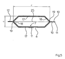
- the width c of the filling tube 7 is slightly more than twice as large as its depth d.
- the filling tube 7 has two pipe walls 17 aligned parallel to one another and parallel to the width c, which are connected to one another via outwardly directed film deflectors 18.
- the film deflectors 18 each have a rounded tip 19. But you could also describe the shape of a circular arc ( Figure 3) or a non-rounded tip 19 ( Figure 4).
- a transverse sealing device 13 with mutually movable transverse sealing jaws 14 is provided for welding the flattened film tube 6 transversely to its transport direction 15 to produce transverse seams 25.
- a separator 16 serves to separate a generated bag 8 from the film tube 6.
Landscapes
- Engineering & Computer Science (AREA)
- Mechanical Engineering (AREA)
- Containers And Plastic Fillers For Packaging (AREA)
Description
- Die Erfindung betrifft eine vertikale Schlauchbeutelmaschine gemäß dem Oberbegriff des Anspruchs 1. Eine solche Maschine ist aus der JP-A-3-85208 bekannt.
- Vertikale Schlauchbeutelmaschinen an sich sind hinlänglich bekannt. Derartige Verpackungsmaschinen dienen dazu, Schlauchbeutel aus einer von einer Vorratsrolle abgewickelten Folienbahn zu erzeugen. Die ebene Folienbahn wird dazu an einer Umlenkkante einer Formschulter zu einem Folienschlauch umgeformt. Die Umlenkkante erstreckt sich in vertikaler und in horizontaler Richtung. Zu ihrer Beschreibung ist also eine Angabe von Raumkoordinaten notwendig. In jedem Fall weist sie aber innerhalb einer Horizontalebene, auf welche die Raumkoordinaten projeziert werden können, nur Koordinatenpunkte auf, welche jeweils durch zwei Abstandswerte bestimmt sind, nämlich einen Breitenwert und einen Tiefenwert. Die zu einem Folienschlauch umgeformte Folienbahn wird sodann mittels eines Füllrohres, welches einen kreisförmigen Querschnitt aufweist, befüllt und verschweißt, um einen befüllten, relativ dicken Schlauchbeutel zu erzeugen. Dieser wird schließlich vom Folienschlauch mittels einer Trenneinrichtung abgetrennt. Das Füllrohr ist vertikal.ausgerichtet.
- Das bekannte, zylinderförmige Füllrohr erzeugt zunächst einen zylinderförmigen Folienschlauch, welcher nachfolgend insofern abgeflacht wird, als er von einer Quersiegeleinrichtung quer zu seiner Transportrichtung zusammengedrückt und derart verschweißt wird.
- Das bekannte, zylinderförmige Füllrohr hat den Nachteil, dass es für eine Erzeugung von sehr flachen Beuteln nicht geeignet ist. Zum anderen ist es auch nicht üblich, diese Flachbeutel mittels vertikaler Schlauchbeutelmaschinen herzustellen. In der Regel werden sogenannte Horizontalmaschinen zum Erzeugen von Flachbeuteln verwendet. Diese Maschinen haben dabei den Nachteil, dass die flachen, nicht standfähigen Beutel mittels Klammem oder Greifem gehandhabt werden, was relativ umständlich und daher leistungsmindernd ist. Zudem muss die Folienbahn angehalten werden, wenn eine Produktabgabe erfolgt, was ebenfalls die Verpackungsgeschwindigkeit beschränkt. Zwar gibt es mitlaufende Befüllstationen, diese verteuem eine Verpackungsanlage jedoch deutlich, so dass ihr Einsatz nur fallweise vorkommt.
- Der Erfindung liegt die Aufgabe zu Grunde, eine vertikale Schlauchbeutelmaschine der eingangs beschriebenen Art dahingehend weiterzuentwickeln, dass sie für eine Herstellung von Flachbeuteln, also Beutel mit vergleichsweise geringer Dicke, geeignet ist.
- Gelöst ist die Aufgabe gemäß dem kennzeichnenden Teil des Anspruchs 1.
- Das Füllrohr hat den Vorteil, dass es zum Fertigen von Flachbeuteln geeignet ist. Die relativ große Breite des Füllrohres führt zu relativ breiten Beuteln. Die relativ kleine Tiefe des Füllrohres bewirkt, dass der Folienschlauch eine vergleichsweise geringe Tiefe aufweist, welche eine geringe Beuteldicke vorgibt. Die Begriffe "Breite" und "Tiefe" sind so zu verstehen, dass sie einen direkten Bezug auf die Beutelform haben. Das Füllrohr erzeugt einen flachen Folienschlauch, welcher an die zu erzielenden Flachbeutel angepasst ist. Der Folienschlauch muss dabei der gewünschten Beutelform nicht exakt entsprechen. Es genügt, wenn der Folienschlauch genügend abgeflacht ist, um anschließend nur eine geringe weitergehende Deformation des Folienschlauches hin zum Schlauchbeutel zu erreichen. Das abgeflachte Füllrohr führt insgesamt dazu, dass die Folienbahn leichtgängiger, faltenfreier und ortsgenauer zu einer Flachbeutelform geführt wird. Dabei wird ein auf der Folienbahn vorhandenes Druckbild ortsgenau auf die Vorderseite und die Rückseite des Flachbeutels gebracht.
- Die erfindungsgemäße vertikale Schtauchbeutetmaschine hat weiterhin den Vorteil, dass Flachbeutel mit sehr hoher Maschinenleistung produziert werden können. Die bisher übliche Methode der Flachbeutelherstellung mittels horizontaler Verpackungsmaschinen, bei welcher in leistungsmindernder getakteter Arbeitsweise eine Handhabung der zu erzeugenden und zu befüllenden Flachbeutel erfolgt, kann somit durch eine schnellere kontinuierliche Verpackungsmethode der vertikalen Schlauchbeutelmaschine ersetzt werden.
- Weitere, vorteilhaften Ausgestaltungen der Erfindung sind in den Ansprüchen 2 bis 6 beschrieben.
- Eine deutliche Abflachung des Folienschlauches ist erreicht, wenn die Breite des Füllrohres mindestens anderthalb mal so groß wie deren Tiefe ist. In der Praxis erweist sich eine doppelt so große Breite wie Tiefe als günstig, sowohl bezüglich der Beutelform als auch bezüglich eines leichtgängigen Folienlaufs.
- Der abgeflachte Folienschlauch wird formstabil der Beutelerzeugung zugeführt, wenn eine Schlauchbeutelmaschinen ein Füllrohr aufweist, dessen Breite größer als dessen Tiefe ist, insbesondere mindestens anderthalb mal so groß.
- Die Schlauchbeutelmaschine ist dann optimal auf die Form der zu erreichenden Flachbeutel abgestimmt, wenn das Breite/Tiefe-Verhältnis der Umlenkkante dem Breite/Tiefe-Verhältnis des Füllrohres entspricht, insbesondere wenn es ebenso größer als 1, vorzugsweise mindestens 1,5 beträgt. Dies gilt auch für die Form eines Füllrohres, das zwei parallel zueinander und parallel zur Breite des Füllrohres ausgerichtete Rohrwände aufweist. Weist nämlich die Umlenkkante ein gekrümmtes Mittelstück auf, an welches sich beidseits ein gerades Schenkelstück anschließt, so wird eine besonders gute Beutelform erreicht. Die Schenkelstücke führen die Folienbahn in eine Schlauchform, welche zwei parallel zueinander ausgerichtete Schlauchwände aufweist. Diese Schlauchwände machen die beiden großen Seitenwände der Flachbeutel aus. Ein weiterer Vorteil dieser Form der Umlenkkante besteht darin, dass sie relativ einfach hergestellt werden kann, da diese geraden Bauteile in einfacher Weise schnell und präzise gefertigt werden können. Dies gilt auch für das gekrümmte Mittelstück, wenn dieses die Form eines Halbkreises oder einer Halbellipse aufweist.
- An den beiden Schmalseiten des Füllrohres ist jeweils ein Folienauslenker zum Auslenken des Folienschlauches vorgesehen, der sich vorzugsweise über die gesamte Länge des Füllrohres erstreckt. So werden die seitlichen Ränder des abgeflachten Füllrohres ausgelenkt und ortsgenau der Quersiegeleinrichtung zugeführt. Dabei sind mehrere geometrische Formen für die Ausgestaltung der Folienauslenker geeignet, wie z. B. eine Kreisbogenform, eine spitze Formgebung, sowie die Form einer abgerundeten Spitze. Diese Formen sind für den Querschnitt des Füllrohres in Richtung quer zu seiner Mittelachse vorgesehen.
- Auf gegenüberliegenden Seiten des Füllrohres ist jeweils eine Längssiegeleinrichtung zum Verschweißen eines Schlauchrandes vorgesehen. So können derart gegenüberliegende Ränder des abgeflachten Folienschlauches, oder der erzeugten Flachbeutel verschweißt werden, um eine flache, nach einer Beutelbefüllung noch weniger ausbauchende Beutelform zu erreichen.
- Im folgenden wird die Erfindung an Hand von Ausführungsbeispiele darstellenden Figuren näher beschrieben. Es zeigt:
- Figur 1
- in einer Seitenansicht eine vertikale Schlauchbeutelmaschine mit einer von einer Vorratsrolle abgewickelten Folienbahn, welche mittels eines Folienabzuges weitertransportiert wird, wobei an einer Umlenkkante einer Formschulter die Folienbahn zu einem abgeflachten Folienschlauch umgeformt wird, welcher ein abgeflachtes Füllrohr umgibt, mit einer Längssiegeleinrichtung und einer Quersiegeleinrichtung zum Verschweißen des Folienschlauches, und mit einer Trenneinrichtung in einer Quersiegelbacke zum Abtrennen eines befüllten und verschweißten Flachbeutels vom Folienschlauch;
- Figur 2
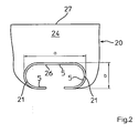
- in einer Ansicht von oben die Formschulter gemäß Figur 1, wobei die Umlenkkante der Formschulter eine größere Breite a als Tiefe b aufweist;
- Figur 3
- in einem Querschnitt eine Ausgestaltung eines abgeflachten Füllrohres, sowie
- Figur 4
- in einem Querschnitt eine weitere Ausgestaltung eines abgeflachten Füllrohres.
- Figur 5
- in einer Schnittdarstellung das entlang A-A der Figur 1 geschnittene, abgeflachte Füllrohr der Figur 1, mitsamt dem Folienschlauch, welcher entlang seiner gegenüberliegenden Ränder verschweißt ist;
- Bei einer vertikalen Schlauchbeutelmaschine 1 (Figur 1) wird eine Folienbahn 2 mittels eines Abzugs 3 von einer Vorratsrolle 4 abgewickelt und mittels einer Umlenkkante 5 (Figur 2) zu einem Folienschlauch 6 umgeformt. Der Folienschlauch 6 umschließt ein Füllrohr 7 welches abgeflacht ist (Figur 3, 4), um flache Beutel 8 herzustellen.
- Zwei Längssiegeleinrichtungen 9 auf gegenüberliegenden Seiten des Füllrohres 7 sind zum Längsverschweißen des Folienschlauches 6 vorgesehen, wobei eine Längssiegeleinrichtung 9 die Ränder 10 der Folienbahn 2 miteinander verschweißt, um eine randseitige Längsnaht 11 des flachen Beutels 8 zu erzeugen. Mit den anderen Längssiegeleinrichtungen 9 werden parallel zur Längsnaht 11 verlaufende, weitere randseitige Längsnähte 11, 12 im dort entsprechend ausgelenkten Folienschlauch 6 erreicht. Die Beutelform ist infolge des abgeflachten Füllrohres 6 und der beiden randseitigen Längsnähte 11, 12 relativ flach (Flachbeutel). Die Breite c des Füllrohres 7 ist etwas mehr als doppelt so groß wie dessen Tiefe d. Das Füllrohr 7 weist zwei parallel zueinander und parallel zur Breite c ausgerichtete Rohrwände 17 auf, welche über nach außen gerichtete Folienauslenker 18 miteinander verbunden sind. Die Folienauslenker 18 weisen jeweils eine abgerundete Spitze 19 auf. Sie könnten aber auch die Form eines Kreisbogens (Figur 3) oder eine nicht abgerundete Spitze 19 (Figur 4) beschreiben.
- Eine Quersiegeleinrichtung 13 mit gegeneinander bewegbaren Quersiegelbacken 14 ist zum Verschweißen des abgeflachten Folienschlauches 6 quer zu seiner Transportrichtung 15 unter Erzeugung von Quernähten 25 vorgesehen. Eine Trenneinrichtung 16 dient zum Abtrennen eines erzeugten Beutels 8 vom Folienschlauch 6.
- Die Vorrichtung 20 zum Umformen der Folienbahn 2 ist analog Figur 2 ausgebildet.
- a
- Breite der Umlenkkante 5
- b
- Tiefe der Umlenkkante 5
- c
- Breite des Füllrohres 7
- d
- Tiefe des Füllrohres 7
- 1
- vertikale Schlauchbeutelmaschine
- 2
- Folienbahn
- 3
- Abzug
- 4
- Vorratsrolle
- 5
- Umlenkkante
- 6
- Folienschlauch
- 7
- Füllrohr
- 8
- Beutel
- 9
- Längssiegeleinrichtung
- 10
- Rand
- 11
- Längsnaht
- 13
- Quersiegeleinrichtung
- 14
- Quersiegelbacke
- 15
- Transportrichtung
- 16
- Trenneinrichtung
- 17
- Rohrwand
- 18
- Folienauslenker
- 19
- Spitze
- 20
- Vorrichtung
- 21
- Krümmung
- 24
- tragende Fläche
- 25
- Quernaht
- 26
- Mittelstück
- 27
- Folienlaufkante
Claims (6)
- Vertikale Schlauchbeutelmaschine (1) mit einem Füllrohr (7), dessen Breite (c) größer als dessen Tiefe (d) ist, wobei eine Folienbahn (2) mittels eines Abzugs (3) von einer Vorratsrolle (4) abgewickelt und mittels einer Umlenkkante (5) einer an das Füllrohr (7) angepassten Vorrichtung (20) zum Umformen der Folienbahn (2) zu einem Folienschlauch (6) umgeformt wird, wobei der Folienschlauch (6) über eine Folieneinlaufkante (27) der Vorrichtung (20) in diese einläuft und durch Passieren der Vorrichtung (20) das Füllrohr (7) umschließt, eine Längssiegeleinrichtung (9) zum Verschweißen der Ränder (10) der Folienbahn (2) und damit zum Längsverschweißen des Folienschlauches (6) vorgesehen ist, eine Quersiegeleinrichtung (13) mit gegeneinander bewegbaren Quersiegelbacken (14) zum Verschweißen des Folienschlauches (6) quer zu seiner Transportrichtung (15) vorgesehen ist, mit einer Trenneinrichtung (16) zum Abtrennen eines erzeugten Beutels (8) vom Folienschlauch (6), wobei die Umlenkkante (5) ein Mittelstück (26) aufweist, welches sich in eine parallel zur Ausrichtung der Folieneinlaufkante (27) ausgerichtete Breite (a) erstreckt, wobei sich an das Mittelstück (26) an gegenüberliegenden Seiten jeweils eine Krümmung (21) anschließt, die maximale Entfernung der Krümmungen (21) die Breite (a) beschreibt, die Breite (a) der Umlenkkante (5) größer als deren Tiefe (b) ist, und das Füllrohr (7) an seinen beiden Schmalseiten jeweils einen Folienauslenker (18) zum Auslenken des Folienschlauches (6) aufweist, der sich vorzugsweise über die gesamte Länge des Füllrohres (7) erstreckt, dadurch gekennzeichnet, dass auf zwei gegenüberliegenden Seiten des Füllrohres (7), an denen die Folienauslenker (18) vorgesehen sind, jeweils eine vom Folienauslenker (18) weg weisende Längsnaht (11, 12) im Folienschlauch (6) ausgebildet ist, zu deren Erzeugung jeweils eine Längssiegeleinrichtung (9) zum Verschweißen der Seitenränder der Beutel (8) vorgesehen ist, und dass die die Ränder (10) der Folienbahn (2) verschweißende Längssiegeleinrichtung (9) auf der der Folieneinlaufkante (27) gegenüber liegenden Seite des Füllrohres (7) angeordnet ist.
- Schlauchbeutelmaschine nach Anspruch 1, dadurch gekennzeichnet, dass die Breite (c) des Füllrohres (7) mindestens anderthalb mal so groß wie dessen Tiefe (d) ist.
- Schlauchbeutelmaschine nach Anspruch 1 oder Anspruch 2, dadurch gekennzeichnet, dass das Füllrohr (7) zwei parallel zueinander und parallel zur Breite (c) des Füllrohres (7) ausgerichtete Rohrwände (17) aufweist.
- Schlauchbeutelmaschine nach Anspruch 1, dadurch gekennzeichnet, dass der Folienauslenker (18) im Querschnitt kreisbogenförmig ausgestaltet ist.
- Schlauchbeutelmaschine nach Anspruch 1, dadurch gekennzeichnet, dass der Folienauslenker (18) im Querschnitt eine Spitze (19) aufweist, welche vorzugsweise mittig am Folienauslenker (18) vorgesehen ist.
- Schlauchbeutelmaschine nach Anspruch 5, dadurch gekennzeichnet, dass die Spitze (19) abgerundet ist.
Applications Claiming Priority (2)
| Application Number | Priority Date | Filing Date | Title |
|---|---|---|---|
| DE10251068A DE10251068A1 (de) | 2002-11-02 | 2002-11-02 | Füllrohr, sowie vertikale Schlauchbeutelmaschine mit einem derartigen Füllrohr |
| DE10251068 | 2002-11-02 |
Publications (2)
| Publication Number | Publication Date |
|---|---|
| EP1415910A1 EP1415910A1 (de) | 2004-05-06 |
| EP1415910B1 true EP1415910B1 (de) | 2007-03-14 |
Family
ID=32087324
Family Applications (1)
| Application Number | Title | Priority Date | Filing Date |
|---|---|---|---|
| EP03019728A Expired - Lifetime EP1415910B1 (de) | 2002-11-02 | 2003-08-29 | Vertikale Schlauchbeutelmaschine |
Country Status (3)
| Country | Link |
|---|---|
| EP (1) | EP1415910B1 (de) |
| DE (2) | DE10251068A1 (de) |
| ES (1) | ES2285017T3 (de) |
Family Cites Families (11)
| Publication number | Priority date | Publication date | Assignee | Title |
|---|---|---|---|---|
| DE7421274U (de) * | 1974-10-03 | Iveco Israel Weissbort | Beutelform- und Wareneinfüllschulter für Halbschlauchfolien | |
| US2160367A (en) * | 1937-11-27 | 1939-05-30 | Stokes & Smith Co | Method of making sealed packages |
| GB528833A (en) * | 1938-05-25 | 1940-11-07 | Pad Y Wax Company Inc | Packaging methods and machines |
| DE1152937B (de) * | 1960-02-01 | 1963-08-14 | William C Leasure | Verfahren zum Herstellen von Verpackungen aus einem zum Schlauch geformten Verpackungsmaterial und Vorrichtung zur Durchfuehrung des Verfahrens |
| US3133390A (en) * | 1961-09-26 | 1964-05-19 | William C Leasure | Apparatus for sealing strip material |
| US3538676A (en) * | 1967-03-08 | 1970-11-10 | William R Runo | Packaging machine |
| DE2323599C2 (de) * | 1973-05-10 | 1983-08-11 | Wennemar 6200 Wiesbaden Bree | Vorrichtung zum Verpacken schütt-oder fließfähiger Güter |
| DE2657790A1 (de) * | 1976-12-21 | 1978-06-22 | Rovema Gmbh | Schlauchbeutelmaschine |
| DE2721550A1 (de) * | 1977-05-13 | 1978-11-16 | Abg Gmbh | Beutelpackmaschine |
| US5400565A (en) * | 1992-06-29 | 1995-03-28 | Pacmac, Inc. | Vertical form, fill and seal packaging machine for making recloseable product filled bags |
| US6182426B1 (en) * | 1998-10-19 | 2001-02-06 | Liqui-Box Corporation | Vertical form, fill, seal machine and methods |
-
2002
- 2002-11-02 DE DE10251068A patent/DE10251068A1/de not_active Withdrawn
-
2003
- 2003-08-29 DE DE50306794T patent/DE50306794D1/de not_active Expired - Fee Related
- 2003-08-29 EP EP03019728A patent/EP1415910B1/de not_active Expired - Lifetime
- 2003-08-29 ES ES03019728T patent/ES2285017T3/es not_active Expired - Lifetime
Also Published As
| Publication number | Publication date |
|---|---|
| ES2285017T3 (es) | 2007-11-16 |
| EP1415910A1 (de) | 2004-05-06 |
| DE50306794D1 (de) | 2007-04-26 |
| DE10251068A1 (de) | 2004-05-13 |
Similar Documents
| Publication | Publication Date | Title |
|---|---|---|
| DE19858567C2 (de) | Vorrichtung zum Herstellen von Schlauchbeutelpackungen | |
| DE10017479A1 (de) | Vertikale Schlauchbeutelmaschine und damit erzeugter Beutel | |
| EP1456084B1 (de) | Verfahren und vorrichtung zum herstellen von beutelpackungen | |
| EP0627355B1 (de) | Vorrichtung zur Herstellung von Schlauchbeuteln | |
| CH627413A5 (de) | Schlauchbeutelmaschine. | |
| DE19957891A1 (de) | Schlauchbeutelmaschine | |
| DE8401629U1 (de) | Vorrichtung zum Heißgasschweißen | |
| EP2632695B1 (de) | Siegelbacke zur siegelung eines packstoffs mittels ultraschall | |
| EP1597059A1 (de) | Verfahren zur herstellung von säcken | |
| EP0797526B1 (de) | Schlauchbeutelmaschine | |
| EP2480458A1 (de) | Formschulter und vorrichtung zum herstellen von schlauchbeuteln | |
| DE19539832B4 (de) | Verfahren und Vorrichtung zur Herstellung von Beuteln mit mindestens einem entlang einer Linie ausgedehnten Versteifungsbereich | |
| EP1415912A1 (de) | Formschulter zum Umformen einer Folienbahn | |
| DE102011075378A1 (de) | Schlauchbeutelmaschine | |
| DE102010002653A1 (de) | Vorrichtung zur Herstellung von Beutelpackungen | |
| DE102004038006A1 (de) | Vorrichtung und Verfahren zur Herstellung und Befüllung von Säcken | |
| EP1356917A2 (de) | Vorrichtung zum Ausbilden und/oder Verschliessen einer Verpackungseinheit | |
| EP1415910A1 (de) | Füllrohr, sowie vertikale Schlauchbeutelmaschine mit einem derartigen Füllrohr | |
| DE10251070A1 (de) | Vorrichtung zum Umformen einer Folienbahn und vertikale Schlauchbeutelmaschine mit einer derartigen Vorrichtung | |
| EP1415911B1 (de) | Umlenkkante zum Umformen einer Folienbahn und vertikale Schlauchbeutelmaschine mit einer derartigen Umlenkkante | |
| DE10027581A1 (de) | Schlauchbeutelmaschine zur Herstellung von Beuteln mit Kantensiegelung | |
| AT394696B (de) | Vorrichtung zum fuellen von offenen saecken | |
| DE2203466A1 (de) | Verfahren und Vorrichtung zur Herstellung eines Schlauches aus weichem,verschweissbarem Material | |
| DE19924626A1 (de) | Verfahren zum Herstellen von mit Traggriffen, vorzugsweise Schlaufengriffen versehenen Tragetaschen aus einer thermoplastischen Kunststoffolienbahn | |
| DE10304913A1 (de) | Vorrichtung zum Aufnehmen eines Folienschlauches und vertikale Schlauchbeutelmaschine mit einer derartigen Vorrichtung |
Legal Events
| Date | Code | Title | Description |
|---|---|---|---|
| PUAI | Public reference made under article 153(3) epc to a published international application that has entered the european phase |
Free format text: ORIGINAL CODE: 0009012 |
|
| 17P | Request for examination filed |
Effective date: 20030926 |
|
| AK | Designated contracting states |
Kind code of ref document: A1 Designated state(s): AT BE BG CH CY CZ DE DK EE ES FI FR GB GR HU IE IT LI LU MC NL PT RO SE SI SK TR |
|
| AX | Request for extension of the european patent |
Extension state: AL LT LV MK |
|
| AKX | Designation fees paid |
Designated state(s): DE ES FR GB IT NL |
|
| 17Q | First examination report despatched |
Effective date: 20041215 |
|
| RTI1 | Title (correction) |
Free format text: VERTICAL BAG FORMING, FILLING AND SEALING MACHINE |
|
| GRAP | Despatch of communication of intention to grant a patent |
Free format text: ORIGINAL CODE: EPIDOSNIGR1 |
|
| GRAS | Grant fee paid |
Free format text: ORIGINAL CODE: EPIDOSNIGR3 |
|
| GRAA | (expected) grant |
Free format text: ORIGINAL CODE: 0009210 |
|
| AK | Designated contracting states |
Kind code of ref document: B1 Designated state(s): DE ES FR GB IT NL |
|
| REG | Reference to a national code |
Ref country code: GB Ref legal event code: FG4D Free format text: NOT ENGLISH |
|
| REF | Corresponds to: |
Ref document number: 50306794 Country of ref document: DE Date of ref document: 20070426 Kind code of ref document: P |
|
| GBT | Gb: translation of ep patent filed (gb section 77(6)(a)/1977) |
Effective date: 20070606 |
|
| ET | Fr: translation filed | ||
| REG | Reference to a national code |
Ref country code: ES Ref legal event code: FG2A Ref document number: 2285017 Country of ref document: ES Kind code of ref document: T3 |
|
| PLBE | No opposition filed within time limit |
Free format text: ORIGINAL CODE: 0009261 |
|
| STAA | Information on the status of an ep patent application or granted ep patent |
Free format text: STATUS: NO OPPOSITION FILED WITHIN TIME LIMIT |
|
| 26N | No opposition filed |
Effective date: 20071217 |
|
| PG25 | Lapsed in a contracting state [announced via postgrant information from national office to epo] |
Ref country code: IT Free format text: LAPSE BECAUSE OF NON-PAYMENT OF DUE FEES Effective date: 20070829 |
|
| PGFP | Annual fee paid to national office [announced via postgrant information from national office to epo] |
Ref country code: ES Payment date: 20080828 Year of fee payment: 6 Ref country code: NL Payment date: 20080813 Year of fee payment: 6 |
|
| PGFP | Annual fee paid to national office [announced via postgrant information from national office to epo] |
Ref country code: FR Payment date: 20080813 Year of fee payment: 6 |
|
| PGFP | Annual fee paid to national office [announced via postgrant information from national office to epo] |
Ref country code: GB Payment date: 20080821 Year of fee payment: 6 |
|
| PGFP | Annual fee paid to national office [announced via postgrant information from national office to epo] |
Ref country code: DE Payment date: 20081023 Year of fee payment: 6 |
|
| REG | Reference to a national code |
Ref country code: NL Ref legal event code: V1 Effective date: 20100301 |
|
| GBPC | Gb: european patent ceased through non-payment of renewal fee |
Effective date: 20090829 |
|
| REG | Reference to a national code |
Ref country code: FR Ref legal event code: ST Effective date: 20100430 |
|
| PG25 | Lapsed in a contracting state [announced via postgrant information from national office to epo] |
Ref country code: DE Free format text: LAPSE BECAUSE OF NON-PAYMENT OF DUE FEES Effective date: 20100302 Ref country code: FR Free format text: LAPSE BECAUSE OF NON-PAYMENT OF DUE FEES Effective date: 20090831 Ref country code: NL Free format text: LAPSE BECAUSE OF NON-PAYMENT OF DUE FEES Effective date: 20100301 |
|
| REG | Reference to a national code |
Ref country code: ES Ref legal event code: FD2A Effective date: 20090831 |
|
| PG25 | Lapsed in a contracting state [announced via postgrant information from national office to epo] |
Ref country code: GB Free format text: LAPSE BECAUSE OF NON-PAYMENT OF DUE FEES Effective date: 20090829 |
|
| PG25 | Lapsed in a contracting state [announced via postgrant information from national office to epo] |
Ref country code: ES Free format text: LAPSE BECAUSE OF NON-PAYMENT OF DUE FEES Effective date: 20090830 |