EP1415843A2 - Tankeinfüllstutzen - Google Patents
Tankeinfüllstutzen Download PDFInfo
- Publication number
- EP1415843A2 EP1415843A2 EP03022357A EP03022357A EP1415843A2 EP 1415843 A2 EP1415843 A2 EP 1415843A2 EP 03022357 A EP03022357 A EP 03022357A EP 03022357 A EP03022357 A EP 03022357A EP 1415843 A2 EP1415843 A2 EP 1415843A2
- Authority
- EP
- European Patent Office
- Prior art keywords
- sleeve
- filler neck
- tank filler
- opening
- ring
- Prior art date
- Legal status (The legal status is an assumption and is not a legal conclusion. Google has not performed a legal analysis and makes no representation as to the accuracy of the status listed.)
- Withdrawn
Links
Images


Classifications
-
- B—PERFORMING OPERATIONS; TRANSPORTING
- B60—VEHICLES IN GENERAL
- B60K—ARRANGEMENT OR MOUNTING OF PROPULSION UNITS OR OF TRANSMISSIONS IN VEHICLES; ARRANGEMENT OR MOUNTING OF PLURAL DIVERSE PRIME-MOVERS IN VEHICLES; AUXILIARY DRIVES FOR VEHICLES; INSTRUMENTATION OR DASHBOARDS FOR VEHICLES; ARRANGEMENTS IN CONNECTION WITH COOLING, AIR INTAKE, GAS EXHAUST OR FUEL SUPPLY OF PROPULSION UNITS IN VEHICLES
- B60K15/00—Arrangement in connection with fuel supply of combustion engines or other fuel consuming energy converters, e.g. fuel cells; Mounting or construction of fuel tanks
- B60K15/03—Fuel tanks
- B60K15/04—Tank inlets
-
- B—PERFORMING OPERATIONS; TRANSPORTING
- B60—VEHICLES IN GENERAL
- B60K—ARRANGEMENT OR MOUNTING OF PROPULSION UNITS OR OF TRANSMISSIONS IN VEHICLES; ARRANGEMENT OR MOUNTING OF PLURAL DIVERSE PRIME-MOVERS IN VEHICLES; AUXILIARY DRIVES FOR VEHICLES; INSTRUMENTATION OR DASHBOARDS FOR VEHICLES; ARRANGEMENTS IN CONNECTION WITH COOLING, AIR INTAKE, GAS EXHAUST OR FUEL SUPPLY OF PROPULSION UNITS IN VEHICLES
- B60K15/00—Arrangement in connection with fuel supply of combustion engines or other fuel consuming energy converters, e.g. fuel cells; Mounting or construction of fuel tanks
- B60K15/03—Fuel tanks
- B60K2015/03328—Arrangements or special measures related to fuel tanks or fuel handling
- B60K2015/03361—Arrangements or special measures related to fuel tanks or fuel handling for checking the quality or quantity of fuel during filling of fuel tank
Definitions
- the invention is the provision as a technical problem based on a tank filler neck, with comparatively low cost and feasible for all fuels can be used.
- the invention solves this problem by providing a tank filler neck with the features of claim 1.
- This tank filler neck is the tank filler neck enclosing annular sleeve provided on the neck is pluggable.
- a refinished according to claim 2 tank filler neck shows that the sleeve has a sleeve ring and arranged perpendicular thereto having a collar.
- the sleeve ring is in the further referred to as a ring.
- the sleeve has a Make an aperture and radially opposite hinge-like element, so that the collar respectively opposite essentially between hinge-like Element and aperture is located.
- the hinge-like element can have different shapes. It can, for example be less than or equal to the size of the sleeve ring, it may be reduced in thickness or contain a notch.
- the sleeve must be in the area of its hinge-like element the required angle can be widened. Must have the sleeve or the sleeve ring at this point a corresponding Have flexibility. This fact is by means of Shaping, locking elements and used material bill carried.
- the sleeve is preferably made of plastic.
- this sleeve which with a Visual indication of the fuel to be used, Can be retrofitted on all tank filler neck, regardless of whether this equipped with an additional Crashring is or not.
- Provided locking elements To the necessary hold of the sleeve on the respective To ensure filler neck, are so-called Provided locking elements.
- the particularly simple assembly and to call the cost-effective production of the sleeve advantageously also saves the expensive change or the availability of different Variants of tank filler neck and tank caps for Distinction of the fuel.
- Fig. 1 shows a section through a Tank filler neck 1 without cover.
- Socket 2 of the filler neck 1 has at its upper end in the direction of the lid (not shown) one Crashring 3 up.
- On the Crashring 3 a sleeve 4 is attached, a sleeve ring 4 ', a collar 8 and a locking element 5 contains.
- the locking element 5 provides an additional Hold, so that the sleeve 4 is not displaced in the axial direction is.
- Fig. 2 also shows a section through a tank filler neck 1 without cover.
- the clarity half are the same for functionally identical components Reference is made to the above Description of Fig. 1 referenced.
- the on the Crashring 3 plugged sleeve 4 shows a part of a locking element. 7 in the sleeve ring 4 '(not figured in Fig. 2 sleeve ring 4 'begins directly after the collar 8), wherein the locking element 7 for reasons of flexibility only at one Side with the sleeve ring 4 'in contact and on the other 3 pages has an interruption 9.
- the locking element 7 continues to serve for tolerance compensation in the radial direction of the ring, so it also with different tank filler neck and with temperature differences, a secure hold the sleeve 4 granted.
- Fig. 3 shows the top of a partially sectioned Filler neck 1 with a plugged onto the base 2 Sleeve 4.
- the sleeve 4 is suitable for latching Plug connection 10 in the closed state of the sleeve 4 and more on the sleeve ring 4 'arranged locking elements 5 and 7 with corresponding interruptions 9 dar.
- the at the top of the base 2 arranged Crashring shows a nose 11 for Leakage of spilled fuel.
- a hinge-like element 12 which for Assembly relief is used. To the bulge through the nose 11 to include accordingly, the hinge-like element 12 contain a notch.
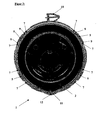
- Fig. 4 shows the top view of a base 2 of a tank filler neck 1 with attached sleeve 4.
- a nose 11 to spill the spilled Fuel.
- the hinged element 12 To the bulge through the nose 11 to include accordingly, the hinge-like element 12 contain a notch.
- Radially opposite the sleeve 4 has an interruption 13, at the respective Ends the corresponding connector elements (not shown) 10 are arranged.
- the on the preferred color colored sleeve 4 applied lettering with the to be used fuel is a mix-up in addition exclude.
- Fig. 5 shows the side view of a filler neck 1 with the plugged on the base 2 sleeve 4, the clarity half the same for functionally identical components Reference numerals are used and in this respect to the above Descriptions of Figs. 1 to 4 can be referenced.
- the locking element 7 shown in Fig. 2 and 3 shows in this Representation quite clearly provided in the sleeve ring 4 ' Interruptions 9 on. Also, the respective, after the Key / lock principle functioning elements of the connector 10 are shown here again visible.
Landscapes
- Engineering & Computer Science (AREA)
- Life Sciences & Earth Sciences (AREA)
- Sustainable Development (AREA)
- Sustainable Energy (AREA)
- Chemical & Material Sciences (AREA)
- Combustion & Propulsion (AREA)
- Transportation (AREA)
- Mechanical Engineering (AREA)
- Closures For Containers (AREA)
- Cooling, Air Intake And Gas Exhaust, And Fuel Tank Arrangements In Propulsion Units (AREA)
Abstract
Description
- Fig. 1
- einen Tankeinfüllstutzen mit Crashring und Hülse, wobei die Hülse ein Rastelement A aufweist
- Fig. 2
- einen Tankeinfüllstutzen mit Hülse, wobei die Hülse ein Rastelement B zeigt
- Fig. 3
- die Oberseite der Hülse mit Verrastung und Steckverbindung
- Fig. 4
- die Hülse im eingebauten Zustand auf dem Tankeinfüllstutzen
- Fig. 5
- eine Seitenansicht der Hülse
Claims (4)
- Tankeinfüllstutzen (1) mit einer Öffnung zum Einführen einer Zapfpistole und einem Deckel zum Verschließen dieser Öffnung,
dadurch gekennzeichnet, dass eine den Tankeinfüllstutzen (1) umschließende ringförmige Hülse (4) vorgesehen ist, die auf den Stutzen (1) aufsteckbar ist. - Vorrichtung nach Anspruch 1,
dadurch gekennzeichnet, dass die Hülse (4) einen Ring (4') und senkrecht dazu angeordnet einen Kragen (8) aufweist, wobei die Hülse (4) an einer Stelle eine Durchbrechung (13) und radial gegenüberliegend ein scharnierartiges Element (12) aufweist, so daß sich der Kragen (8) jeweils gegenüberliegend im wesentlichen zwischen scharnierartigen Element (12) und Durchbrechung (13) befindet. - Vorrichtung nach Anspruch 2,
dadurch gekennzeichnet, dass die Durchbrechung (13) der Hülse (4) durch ein an Kragen (8) und Ring (4') beidseitig der Durchbrechung (13) angeordnete Steckverbindung (10) verschließbar ist. - Vorrichtung nach Anspruch 1,
dadurch gekennzeichnet, dass das scharnierartige Element (12) eine Einkerbung aufweist, die mit einer Nase (11) am Einfüllstutzen (1) zusammenwirkt.
Applications Claiming Priority (2)
| Application Number | Priority Date | Filing Date | Title |
|---|---|---|---|
| DE20216928U | 2002-10-31 | ||
| DE20216928U DE20216928U1 (de) | 2002-10-31 | 2002-10-31 | Tankeinfüllstutzen |
Publications (2)
| Publication Number | Publication Date |
|---|---|
| EP1415843A2 true EP1415843A2 (de) | 2004-05-06 |
| EP1415843A3 EP1415843A3 (de) | 2004-10-27 |
Family
ID=7976577
Family Applications (1)
| Application Number | Title | Priority Date | Filing Date |
|---|---|---|---|
| EP03022357A Withdrawn EP1415843A3 (de) | 2002-10-31 | 2003-10-04 | Tankeinfüllstutzen |
Country Status (2)
| Country | Link |
|---|---|
| EP (1) | EP1415843A3 (de) |
| DE (1) | DE20216928U1 (de) |
Family Cites Families (5)
| Publication number | Priority date | Publication date | Assignee | Title |
|---|---|---|---|---|
| DE3027002A1 (de) | 1980-07-17 | 1982-02-11 | Volkswagenwerk Ag, 3180 Wolfsburg | Tankeinfuellstutzen-anordnung, insbesondere fuer kraftfahrzeuge |
| DE8131743U1 (de) | 1981-10-30 | 1983-03-24 | Elbatainer Kunststoff- Und Verpackungsgesellschaft Mbh, 7505 Ettlingen | Verbindung rohrfoermiger Kunststoff- und Metallteile |
| DE3530964C1 (en) | 1985-08-30 | 1987-03-05 | Schulte H J S Gmbh & Co | Closure for a petrol filler neck of a motor vehicle |
| DE4002750A1 (de) * | 1990-01-31 | 1990-05-31 | Wolfgang Richard Mastnak | Kontrollringe zur tankinhaltsbestimmung |
| DE19709416C1 (de) | 1997-03-07 | 1998-04-30 | Daimler Benz Ag | Vorrichtung zum roboterfähigen Betanken eines Fahrzeuges |
-
2002
- 2002-10-31 DE DE20216928U patent/DE20216928U1/de not_active Expired - Lifetime
-
2003
- 2003-10-04 EP EP03022357A patent/EP1415843A3/de not_active Withdrawn
Also Published As
| Publication number | Publication date |
|---|---|
| DE20216928U1 (de) | 2003-01-02 |
| EP1415843A3 (de) | 2004-10-27 |
Similar Documents
| Publication | Publication Date | Title |
|---|---|---|
| DE10037824B4 (de) | Vorrichtung zum Verhindern des Einführens einer Zapfpistole | |
| DE102010002448B4 (de) | Kraftstoffbehälteröffnungsschließvorrichtung | |
| DE69006557T2 (de) | Absteckteil für einen Brennstoffbehälter. | |
| DE102013114804B4 (de) | Vorrichtung zum Verhindern einer Fehlbetankung eines Fahrzeugs | |
| DE2500852C2 (de) | Verschlußkappe für den Füllstutzen eines Tanks | |
| DE3005419C2 (de) | Renkverschlußdeckel für einen Tank | |
| DE102004035098A1 (de) | Inwändiges Bauteil für Kraftstofftanks | |
| DE2407130A1 (de) | Kraftstoffbehaelter, insbesondere von kraftfahrzeugen | |
| DE3834633A1 (de) | Kraftstoffbehaelterverschluss | |
| DE2553254A1 (de) | Kuehler insbesondere fuer kraftfahrzeuge | |
| DE112017006607T5 (de) | Bidirektionaler no-filter-no-run-stift | |
| DE112017000414B4 (de) | Ein „Kein Filter, kein Betrieb“-Aufsatz, eine Fluidfilterbaugruppe und ein Verfahren zum Betrieb einer Fluidfilterbaugruppe | |
| DE102011078339A1 (de) | Kraftstofftanköffnungs- und Schließvorrichtung | |
| WO2007118613A1 (de) | Flüssigkeitsbehälter | |
| DE102020124298A1 (de) | Deckellose einfüllstutzenstruktur | |
| EP1264725B1 (de) | Verschluss für einen Tank eines Kraftfahrzeuges | |
| EP1415843A2 (de) | Tankeinfüllstutzen | |
| EP0307971B1 (de) | Kupplungsmuffe zum Verbinden von zwei Rohrleitungsenden | |
| DE202005004189U1 (de) | Tankstutzen | |
| DE102018210376A1 (de) | Tankkoppelstelle für ein Fahrzeug | |
| DE3903508C2 (de) | ||
| DE19800788C2 (de) | 2-Takt-Brennkraftmaschine | |
| EP0623771B1 (de) | Unterbrechungsventil | |
| DE102017127954B4 (de) | Doppelkappenanordnung mit mehreren Passagen | |
| DE202021101335U1 (de) | Schutzsystem für einen ersten Deckel eines Tanks für Abgasreinigungsadditiv in einem Kraftfahrzeug |
Legal Events
| Date | Code | Title | Description |
|---|---|---|---|
| PUAI | Public reference made under article 153(3) epc to a published international application that has entered the european phase |
Free format text: ORIGINAL CODE: 0009012 |
|
| AK | Designated contracting states |
Kind code of ref document: A2 Designated state(s): AT BE BG CH CY CZ DE DK EE ES FI FR GB GR HU IE IT LI LU MC NL PT RO SE SI SK TR |
|
| AX | Request for extension of the european patent |
Extension state: AL LT LV MK |
|
| PUAL | Search report despatched |
Free format text: ORIGINAL CODE: 0009013 |
|
| AK | Designated contracting states |
Kind code of ref document: A3 Designated state(s): AT BE BG CH CY CZ DE DK EE ES FI FR GB GR HU IE IT LI LU MC NL PT RO SE SI SK TR |
|
| AX | Request for extension of the european patent |
Extension state: AL LT LV MK |
|
| 17P | Request for examination filed |
Effective date: 20040924 |
|
| 17Q | First examination report despatched |
Effective date: 20050525 |
|
| AKX | Designation fees paid |
Designated state(s): AT BE BG CH CY CZ DE DK EE ES FI FR GB GR HU IE IT LI LU MC NL PT RO SE SI SK TR |
|
| STAA | Information on the status of an ep patent application or granted ep patent |
Free format text: STATUS: THE APPLICATION IS DEEMED TO BE WITHDRAWN |
|
| 18D | Application deemed to be withdrawn |
Effective date: 20051206 |