EP1415523A1 - Sämaschine - Google Patents
Sämaschine Download PDFInfo
- Publication number
- EP1415523A1 EP1415523A1 EP20030017336 EP03017336A EP1415523A1 EP 1415523 A1 EP1415523 A1 EP 1415523A1 EP 20030017336 EP20030017336 EP 20030017336 EP 03017336 A EP03017336 A EP 03017336A EP 1415523 A1 EP1415523 A1 EP 1415523A1
- Authority
- EP
- European Patent Office
- Prior art keywords
- sowing
- seed
- unit
- units
- seeder
- Prior art date
- Legal status (The legal status is an assumption and is not a legal conclusion. Google has not performed a legal analysis and makes no representation as to the accuracy of the status listed.)
- Granted
Links
Images


Classifications
-
- A—HUMAN NECESSITIES
- A01—AGRICULTURE; FORESTRY; ANIMAL HUSBANDRY; HUNTING; TRAPPING; FISHING
- A01B—SOIL WORKING IN AGRICULTURE OR FORESTRY; PARTS, DETAILS, OR ACCESSORIES OF AGRICULTURAL MACHINES OR IMPLEMENTS, IN GENERAL
- A01B79/00—Methods for working soil
- A01B79/005—Precision agriculture
-
- A—HUMAN NECESSITIES
- A01—AGRICULTURE; FORESTRY; ANIMAL HUSBANDRY; HUNTING; TRAPPING; FISHING
- A01C—PLANTING; SOWING; FERTILISING
- A01C21/00—Methods of fertilising, sowing or planting
- A01C21/005—Following a specific plan, e.g. pattern
-
- A—HUMAN NECESSITIES
- A01—AGRICULTURE; FORESTRY; ANIMAL HUSBANDRY; HUNTING; TRAPPING; FISHING
- A01C—PLANTING; SOWING; FERTILISING
- A01C7/00—Sowing
- A01C7/08—Broadcast seeders; Seeders depositing seeds in rows
- A01C7/10—Devices for adjusting the seed-box ; Regulation of machines for depositing quantities at intervals
- A01C7/102—Regulating or controlling the seed rate
Definitions
- the invention relates to a seed drill, in particular for a Single-grain sowing, as used, for example, for sowing maize, Sugar beets and other fine seeds is used.
- the seed drill claimed in EP 0 592 995 B1 is characterized by a displacement sensor, which determines the driveway of the seeder (or an associated tractor) detected.
- a central control device has one or more, stepless adjustable proportional controller on. These controls are used for Processing path pulses emitted by the displacement sensor. These Path pulses are in pulses for controlling DC motors used, which are each Einzelkornsä réelle assigned. In this case, each Einzelkornsä réelle one Rotary encoder and its own control loop to a given sheabstand (distance of the individual seed grains) to ensure reproducible.
- This machine can also be different sheables from row to row (from planter to planter).
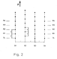
- FIG. 1 schematically shows a predefined "sawing image".
- F indicates the transport direction of the machine.
- the picture is from four sowing machines S1, S2, S3 and S4, the side by side on a common frame are attached, as the cited state of Technique describes in detail. It gets farther away assumed that every planter, starting from one with SL designated “start line”, seeds with a distance "a” stores. With proper functioning of the seeder results in the shendu shown in Figure 1.
- the single ones Seeds of the sowing units S1, S2, S3 and S4 are on each an imaginary line / along a row (R1, R2, R3, R4), where the distance from row to row is constant a (corresponding to the grain spacing to which the sowing units S1, S2, S3, S4 are set).
- the invention is based on the object, a seeder of offer generic type in which these disadvantages be avoided.
- a seeder is a predetermined Seed picture should be kept as precisely as possible.
- the seed drill should work in such a way that also irregular shecular can be precisely created. This applies, for example, to Applications in which with the grown from the seed Plants are then presented with "pictures" that go to Example from the air (from an airplane) recognized and as Advertising media can be used.
- the invention is based on the following consideration: Technology relates to seed drills, where the driveway than Reference variable is used. This guide is "One-dimensional”. The outlined disadvantages of the state of Technique can be avoided, provided a “2-dimensional "Not only in the direction of the track, but also “perpendicular to it", that is concretely: between neighboring sowing units.
- control also includes according to the invention corresponding "control”.
- seeding unit includes any technical embodiment a seed spreading agent, in particular Einzelkornsä sexualen.
- sowing units the arranged side by side along a corresponding frame (fastened) are mutually "linked” control technology.
- control of a sowing unit of the Control (position) of the adjacent sowing unit dependent.
- the Advantages of the invention can be exploited in a special way be when the controls (positions) of several sowing units with each other or with respect to a "main seeding unit” (Master sowing unit) are controlled.
- the advantages can be make optimal use of all sowing units with each other are networked control technology.
- the regulation may be so be designed so that it controls at least one sowing unit so that this seeding unit taking into account the position of Seed deposit of several adjacent sowing units the next Seeds off.
- the regulation / control so be interpreted that they set several sowing units so that each of these sowing units taking into account the position of Seed deposit of at least one adjacent sowing unit each depositing the next seed.
- the position of the seed deposit of at least one sowing unit can by an external system for determining the position of the last deposited seeds.
- fixed assignment systems such as GPS (global positioning system), DGPS (Differential global positioning system) or a laser positioning system. details arise from www.starlinkdgps.com with the proviso that the Determination accuracy is today in the cm to mm range.
- a corresponding system can be used both on the seeder itself, be set up as well as on an associated tractor.
- the regulation of the sowing unit can depend on the Position of the seed deposit of an adjacent sowing unit below Use of an angle sensor done. With this sensor can detect an angle and in an electrical signal size convert. These include: angle encoders, angle encoders, magnetic angle sensors, rotary potentiometers etc.
- the sowing units can (each) with a sensor for detection be equipped with the drop point of a seed. at Sowing units with seed discs, this can be a sensor for detection the angular position of the seed disc, for example the one mentioned Be an angle encoder.
- the seeder of Figure 3 includes example 4 again pressure differential S1 to S4, the distance "r" on a common Frame are attached.
- the direction of travel of the machine is indicated by arrow F.
- the sowing units S1 and S3 should, starting from the starting line SL, each at a distance "a" drop a seed. Accordingly, two form side by side lying seeds an imaginary line like R1.
- the sowing units S2 and S4 lay the first seed after "3 / 2a" from, then parallel to each other at a distance a, to a drilltruck reach, in which the deposited by S2, S4 grains each exactly at half the distance of the grains deposited by S1, S3 lie.
- Two adjacent seed grains of S1, S3 and S2, S4 each form an imaginary line such as R1, R1 '.
- FIG. 4 shows schematically a sowing image, which is provided with a seed drill The described type can be created. Where "A” is the working width the seeder with a variety of sowing units specified.
- F indicates the (meandering) direction of travel of the drill, for the first time during the journey designated "2" seed discharged from the sowing units to the "arm area” to form the figure to be created.
- track 4 will be accordingly, the seeds are placed so that they are in the desired assignment for later recognition of a header and Body part lie.
Abstract
Description
- mehrere Säaggregate sind im Abstand nebeneinander an einem Rahmen befestigt,
- jedes Säaggregat weist einen eigenen Antrieb zur Ablage von Saatgut auf,
- die Sämaschine umfaßt eine Regelung, die so ausgelegt ist, daß sie bei einem vorgegebenen Säbild entweder
- mindestens ein Säaggregat so regelt, daß dieses Säaggregat unter Berücksichtigung der Position der Saatgutablage mindestens eines benachbarten Säaggregates das Saatgut ablegt, oder
- alle Säaggregate zentral unter Verwendung eines externen Systems zur Positionsbestimmung jedes einzelnen Säaggregates geregelt werden.
Claims (7)
Applications Claiming Priority (2)
| Application Number | Priority Date | Filing Date | Title |
|---|---|---|---|
| DE2002151114 DE10251114B4 (de) | 2002-11-02 | 2002-11-02 | Sämaschine |
| DE10251114 | 2002-11-02 |
Publications (2)
| Publication Number | Publication Date |
|---|---|
| EP1415523A1 true EP1415523A1 (de) | 2004-05-06 |
| EP1415523B1 EP1415523B1 (de) | 2006-10-18 |
Family
ID=32087327
Family Applications (1)
| Application Number | Title | Priority Date | Filing Date |
|---|---|---|---|
| EP20030017336 Expired - Lifetime EP1415523B1 (de) | 2002-11-02 | 2003-07-31 | Sämaschine |
Country Status (4)
| Country | Link |
|---|---|
| EP (1) | EP1415523B1 (de) |
| AT (1) | ATE342651T1 (de) |
| DE (2) | DE10251114B4 (de) |
| DK (1) | DK1415523T3 (de) |
Cited By (17)
| Publication number | Priority date | Publication date | Assignee | Title |
|---|---|---|---|---|
| WO2006092133A1 (de) * | 2005-03-02 | 2006-09-08 | Wtk-Electronik Gmbh | Einzelkornsämaschine |
| WO2008065355A1 (en) * | 2006-11-27 | 2008-06-05 | Syngenta Participations Ag | Plant images |
| EP2227932A1 (de) | 2009-03-11 | 2010-09-15 | Deere & Company | Landwirtschaftliche Sämaschine |
| WO2012034754A1 (de) * | 2010-09-13 | 2012-03-22 | Lacos Computerservice Gmbh | Verfahren zum ausbringen von landwirtschaftlichen stoffen in kurven |
| WO2012115563A1 (en) * | 2011-02-23 | 2012-08-30 | Väderstad-Verken Ab | Agricultural machinery and procedure for such |
| EP2636292A1 (de) | 2012-03-09 | 2013-09-11 | Deere & Company | Anordnung und Verfahren zur Präzisionsaussaat von Saatkörnern |
| EP2870848A1 (de) | 2013-11-12 | 2015-05-13 | Dickey-John Corporation | Synchronisation eines Doppelreihensaatsystems |
| GB2527818A (en) * | 2014-07-03 | 2016-01-06 | Adcrop Ltd | Planting apparatus and methods |
| US10104836B2 (en) | 2014-06-11 | 2018-10-23 | John Paul Jamison | Systems and methods for forming graphical and/or textual elements on land for remote viewing |
| EP3530095A1 (de) * | 2018-02-21 | 2019-08-28 | Amazonen-Werke H. Dreyer GmbH & Co. KG | Sämaschine |
| EP3566558A1 (de) * | 2018-05-09 | 2019-11-13 | Deere & Company | Pflanzeinheit für eine sämaschine |
| EP3569045A1 (de) | 2018-05-15 | 2019-11-20 | Deere & Company | Verfahren und vorrichtung zum bearbeiten eines feldes mit pflanzenbewuchs |
| SE1950658A1 (sv) * | 2019-06-04 | 2020-12-05 | Vaederstad Holding Ab | Lantbruksredskap och förfarande för bestämning av rörelsetillstånd hos ett lantbruksredskap |
| WO2021073879A1 (de) * | 2019-10-17 | 2021-04-22 | Amazonen-Werke H. Dreyer Gmbh & Co. Kg | Landwirtschaftliche ausbringmaschine |
| WO2021104724A1 (de) * | 2019-11-25 | 2021-06-03 | Robert Bosch Gmbh | Verfahren zum ausbringen von saatgut und/oder setzlingen und landwirtschaftliche maschine |
| CN113170632A (zh) * | 2021-03-08 | 2021-07-27 | 中国农业大学 | 基于图像处理与变种播种技术的自走式田间图案播种机 |
| EP4056011A1 (de) * | 2021-03-10 | 2022-09-14 | Deere & Company | Pflanzmaschine und verfahren zum steuern derselben |
Families Citing this family (7)
| Publication number | Priority date | Publication date | Assignee | Title |
|---|---|---|---|---|
| DE102005010686B9 (de) * | 2004-03-16 | 2013-07-04 | Johannes Benninger | Verfahren zum Pflanzen von Sämlingen und/oder zur Direkt- oder Einzelkornsaat sowie zur Saat- und/oder Pflanzenpflege |
| EP2926640A1 (de) | 2014-04-04 | 2015-10-07 | Müller-Elektronik GmbH & Co. KG | Haltemodul zum Halten eines Antriebs für ein Einzelkornsägerät |
| DE102015217496A1 (de) | 2015-09-14 | 2017-03-16 | Deere & Company | Verfahren zum Ausbringen von Saatgutpartikeln oder Pflanzen auf ein Feld und eine entsprechende Maschine |
| CN107197644B (zh) * | 2016-03-16 | 2022-01-18 | 北京光和麦田科技有限公司 | 分选装置、播种机、分选控制系统及方法 |
| DE102016207510A1 (de) | 2016-05-02 | 2017-11-02 | Deere & Company | Pneumatische Drillmaschine |
| DE102016125453A1 (de) | 2016-12-22 | 2018-07-12 | Amazonen-Werke H. Dreyer Gmbh & Co. Kg | Landwirtschaftliche Einzelkornsämaschine und Verfahren |
| DE102020117911A1 (de) | 2020-07-07 | 2022-01-13 | Deere & Company | Verfahren zum Pflanzenanbau in einem regelmäßigen Muster mit standortangepasster Variation der Pflanzendichte |
Citations (5)
| Publication number | Priority date | Publication date | Assignee | Title |
|---|---|---|---|---|
| EP0592995B1 (de) | 1992-10-14 | 1996-06-19 | Franz Kleine Maschinenfabrik GmbH & Co. | Sämaschine für Einzelkornsaat |
| US5956255A (en) * | 1997-09-23 | 1999-09-21 | Case Corporation | Seed planter performance monitor |
| US6070539A (en) * | 1997-03-21 | 2000-06-06 | Case Corporation | Variable rate agricultural product application implement with multiple inputs and feedback |
| US20010000806A1 (en) * | 1999-11-01 | 2001-05-03 | Carr Brian W. | GPS system to provide planter tripping for crop research plots |
| DE10130182A1 (de) * | 2000-08-15 | 2002-02-28 | Amazonen Werke Dreyer H | Einzelkornsämaschine |
Family Cites Families (3)
| Publication number | Priority date | Publication date | Assignee | Title |
|---|---|---|---|---|
| DE4223585A1 (de) * | 1992-07-17 | 1994-01-20 | Amazonen Werke Dreyer H | Vorrichtung zum Ausbringen von landwirtschaftlichem Material |
| DE19921995A1 (de) * | 1999-05-12 | 2000-11-16 | Amazonen Werke Dreyer H | Vorrichtung zum Anschlußfahren |
| DE19958761A1 (de) * | 1999-12-08 | 2001-06-28 | Egon Fueglein | Positionierungs- und Bearbeitungssystem |
-
2002
- 2002-11-02 DE DE2002151114 patent/DE10251114B4/de not_active Expired - Fee Related
-
2003
- 2003-07-31 EP EP20030017336 patent/EP1415523B1/de not_active Expired - Lifetime
- 2003-07-31 AT AT03017336T patent/ATE342651T1/de active
- 2003-07-31 DE DE50305408T patent/DE50305408D1/de not_active Expired - Lifetime
- 2003-07-31 DK DK03017336T patent/DK1415523T3/da active
Patent Citations (5)
| Publication number | Priority date | Publication date | Assignee | Title |
|---|---|---|---|---|
| EP0592995B1 (de) | 1992-10-14 | 1996-06-19 | Franz Kleine Maschinenfabrik GmbH & Co. | Sämaschine für Einzelkornsaat |
| US6070539A (en) * | 1997-03-21 | 2000-06-06 | Case Corporation | Variable rate agricultural product application implement with multiple inputs and feedback |
| US5956255A (en) * | 1997-09-23 | 1999-09-21 | Case Corporation | Seed planter performance monitor |
| US20010000806A1 (en) * | 1999-11-01 | 2001-05-03 | Carr Brian W. | GPS system to provide planter tripping for crop research plots |
| DE10130182A1 (de) * | 2000-08-15 | 2002-02-28 | Amazonen Werke Dreyer H | Einzelkornsämaschine |
Cited By (26)
| Publication number | Priority date | Publication date | Assignee | Title |
|---|---|---|---|---|
| WO2006092133A1 (de) * | 2005-03-02 | 2006-09-08 | Wtk-Electronik Gmbh | Einzelkornsämaschine |
| WO2008065355A1 (en) * | 2006-11-27 | 2008-06-05 | Syngenta Participations Ag | Plant images |
| EP2227932A1 (de) | 2009-03-11 | 2010-09-15 | Deere & Company | Landwirtschaftliche Sämaschine |
| WO2012034754A1 (de) * | 2010-09-13 | 2012-03-22 | Lacos Computerservice Gmbh | Verfahren zum ausbringen von landwirtschaftlichen stoffen in kurven |
| WO2012115563A1 (en) * | 2011-02-23 | 2012-08-30 | Väderstad-Verken Ab | Agricultural machinery and procedure for such |
| US9119338B2 (en) | 2011-02-23 | 2015-09-01 | Väderstad-Verken Ab | Agricultural machinery and procedure for such |
| EP2636292A1 (de) | 2012-03-09 | 2013-09-11 | Deere & Company | Anordnung und Verfahren zur Präzisionsaussaat von Saatkörnern |
| DE102012203761A1 (de) | 2012-03-09 | 2013-09-12 | Deere & Company | Anordnung und Verfahren zur Präzisionsaussaat von Saatkörnern |
| AU2013201245B2 (en) * | 2012-03-09 | 2015-02-19 | Deere & Company | Assembly and method for the precision drilling of seed grains |
| US9320192B2 (en) | 2013-11-12 | 2016-04-26 | Dickey-John Corporation | Synchronization of a twin row planting system |
| EP2870848A1 (de) | 2013-11-12 | 2015-05-13 | Dickey-John Corporation | Synchronisation eines Doppelreihensaatsystems |
| US10104836B2 (en) | 2014-06-11 | 2018-10-23 | John Paul Jamison | Systems and methods for forming graphical and/or textual elements on land for remote viewing |
| GB2527818A (en) * | 2014-07-03 | 2016-01-06 | Adcrop Ltd | Planting apparatus and methods |
| EP3530095A1 (de) * | 2018-02-21 | 2019-08-28 | Amazonen-Werke H. Dreyer GmbH & Co. KG | Sämaschine |
| US11083127B2 (en) | 2018-05-09 | 2021-08-10 | Deere & Company | Seeding machine to provide transverse tramlines |
| EP3566558A1 (de) * | 2018-05-09 | 2019-11-13 | Deere & Company | Pflanzeinheit für eine sämaschine |
| EP4233512A3 (de) * | 2018-05-09 | 2023-11-08 | Deere & Company | Pflanzeinheit für eine sämaschine |
| EP4233511A3 (de) * | 2018-05-09 | 2023-11-08 | Deere & Company | Pflanzeinheit für eine sämaschine |
| US11134608B2 (en) | 2018-05-15 | 2021-10-05 | Deere & Company | Method and machine for plant cultivation on a field |
| EP3569045A1 (de) | 2018-05-15 | 2019-11-20 | Deere & Company | Verfahren und vorrichtung zum bearbeiten eines feldes mit pflanzenbewuchs |
| SE1950658A1 (sv) * | 2019-06-04 | 2020-12-05 | Vaederstad Holding Ab | Lantbruksredskap och förfarande för bestämning av rörelsetillstånd hos ett lantbruksredskap |
| WO2021073879A1 (de) * | 2019-10-17 | 2021-04-22 | Amazonen-Werke H. Dreyer Gmbh & Co. Kg | Landwirtschaftliche ausbringmaschine |
| US11785882B2 (en) | 2019-10-17 | 2023-10-17 | Amazonen-Werke H. Dreyer SE & Co. KG | Agricultural machine for synchronized seed and granulate application |
| WO2021104724A1 (de) * | 2019-11-25 | 2021-06-03 | Robert Bosch Gmbh | Verfahren zum ausbringen von saatgut und/oder setzlingen und landwirtschaftliche maschine |
| CN113170632A (zh) * | 2021-03-08 | 2021-07-27 | 中国农业大学 | 基于图像处理与变种播种技术的自走式田间图案播种机 |
| EP4056011A1 (de) * | 2021-03-10 | 2022-09-14 | Deere & Company | Pflanzmaschine und verfahren zum steuern derselben |
Also Published As
| Publication number | Publication date |
|---|---|
| DK1415523T3 (da) | 2007-02-19 |
| DE10251114A1 (de) | 2004-05-19 |
| ATE342651T1 (de) | 2006-11-15 |
| EP1415523B1 (de) | 2006-10-18 |
| DE10251114B4 (de) | 2006-04-13 |
| DE50305408D1 (de) | 2006-11-30 |
Similar Documents
| Publication | Publication Date | Title |
|---|---|---|
| EP1415523B1 (de) | Sämaschine | |
| EP2636292B1 (de) | Anordnung und Verfahren zur Präzisionsaussaat von Saatkörnern | |
| EP3000299B1 (de) | Verteilvorrichtung für körniges gut | |
| EP2932818B1 (de) | Verteilvorrichtung und Verfahren zum Ausbringen von granulatartigem Verteilgut | |
| DE102018111584A1 (de) | Pneumatische Einzelkornsämaschine | |
| DE2428485C2 (de) | Anordnung zur Abgabe von Saatgut | |
| DE102005010686B4 (de) | Verfahren zum Pflanzen von Sämlingen und/oder zur Direkt- oder Einzelkornsaat sowie zur Saat- und/oder Pflanzenpflege | |
| EP3530095A1 (de) | Sämaschine | |
| EP3338524A1 (de) | Landwirtschaftliche einzelkornsämaschine und verfahren | |
| EP1637026A1 (de) | Elektronische Überwachungseinrichtung | |
| DE2319721A1 (de) | Vorrichtung zum trennen einer mischung von materialien in zwei materialgruppen | |
| EP1856964A1 (de) | Sämaschine | |
| EP1884152B1 (de) | Einzelkornsämaschine | |
| DE2544888A1 (de) | Zufuehrvorrichtung | |
| DE2232674A1 (de) | Praezisionsantrieb fuer eine druckwalze | |
| EP0570792A1 (de) | Verfahren zum Anlegen von Markierungsstreifen mit einer Sämaschine | |
| DE2806275A1 (de) | Vorrichtung zum ordnen, ausrichten und lagerichtigen zufuehren von koerpern zu einer arbeitsstation | |
| DE102021113841A1 (de) | Bodenbearbeitungsgerät | |
| DE19845860A1 (de) | Elektronische Überwachungseinrichtung | |
| EP3409094B1 (de) | Verfahren zum planen und/oder ausführen eines düngungsvorgangs | |
| DE102019103233A1 (de) | Sämaschine | |
| AT500250B1 (de) | Verfahren und sämaschine zum ausbringen von saatgut auf ein feld | |
| EP4062733B1 (de) | Verfahren zum ermitteln der lage eines portionsschwerpunkts einer granulatportion | |
| DE10352208B4 (de) | Verfahren und Sämaschine zum Einbringen von Fahrgassenmarkierungen in ein Feld | |
| DE102004045724A1 (de) | Sensoreinheit für eine landwirtschaftliche Maschine |
Legal Events
| Date | Code | Title | Description |
|---|---|---|---|
| PUAI | Public reference made under article 153(3) epc to a published international application that has entered the european phase |
Free format text: ORIGINAL CODE: 0009012 |
|
| AK | Designated contracting states |
Kind code of ref document: A1 Designated state(s): AT BE BG CH CY CZ DE DK EE ES FI FR GB GR HU IE IT LI LU MC NL PT RO SE SI SK TR |
|
| AX | Request for extension of the european patent |
Extension state: AL LT LV MK |
|
| 17P | Request for examination filed |
Effective date: 20040420 |
|
| 17Q | First examination report despatched |
Effective date: 20040701 |
|
| AKX | Designation fees paid |
Designated state(s): AT BE BG CH CY CZ DE DK EE ES FI FR GB GR HU IE IT LI LU MC NL PT RO SE SI SK TR |
|
| GRAP | Despatch of communication of intention to grant a patent |
Free format text: ORIGINAL CODE: EPIDOSNIGR1 |
|
| GRAS | Grant fee paid |
Free format text: ORIGINAL CODE: EPIDOSNIGR3 |
|
| GRAA | (expected) grant |
Free format text: ORIGINAL CODE: 0009210 |
|
| AK | Designated contracting states |
Kind code of ref document: B1 Designated state(s): AT BE BG CH CY CZ DE DK EE ES FI FR GB GR HU IE IT LI LU MC NL PT RO SE SI SK TR |
|
| PG25 | Lapsed in a contracting state [announced via postgrant information from national office to epo] |
Ref country code: SK Free format text: LAPSE BECAUSE OF FAILURE TO SUBMIT A TRANSLATION OF THE DESCRIPTION OR TO PAY THE FEE WITHIN THE PRESCRIBED TIME-LIMIT Effective date: 20061018 Ref country code: SI Free format text: LAPSE BECAUSE OF FAILURE TO SUBMIT A TRANSLATION OF THE DESCRIPTION OR TO PAY THE FEE WITHIN THE PRESCRIBED TIME-LIMIT Effective date: 20061018 Ref country code: RO Free format text: LAPSE BECAUSE OF FAILURE TO SUBMIT A TRANSLATION OF THE DESCRIPTION OR TO PAY THE FEE WITHIN THE PRESCRIBED TIME-LIMIT Effective date: 20061018 Ref country code: IT Free format text: LAPSE BECAUSE OF FAILURE TO SUBMIT A TRANSLATION OF THE DESCRIPTION OR TO PAY THE FEE WITHIN THE PRESCRIBED TIME-LIMIT;WARNING: LAPSES OF ITALIAN PATENTS WITH EFFECTIVE DATE BEFORE 2007 MAY HAVE OCCURRED AT ANY TIME BEFORE 2007. THE CORRECT EFFECTIVE DATE MAY BE DIFFERENT FROM THE ONE RECORDED. Effective date: 20061018 Ref country code: IE Free format text: LAPSE BECAUSE OF FAILURE TO SUBMIT A TRANSLATION OF THE DESCRIPTION OR TO PAY THE FEE WITHIN THE PRESCRIBED TIME-LIMIT Effective date: 20061018 Ref country code: FI Free format text: LAPSE BECAUSE OF FAILURE TO SUBMIT A TRANSLATION OF THE DESCRIPTION OR TO PAY THE FEE WITHIN THE PRESCRIBED TIME-LIMIT Effective date: 20061018 Ref country code: CZ Free format text: LAPSE BECAUSE OF FAILURE TO SUBMIT A TRANSLATION OF THE DESCRIPTION OR TO PAY THE FEE WITHIN THE PRESCRIBED TIME-LIMIT Effective date: 20061018 |
|
| REG | Reference to a national code |
Ref country code: GB Ref legal event code: FG4D Free format text: NOT ENGLISH |
|
| REG | Reference to a national code |
Ref country code: IE Ref legal event code: FG4D Free format text: LANGUAGE OF EP DOCUMENT: GERMAN Ref country code: CH Ref legal event code: EP |
|
| REF | Corresponds to: |
Ref document number: 50305408 Country of ref document: DE Date of ref document: 20061130 Kind code of ref document: P |
|
| REG | Reference to a national code |
Ref country code: SE Ref legal event code: TRGR |
|
| PG25 | Lapsed in a contracting state [announced via postgrant information from national office to epo] |
Ref country code: BG Free format text: LAPSE BECAUSE OF FAILURE TO SUBMIT A TRANSLATION OF THE DESCRIPTION OR TO PAY THE FEE WITHIN THE PRESCRIBED TIME-LIMIT Effective date: 20070118 |
|
| PG25 | Lapsed in a contracting state [announced via postgrant information from national office to epo] |
Ref country code: ES Free format text: LAPSE BECAUSE OF FAILURE TO SUBMIT A TRANSLATION OF THE DESCRIPTION OR TO PAY THE FEE WITHIN THE PRESCRIBED TIME-LIMIT Effective date: 20070129 |
|
| GBT | Gb: translation of ep patent filed (gb section 77(6)(a)/1977) |
Effective date: 20070104 |
|
| PG25 | Lapsed in a contracting state [announced via postgrant information from national office to epo] |
Ref country code: PT Free format text: LAPSE BECAUSE OF FAILURE TO SUBMIT A TRANSLATION OF THE DESCRIPTION OR TO PAY THE FEE WITHIN THE PRESCRIBED TIME-LIMIT Effective date: 20070319 |
|
| REG | Reference to a national code |
Ref country code: IE Ref legal event code: FD4D |
|
| ET | Fr: translation filed | ||
| PLBE | No opposition filed within time limit |
Free format text: ORIGINAL CODE: 0009261 |
|
| STAA | Information on the status of an ep patent application or granted ep patent |
Free format text: STATUS: NO OPPOSITION FILED WITHIN TIME LIMIT |
|
| 26N | No opposition filed |
Effective date: 20070719 |
|
| REG | Reference to a national code |
Ref country code: CH Ref legal event code: PL |
|
| PG25 | Lapsed in a contracting state [announced via postgrant information from national office to epo] |
Ref country code: MC Free format text: LAPSE BECAUSE OF NON-PAYMENT OF DUE FEES Effective date: 20070731 Ref country code: LI Free format text: LAPSE BECAUSE OF NON-PAYMENT OF DUE FEES Effective date: 20070731 Ref country code: GR Free format text: LAPSE BECAUSE OF FAILURE TO SUBMIT A TRANSLATION OF THE DESCRIPTION OR TO PAY THE FEE WITHIN THE PRESCRIBED TIME-LIMIT Effective date: 20070119 Ref country code: CH Free format text: LAPSE BECAUSE OF NON-PAYMENT OF DUE FEES Effective date: 20070731 |
|
| PG25 | Lapsed in a contracting state [announced via postgrant information from national office to epo] |
Ref country code: EE Free format text: LAPSE BECAUSE OF FAILURE TO SUBMIT A TRANSLATION OF THE DESCRIPTION OR TO PAY THE FEE WITHIN THE PRESCRIBED TIME-LIMIT Effective date: 20061018 |
|
| PG25 | Lapsed in a contracting state [announced via postgrant information from national office to epo] |
Ref country code: LU Free format text: LAPSE BECAUSE OF NON-PAYMENT OF DUE FEES Effective date: 20070731 Ref country code: CY Free format text: LAPSE BECAUSE OF FAILURE TO SUBMIT A TRANSLATION OF THE DESCRIPTION OR TO PAY THE FEE WITHIN THE PRESCRIBED TIME-LIMIT Effective date: 20061018 |
|
| PG25 | Lapsed in a contracting state [announced via postgrant information from national office to epo] |
Ref country code: TR Free format text: LAPSE BECAUSE OF FAILURE TO SUBMIT A TRANSLATION OF THE DESCRIPTION OR TO PAY THE FEE WITHIN THE PRESCRIBED TIME-LIMIT Effective date: 20061018 Ref country code: HU Free format text: LAPSE BECAUSE OF FAILURE TO SUBMIT A TRANSLATION OF THE DESCRIPTION OR TO PAY THE FEE WITHIN THE PRESCRIBED TIME-LIMIT Effective date: 20070419 |
|
| REG | Reference to a national code |
Ref country code: FR Ref legal event code: PLFP Year of fee payment: 14 |
|
| REG | Reference to a national code |
Ref country code: FR Ref legal event code: PLFP Year of fee payment: 15 |
|
| REG | Reference to a national code |
Ref country code: FR Ref legal event code: PLFP Year of fee payment: 16 |
|
| PGFP | Annual fee paid to national office [announced via postgrant information from national office to epo] |
Ref country code: NL Payment date: 20210721 Year of fee payment: 19 |
|
| PGFP | Annual fee paid to national office [announced via postgrant information from national office to epo] |
Ref country code: AT Payment date: 20210722 Year of fee payment: 19 |
|
| REG | Reference to a national code |
Ref country code: AT Ref legal event code: PC Ref document number: 342651 Country of ref document: AT Kind code of ref document: T Owner name: KVERNELAND GROUP SOEST GMBH, DE Effective date: 20220411 |
|
| REG | Reference to a national code |
Ref country code: NL Ref legal event code: PD Owner name: KVERNELAND GROUP SOEST GMBH; DE Free format text: DETAILS ASSIGNMENT: CHANGE OF OWNER(S), ASSIGNMENT; FORMER OWNER NAME: KVERNELAND AS Effective date: 20220525 |
|
| REG | Reference to a national code |
Ref country code: GB Ref legal event code: 732E Free format text: REGISTERED BETWEEN 20220707 AND 20220713 |
|
| REG | Reference to a national code |
Ref country code: GB Ref legal event code: 732E Free format text: REGISTERED BETWEEN 20220728 AND 20220803 |
|
| REG | Reference to a national code |
Ref country code: DE Ref legal event code: R081 Ref document number: 50305408 Country of ref document: DE Owner name: KVERNELAND GROUP SOEST GMBH, DE Free format text: FORMER OWNER: KVERNELAND ASA, KVERNALAND, NO |
|
| PGFP | Annual fee paid to national office [announced via postgrant information from national office to epo] |
Ref country code: SE Payment date: 20220720 Year of fee payment: 20 Ref country code: GB Payment date: 20220722 Year of fee payment: 20 Ref country code: DK Payment date: 20220725 Year of fee payment: 20 Ref country code: DE Payment date: 20220620 Year of fee payment: 20 |
|
| PGFP | Annual fee paid to national office [announced via postgrant information from national office to epo] |
Ref country code: FR Payment date: 20220720 Year of fee payment: 20 Ref country code: BE Payment date: 20220720 Year of fee payment: 20 |
|
| REG | Reference to a national code |
Ref country code: BE Ref legal event code: PD Owner name: KVERNELAND AS; NO Free format text: DETAILS ASSIGNMENT: CHANGE OF OWNER(S), CHANGE OF LEGAL ENTITY; FORMER OWNER NAME: KVERNELAND AS Effective date: 20220630 |
|
| REG | Reference to a national code |
Ref country code: NL Ref legal event code: MM Effective date: 20220801 |
|
| REG | Reference to a national code |
Ref country code: AT Ref legal event code: MM01 Ref document number: 342651 Country of ref document: AT Kind code of ref document: T Effective date: 20220731 |
|
| PG25 | Lapsed in a contracting state [announced via postgrant information from national office to epo] |
Ref country code: AT Free format text: LAPSE BECAUSE OF NON-PAYMENT OF DUE FEES Effective date: 20220731 |
|
| PG25 | Lapsed in a contracting state [announced via postgrant information from national office to epo] |
Ref country code: NL Free format text: LAPSE BECAUSE OF NON-PAYMENT OF DUE FEES Effective date: 20220801 |
|
| REG | Reference to a national code |
Ref country code: DE Ref legal event code: R071 Ref document number: 50305408 Country of ref document: DE |
|
| REG | Reference to a national code |
Ref country code: DK Ref legal event code: EUP Expiry date: 20230731 |
|
| REG | Reference to a national code |
Ref country code: BE Ref legal event code: MK Effective date: 20230731 |
|
| REG | Reference to a national code |
Ref country code: GB Ref legal event code: PE20 Expiry date: 20230730 |
|
| REG | Reference to a national code |
Ref country code: SE Ref legal event code: EUG |
|
| PG25 | Lapsed in a contracting state [announced via postgrant information from national office to epo] |
Ref country code: GB Free format text: LAPSE BECAUSE OF EXPIRATION OF PROTECTION Effective date: 20230730 |