EP1413828A2 - Système d'échappement et procédé de fonctionnement d' une cheminée à parois doubles - Google Patents
Système d'échappement et procédé de fonctionnement d' une cheminée à parois doubles Download PDFInfo
- Publication number
- EP1413828A2 EP1413828A2 EP03024365A EP03024365A EP1413828A2 EP 1413828 A2 EP1413828 A2 EP 1413828A2 EP 03024365 A EP03024365 A EP 03024365A EP 03024365 A EP03024365 A EP 03024365A EP 1413828 A2 EP1413828 A2 EP 1413828A2
- Authority
- EP
- European Patent Office
- Prior art keywords
- pipe
- tube
- chimney
- exhaust
- auxiliary gas
- Prior art date
- Legal status (The legal status is an assumption and is not a legal conclusion. Google has not performed a legal analysis and makes no representation as to the accuracy of the status listed.)
- Withdrawn
Links
Images
Classifications
-
- F—MECHANICAL ENGINEERING; LIGHTING; HEATING; WEAPONS; BLASTING
- F23—COMBUSTION APPARATUS; COMBUSTION PROCESSES
- F23L—SUPPLYING AIR OR NON-COMBUSTIBLE LIQUIDS OR GASES TO COMBUSTION APPARATUS IN GENERAL ; VALVES OR DAMPERS SPECIALLY ADAPTED FOR CONTROLLING AIR SUPPLY OR DRAUGHT IN COMBUSTION APPARATUS; INDUCING DRAUGHT IN COMBUSTION APPARATUS; TOPS FOR CHIMNEYS OR VENTILATING SHAFTS; TERMINALS FOR FLUES
- F23L17/00—Inducing draught; Tops for chimneys or ventilating shafts; Terminals for flues
- F23L17/16—Induction apparatus, e.g. steam jet, acting on combustion products beyond the fire
-
- F—MECHANICAL ENGINEERING; LIGHTING; HEATING; WEAPONS; BLASTING
- F23—COMBUSTION APPARATUS; COMBUSTION PROCESSES
- F23J—REMOVAL OR TREATMENT OF COMBUSTION PRODUCTS OR COMBUSTION RESIDUES; FLUES
- F23J2213/00—Chimneys or flues
- F23J2213/20—Joints; Connections
- F23J2213/202—Joints; Connections between duct or stack sections
-
- F—MECHANICAL ENGINEERING; LIGHTING; HEATING; WEAPONS; BLASTING
- F23—COMBUSTION APPARATUS; COMBUSTION PROCESSES
- F23J—REMOVAL OR TREATMENT OF COMBUSTION PRODUCTS OR COMBUSTION RESIDUES; FLUES
- F23J2213/00—Chimneys or flues
- F23J2213/30—Specific materials
- F23J2213/303—Specific materials metallic
Definitions
- this tube element differs from other standard tube element components of the second tube only in the auxiliary gas supply connection. In principle, it can therefore be used anywhere in the exhaust system or exchanged for a relevant normal pipe element of the building system.
- the pipe element prepared with the auxiliary gas supply connection is, however, preferably a pipe element not far from the outlet side of the exhaust system, that is to say one of the uppermost pipe elements in the case of a vertical chimney arrangement.
- the auxiliary gas flow path between the auxiliary gas supply connection and the end outlet opening of the second tube is then relatively short.
- the space between the first tube and the second tube is filled with an insulating material, in particular mineral wool, in an area lying axially beyond the opening of the auxiliary gas supply connection into the second tube, as viewed from the opening at the end.
- an insulating material in particular mineral wool
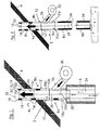
- the exhaust gas outlet opening of the first tube is positioned radially and axially within the second tube.
- Air is preferably used as the auxiliary gas, the auxiliary gas stream being generated from ambient air in the chimney arrangement by means of a blower arrangement. .
- the air supply operation i.e. the operation of the blower 30 in FIG. 1 or in FIG. 2, can take place, for example, in a controlled manner as a function of sensor-monitored conditions which influence the chimney draft, for example weather conditions, exhaust gas temperature conditions, pressure fluctuations, etc. there is sufficient chimney draft of the exhaust gas, the fan 30 can be switched to passive.
Landscapes
- Engineering & Computer Science (AREA)
- Chemical & Material Sciences (AREA)
- Combustion & Propulsion (AREA)
- Mechanical Engineering (AREA)
- General Engineering & Computer Science (AREA)
- Ventilation (AREA)
- Incineration Of Waste (AREA)
- Quick-Acting Or Multi-Walled Pipe Joints (AREA)
- Rigid Pipes And Flexible Pipes (AREA)
Applications Claiming Priority (2)
| Application Number | Priority Date | Filing Date | Title |
|---|---|---|---|
| DE20216502U | 2002-10-25 | ||
| DE20216502U DE20216502U1 (de) | 2002-10-25 | 2002-10-25 | Gasabsaugvorrichtung für eine Gasableitungsanlage |
Publications (2)
| Publication Number | Publication Date |
|---|---|
| EP1413828A2 true EP1413828A2 (fr) | 2004-04-28 |
| EP1413828A3 EP1413828A3 (fr) | 2008-06-11 |
Family
ID=31969859
Family Applications (1)
| Application Number | Title | Priority Date | Filing Date |
|---|---|---|---|
| EP03024365A Withdrawn EP1413828A3 (fr) | 2002-10-25 | 2003-10-24 | Système d'échappement et procédé de fonctionnement d' une cheminée à parois doubles |
Country Status (2)
| Country | Link |
|---|---|
| EP (1) | EP1413828A3 (fr) |
| DE (1) | DE20216502U1 (fr) |
Cited By (1)
| Publication number | Priority date | Publication date | Assignee | Title |
|---|---|---|---|---|
| FR2976329A1 (fr) * | 2011-06-07 | 2012-12-14 | Cmi Thermline Services | Dispositif aerodynamique de regulation de la temperature et de la pression dans un circuit de circulation de fluides |
Families Citing this family (3)
| Publication number | Priority date | Publication date | Assignee | Title |
|---|---|---|---|---|
| DE102007039984B4 (de) * | 2007-08-23 | 2015-11-12 | Truma Gerätetechnik GmbH & Co. KG | Abgasvorrichtung für eine Brenneinrichtung und ein Heizungssystem in einem Fahrzeug |
| DE202007017770U1 (de) | 2007-12-20 | 2009-04-23 | Kutzner + Weber Gmbh | Gasableitungsanordnung |
| CN106338081B (zh) * | 2016-11-03 | 2018-10-19 | 中国公路车辆机械有限公司 | 一种无接收室的双微可调节高温烟气引射器 |
Citations (2)
| Publication number | Priority date | Publication date | Assignee | Title |
|---|---|---|---|---|
| DE2230471A1 (de) | 1972-06-14 | 1974-11-14 | Sulzer Ag | Verfahren zum verkleinern der immissionen eines abgaskamins und vorrichtung zum durchfuehren des verfahrens |
| EP0798513B1 (fr) | 1996-03-23 | 2002-07-17 | Karl Schräder Nachfolger Inh. Karl-Heinz Schräder | Elément tubulaire à double paroi pour la fabrication de cheminées |
Family Cites Families (5)
| Publication number | Priority date | Publication date | Assignee | Title |
|---|---|---|---|---|
| BE381135A (fr) * | ||||
| GB190923791A (en) * | 1909-10-18 | 1910-09-15 | John Landells | Improvements relating to the Production of Induced Draught in Chimneys and the like. |
| US3586441A (en) * | 1967-07-12 | 1971-06-22 | Instrumentation Labor Inc | Atomic absorption spectroanalysis system |
| DE2817450A1 (de) * | 1978-04-21 | 1979-08-16 | Wolfgang Graffius | Radialgeblaese zum einbau in einen schornstein zur beschleunigung der rauchgase |
| GB8508275D0 (en) * | 1985-03-29 | 1985-05-09 | Kershaw C J | Chimney flues |
-
2002
- 2002-10-25 DE DE20216502U patent/DE20216502U1/de not_active Expired - Lifetime
-
2003
- 2003-10-24 EP EP03024365A patent/EP1413828A3/fr not_active Withdrawn
Patent Citations (2)
| Publication number | Priority date | Publication date | Assignee | Title |
|---|---|---|---|---|
| DE2230471A1 (de) | 1972-06-14 | 1974-11-14 | Sulzer Ag | Verfahren zum verkleinern der immissionen eines abgaskamins und vorrichtung zum durchfuehren des verfahrens |
| EP0798513B1 (fr) | 1996-03-23 | 2002-07-17 | Karl Schräder Nachfolger Inh. Karl-Heinz Schräder | Elément tubulaire à double paroi pour la fabrication de cheminées |
Cited By (3)
| Publication number | Priority date | Publication date | Assignee | Title |
|---|---|---|---|---|
| FR2976329A1 (fr) * | 2011-06-07 | 2012-12-14 | Cmi Thermline Services | Dispositif aerodynamique de regulation de la temperature et de la pression dans un circuit de circulation de fluides |
| EP2532960A3 (fr) * | 2011-06-07 | 2013-10-02 | Sa Cockerill Maintenance Et Ingenierie | Dispositif aérodynamique de régulation de la température et de la pression dans un circuit de circulation de fluides |
| BE1020814A5 (fr) * | 2011-06-07 | 2014-05-06 | Cockerill Maintenance & Ingenierie Sa | Dispositif aerodynamique de regulation de la temperature et de la pression dans un circuit de circulation de fluides. |
Also Published As
| Publication number | Publication date |
|---|---|
| DE20216502U1 (de) | 2004-02-26 |
| EP1413828A3 (fr) | 2008-06-11 |
Similar Documents
| Publication | Publication Date | Title |
|---|---|---|
| EP2336503A2 (fr) | Agencement d'évacuation d'air de ventilation séparé à partir d'un système d'aération des huiles lubrifiantes d'un turboréacteur | |
| EP1413828A2 (fr) | Système d'échappement et procédé de fonctionnement d' une cheminée à parois doubles | |
| WO2008113664A2 (fr) | Hotte aspirante | |
| EP2500663A1 (fr) | Installation de protection contre la fumée | |
| DE3643797A1 (de) | Atmosphaerisches gasheizgeraet mit externer abgasrueckfuehrung zur no(pfeil abwaerts)x(pfeil abwaerts)-reduzierung | |
| DE4238595C2 (de) | Modulare Lüftungseinheit mit integriertem Ventilator und angeschlossenem Filterrahmen, insbesondere für reinraumtechnische Zwecke | |
| DE3121467C1 (de) | Ventilator-Kühlturm mit mindestens einem drückenden Ventilator | |
| EP2175209B1 (fr) | Appareil de chauffage à valeur combustible | |
| DE202006011229U1 (de) | Ölbehälter mit Entlüftungssystem | |
| DE10255172A1 (de) | Raumlüftungsgerät | |
| DE2607712A1 (de) | Abluftmischhaube | |
| DE19950817A1 (de) | Dunstabzugsvorrichtung | |
| EP2539047A1 (fr) | Conduit et dispositif de collecte et d'évacuation d'un film marginal de condensat à implanter dans le conduit | |
| EP0330096B1 (fr) | Dispositif de purification de gaz | |
| DE19743591A1 (de) | Verfahren zur Stabilisierung der Triebwerks-Einlaufströmung bei Triebwerks-Standläufen | |
| EP2322870A1 (fr) | Chaudière à condensation | |
| DE102019107183B4 (de) | Ventilatorenanordnung und Entstaubungsanlage | |
| EP1845316A2 (fr) | Dispositif de traitement d'un gaz | |
| DE4219113C2 (de) | Vorrichtung zur Beeinflussung der Abgase von mit fossilen Brennstoffen betriebenen, raumluftunabhängigen Außenwand-Heizgeräten | |
| DE102010009347A1 (de) | Vorrichtung zum Waschen von Rauchgas | |
| WO2006037642A1 (fr) | Dispositif pour proteger les non-fumeurs | |
| EP3892919A1 (fr) | Dispositif de guidage d'écoulement permettant de guider au moins un écoulement de fluide dans la zone d'un dispositif de transport d'un appareil chauffant pour un bâtiment | |
| DE19904428C2 (de) | Maschinelle Rauch- und Wärmeabzugsanlage | |
| DE202022106948U1 (de) | Luftstrom-Filtermodul | |
| DE3539311A1 (de) | Schornstein-, lueftungs- und feuerungssystem |
Legal Events
| Date | Code | Title | Description |
|---|---|---|---|
| PUAI | Public reference made under article 153(3) epc to a published international application that has entered the european phase |
Free format text: ORIGINAL CODE: 0009012 |
|
| AK | Designated contracting states |
Kind code of ref document: A2 Designated state(s): AT BE BG CH CY CZ DE DK EE ES FI FR GB GR HU IE IT LI LU MC NL PT RO SE SI SK TR |
|
| AX | Request for extension of the european patent |
Extension state: AL LT LV MK |
|
| PUAL | Search report despatched |
Free format text: ORIGINAL CODE: 0009013 |
|
| AK | Designated contracting states |
Kind code of ref document: A3 Designated state(s): AT BE BG CH CY CZ DE DK EE ES FI FR GB GR HU IE IT LI LU MC NL PT RO SE SI SK TR |
|
| AX | Request for extension of the european patent |
Extension state: AL LT LV MK |
|
| 17P | Request for examination filed |
Effective date: 20081117 |
|
| AKX | Designation fees paid |
Designated state(s): AT BE BG CH CY CZ DE DK EE ES FI FR GB GR HU IE IT LI LU MC NL PT RO SE SI SK TR |
|
| 17Q | First examination report despatched |
Effective date: 20110329 |
|
| STAA | Information on the status of an ep patent application or granted ep patent |
Free format text: STATUS: THE APPLICATION IS DEEMED TO BE WITHDRAWN |
|
| 18D | Application deemed to be withdrawn |
Effective date: 20120503 |