EP1413828A2 - Exhaust system and method of operating a double-walled chimney pipe - Google Patents
Exhaust system and method of operating a double-walled chimney pipe Download PDFInfo
- Publication number
- EP1413828A2 EP1413828A2 EP03024365A EP03024365A EP1413828A2 EP 1413828 A2 EP1413828 A2 EP 1413828A2 EP 03024365 A EP03024365 A EP 03024365A EP 03024365 A EP03024365 A EP 03024365A EP 1413828 A2 EP1413828 A2 EP 1413828A2
- Authority
- EP
- European Patent Office
- Prior art keywords
- pipe
- tube
- chimney
- exhaust
- auxiliary gas
- Prior art date
- Legal status (The legal status is an assumption and is not a legal conclusion. Google has not performed a legal analysis and makes no representation as to the accuracy of the status listed.)
- Withdrawn
Links
Images
Classifications
-
- F—MECHANICAL ENGINEERING; LIGHTING; HEATING; WEAPONS; BLASTING
- F23—COMBUSTION APPARATUS; COMBUSTION PROCESSES
- F23L—SUPPLYING AIR OR NON-COMBUSTIBLE LIQUIDS OR GASES TO COMBUSTION APPARATUS IN GENERAL ; VALVES OR DAMPERS SPECIALLY ADAPTED FOR CONTROLLING AIR SUPPLY OR DRAUGHT IN COMBUSTION APPARATUS; INDUCING DRAUGHT IN COMBUSTION APPARATUS; TOPS FOR CHIMNEYS OR VENTILATING SHAFTS; TERMINALS FOR FLUES
- F23L17/00—Inducing draught; Tops for chimneys or ventilating shafts; Terminals for flues
- F23L17/16—Induction apparatus, e.g. steam jet, acting on combustion products beyond the fire
-
- F—MECHANICAL ENGINEERING; LIGHTING; HEATING; WEAPONS; BLASTING
- F23—COMBUSTION APPARATUS; COMBUSTION PROCESSES
- F23J—REMOVAL OR TREATMENT OF COMBUSTION PRODUCTS OR COMBUSTION RESIDUES; FLUES
- F23J2213/00—Chimneys or flues
- F23J2213/20—Joints; Connections
- F23J2213/202—Joints; Connections between duct or stack sections
-
- F—MECHANICAL ENGINEERING; LIGHTING; HEATING; WEAPONS; BLASTING
- F23—COMBUSTION APPARATUS; COMBUSTION PROCESSES
- F23J—REMOVAL OR TREATMENT OF COMBUSTION PRODUCTS OR COMBUSTION RESIDUES; FLUES
- F23J2213/00—Chimneys or flues
- F23J2213/30—Specific materials
- F23J2213/303—Specific materials metallic
Definitions
- this tube element differs from other standard tube element components of the second tube only in the auxiliary gas supply connection. In principle, it can therefore be used anywhere in the exhaust system or exchanged for a relevant normal pipe element of the building system.
- the pipe element prepared with the auxiliary gas supply connection is, however, preferably a pipe element not far from the outlet side of the exhaust system, that is to say one of the uppermost pipe elements in the case of a vertical chimney arrangement.
- the auxiliary gas flow path between the auxiliary gas supply connection and the end outlet opening of the second tube is then relatively short.
- the space between the first tube and the second tube is filled with an insulating material, in particular mineral wool, in an area lying axially beyond the opening of the auxiliary gas supply connection into the second tube, as viewed from the opening at the end.
- an insulating material in particular mineral wool
- the exhaust gas outlet opening of the first tube is positioned radially and axially within the second tube.
- Air is preferably used as the auxiliary gas, the auxiliary gas stream being generated from ambient air in the chimney arrangement by means of a blower arrangement. .
- the air supply operation i.e. the operation of the blower 30 in FIG. 1 or in FIG. 2, can take place, for example, in a controlled manner as a function of sensor-monitored conditions which influence the chimney draft, for example weather conditions, exhaust gas temperature conditions, pressure fluctuations, etc. there is sufficient chimney draft of the exhaust gas, the fan 30 can be switched to passive.
Abstract
Description
Die Erfindung betrifft eine Abgasanlage, umfassend eine doppelwandige Rohranordnung mit einem Abgas leitenden und eine Abgasaustrittsöffnung an einem axialen Ende aufweisenden ersten Rohr und einem das erste Rohr umgebenden und zusammen mit dem ersten Rohr einen Zwischenraum begrenzenden zweiten Rohr, welches eine axial endseitige Öffnung aufweist und sich mit dieser Öffnung bis in die Nähe der Abgasaustrittsöffnung am axialen Ende des ersten Rohres erstreckt, wobei die Rohre aus Komponenten eines Rohrbausystems, insbesondere Stecksystems, aneinander anschließbarer Rohrelemente gebildet sind.The invention relates to an exhaust gas system comprising a double-walled tube arrangement with an exhaust gas-conducting and an exhaust gas outlet opening at an axial end and a first tube surrounding the first tube and together with the first tube delimiting an intermediate space, which has an axially end-side opening and is extends with this opening into the vicinity of the exhaust gas outlet opening at the axial end of the first pipe, the pipes being formed from components of a pipe construction system, in particular a plug-in system, of pipe elements which can be connected to one another.
Solche doppelwandigen Abgasanlagen sind bekannt. Der Zwischenraum zwischen dem Innenrohr und dem Außenrohr ist bei konventionellen Systemen üblicherweise mit einem Dämmmaterial zur Wärmeisolation bzw. zur Schallisolation gefüllt. Ein Beispiel für ein solches konventionelles Kaminrohrbausystem mit durch Herstellung von Steckverbindungen aneinander anschließbaren Rohrelementen ist z.B. in der EP 0798513 B1 offenbart.Such double-walled exhaust systems are known. In conventional systems, the space between the inner tube and the outer tube is usually filled with an insulating material for heat insulation or for sound insulation. An example of such a conventional chimney pipe construction system with pipe elements which can be connected to one another by producing plug connections is e.g. disclosed in EP 0798513 B1.
Abgasanlagen aus solchen doppelwandigen Rohrelementen werden z.B. bei Regel-Feuerstätten, Niedertemperatur-Heizanlagen, Brennwert-Heizanlagen usw. verwendet.Exhaust systems from such double-walled pipe elements are e.g. used in standard fireplaces, low-temperature heating systems, condensing heating systems, etc.
Feuerstätten in einem Gebäude müssen an einer Abgasanlage angeschlossen sein, welche die Verbrennungsabgase von den Feuerstätten ins Freie ableiten. Aus Sicherheitsgründen sind an die Funktionszuverlässigkeit von Abgasanlagen sehr hohe Anforderungen gestellt. Wesentliches Element einer Abgasanlage ist der Schornstein bzw. Kamin, der auch bei ungünstigen Witterungsverhältnissen in der Lage sein sollte, die anstehenden Abgase direkt ins Freie abzuleiten. In Fällen, in denen der Abgastransport nicht durch den natürlichen Auftrieb erfolgen kann, weil der Schornsteinzug unzureichend ist, können bekanntermaßen Ventilatoren zur Abgasbeschleunigung in einer betreffenden Abgasleitung installiert sein. Die Ventilatoren im Abgasweg dienen dazu, die Abgasströmung zu erzwingen. Es ist auch bekannt, eine Ventilatorvorrichtung auf einem Schornsteinkopf zu installieren, um Abgase von unten anzusaugen und nach außen zu blasen.Fireplaces in a building must be connected to an exhaust system that discharges the combustion gases from the fireplaces to the outside. For safety reasons, very high demands are placed on the functional reliability of exhaust systems. An essential element of an exhaust system is the chimney or chimney, which should be able to discharge the upcoming exhaust gases directly into the open even in unfavorable weather conditions. In cases where the exhaust gas transport is not through the natural buoyancy can take place because the chimney draft is insufficient, it is known that fans for exhaust gas acceleration can be installed in a relevant exhaust pipe. The fans in the exhaust gas path serve to force the exhaust gas flow. It is also known to install a fan device on a chimney head in order to suck in exhaust gases from below and to blow them outwards.
Die vorstehend angesprochenen Probleme treten in ähnlicher Weise auch bei Lüftungsanlagen für die Be- und Entlüftung von Badezimmern, WC-Räumen, Küchen, Laborräumen usw. auf. Zur Sicherstellung des zuverlässigen Transportes der Abluft über Lüftungsschächte bzw. Entlüftungsleitungen ist man auch bereits dazu übergegangen, Ventilatoren in die Lüftungsleitung einzusetzen, um damit eine Strömung der Abluft nach außen hin zu erzwingen. Im Sinne der vorliegenden Anmeldung sollen auch solche Lüftungsanlagen unter den Begriff Abgasanlagen zu subsummieren sein.The problems mentioned above also occur in a similar manner in ventilation systems for the ventilation of bathrooms, toilet rooms, kitchens, laboratory rooms, etc. In order to ensure the reliable transport of the exhaust air via ventilation shafts or ventilation ducts, it has already started to use fans in the ventilation duct in order to force the flow of the exhaust air to the outside. In the sense of the present application, such ventilation systems should also be subsumed under the term exhaust systems.
Insbesondere bei Abgasanlagen von Feuerstätten tritt häufig der Fall auf, dass unter normalen Witterungsbedingungen der thermische Auftrieb im Schornstein, also der Schornsteinzug, ausreichen würde, um eine zuverlässige Abgasableitung sicherzustellen, so dass nur gelegentlich bei ungünstigen Witterungsverhältnissen eine ventilatorische Zwangsabsaugung erforderlich ist. Da bei herkömmlichen Abgasanlagen der Ventilator bzw. das Gebläse im Gasableitungsweg des Schornsteins installiert ist und dort einen relativ großen Strömungwiderstand bildet, kann der Schornsteinzug durch das Vorhandensein des Ventilators wesentlich beeinträchtigt sein, was in vielen Fällen darauf hinausläuft, dass der Ventilator im Dauerbetrieb laufen muss, also auch in den Phasen, in denen der thermische Auftrieb bei Nichtvorhandensein des Ventilators dazu ausreichen ausreichen würde, die Abgase ins Freie auszubringen.Particularly in the case of flue gas systems from fireplaces, it is often the case that, under normal weather conditions, the thermal lift in the chimney, i.e. the chimney draft, would be sufficient to ensure reliable flue gas discharge, so that forced ventilation is only occasionally necessary in unfavorable weather conditions. Since in conventional exhaust systems the fan or blower is installed in the gas discharge path of the chimney and forms a relatively large flow resistance there, the chimney draft can be significantly impaired by the presence of the fan, which in many cases means that the fan must run in continuous operation , also in the phases in which the thermal uplift would be sufficient to discharge the exhaust gases outdoors if the fan were not present.
Der Dauerbetrieb des Ventilators verursacht erhöhte Energiekosten. Überdies sind Ventilatoren in dem Gasableitungsweg Verschmutzung durch Verbrennungsrückstände oder durch sonstige im Gasstrom mitgeführte Partikel ausgesetzt. Dies bedeutet einen erhöhten Verschleiß und eine erhöhte Wartungsanfälligkeit des Ventilators. Schließlich bedeutet ein Gebläse bzw. ein Ventilator im Abgasströmungsweg eine Erschwernis für den Schornsteinfeger beim Reinigen des Schornsteins.Continuous operation of the fan causes increased energy costs. In addition, fans in the gas discharge path are exposed to contamination from combustion residues or other particles entrained in the gas flow. This means increased wear and increased maintenance of the fan. Finally, a blower or a fan in the exhaust gas flow path makes it difficult for the chimney sweep to clean the chimney.
Es sind auch bereits Vorschläge gemacht worden, am Kopf eines Schornsteins ein Injektor-Absauggerät zu installieren, welches Umgebungsluft ansaugt und in einem die vom Schornstein abgegebene Rauchsäule umgebenden Luftstrom nach oben abgibt. Der mit relativ hoher Strömungsgeschwindigkeit aufsteigende Luftstrom stabilisiert die Rauchsäule und sorgt für einen Sogeffekt an der Austrittsöffnung des Schornsteins. Die bekannt gewordenen Lösungen dieser Art sind teils aufwendig und wirken optisch unschön. Es ist auch bereits vorgeschlagen worden, einen Kamin zu ummanteln und den dabei entstehenden Ringkanal dazu zu nutzen, die von einem am Boden aufgestellten Gebläse geförderte Luft durch den Ringkanal zur Kaminkrone zu führen (vgl. DE-OS 2230471). Eine solche Lösung hat sich jedoch nicht durchsetzen können, da sie mit diversen Nachteilen behaftet ist. So führt der über die gesamte Kaminlänge den Kamin außen streifenden Luftstrom zu einer Kühlung des Kamins und des darin aufsteigenden Abgases mit der Folge, dass der Kamin weniger gut zieht und die Gefahr der Abgaskondensation an der Kamininnenwand steigt. Im Hinblick auf das Ziel, die Abgase effizienter aus dem Kamin auszubringen, ist die vorstehend genannte Lösung in gewissem Maße sogar kontraproduktiv bzw. nur dann wirksam, wenn ein sehr starker Luftstrom am Kaminausgang herrscht. Hierzu bedarf es jedoch eines sehr starken Gebläses, welches einen Luftstrom erzeugen kann, der nicht nur den relativ hohen Strömungswiderstand des Ringraumes über die gesamte Kaminlänge überwindet, sondern darüber hinaus am Kaminausgang noch den angestrebten Injektor-Effekt zur Verbesserung des Kaminzuges hervorrufen kann. Ein weiterer Nachteil der letztgenannten Lösung besteht darin, dass sie normalerweise einen großen baulichen Aufwand erfordert und als günstige Nachrüstlösung in den meisten Fällen überhaupt nicht in Frage kommt.Proposals have also already been made to install an injector suction device on the top of a chimney, which sucks in ambient air and emits it upward in an air flow surrounding the column of smoke emitted by the chimney. The air flow, which rises at a relatively high flow rate, stabilizes the smoke column and provides a suction effect at the outlet opening of the chimney. The known solutions of this type are sometimes complex and look unattractive. It has also already been proposed to encase a chimney and to use the resulting ring channel to guide the air conveyed by a fan placed on the floor through the ring channel to the chimney crown (cf. DE-OS 2230471). However, such a solution has not been able to prevail because it has various disadvantages. The air stream that grazes the outside of the chimney over the entire length of the chimney cools the chimney and the exhaust gas rising in it, with the result that the chimney draws less well and the risk of exhaust gas condensation on the inside of the chimney increases. With regard to the goal of removing the exhaust gases more efficiently from the chimney, the above-mentioned solution is to some extent even counterproductive or only effective if there is a very strong air flow at the chimney outlet. However, this requires a very powerful fan, which can generate an air flow that not only overcomes the relatively high flow resistance of the annulus over the entire length of the chimney, but can also cause the desired injector effect at the chimney exit to improve the chimney draft. Another disadvantage of the latter solution is that it usually requires a great deal of construction and is in most cases out of the question as a cheap retrofit solution.
Der Erfindung liegt die Aufgabe zugrunde, eine Gasableitungsanlage der eingangs genannten Art bereitzustellen, welche auf einfache Weise installierbar ist und mit einfachen Mitteln eine wirksame Unterstützung des Zuges des Abgas führenden ersten Rohres ermöglicht, ohne dass dafür optisch auffällige Installationen am Kaminkopf erforderlich sind, und welche als Nachrüstsystem für einen vorhandenen konventionellen Kamin einsetzbar ist.The invention has for its object to provide a gas discharge system of the type mentioned, which can be installed in a simple manner and with simple means enables effective support of the train of the exhaust pipe carrying the first pipe without the need for optically conspicuous installations on the chimney head, and which can be used as a retrofit system for an existing conventional fireplace.
Zur Lösung dieser Aufgabe wird erfindungsgemäß vorgeschlagen, dass wenigstens ein Rohrelement des zweiten Rohres einen Hilfsgaszuführungsanschluss, insbesondere Luftzuführungsanschluss, aufweist, an dem eine Hilfsgasstromerzeugungseinrichtung angeschlossen ist, so dass bei Betrieb der Hilfsgasstromerzeugungseinrichtung ein erzwungener Hilfsgasstrom in dem Zwischenraum zur endseitigen Öffnung des zweiten Rohres und somit zum Randbereich der Abgasaustrittsöffnung des ersten Rohres mit einer in Bezug auf die Abgasaustrittsöffnung axial nach außen gerichteten Strömungskomponente stattfindet.To solve this problem, the invention proposes that at least one pipe element of the second pipe has an auxiliary gas supply connection, in particular an air supply connection, to which an auxiliary gas flow generating device is connected, so that during operation of the auxiliary gas flow generating device, a forced auxiliary gas flow in the intermediate space to the end opening of the second pipe and thus to the edge region of the exhaust gas outlet opening of the first pipe with a takes place axially outward flow component with respect to the exhaust gas outlet opening.
Gemäß einer bevorzugten Ausführungsform der Erfindung unterscheidet sich dieses Rohrelement von anderen Standard-Rohrelementkomponenten des zweiten Rohres nur durch den Hilfsgaszuführungsanschluss. Es kann daher prinzipiell an beliebiger Stelle der Abgasanlage eingesetzt bzw. gegen ein betreffendes Normalrohrelement des Bausystems ausgetauscht werden. Zur Vermeidung der oben in Bezug auf den Stand der Technik genannten Nachteile ist das mit dem Hilfsgaszuführungsanschluss präparierte Rohrelement jedoch vorzugsweise ein nicht weit von der Austrittsseite der Abgasanlage entferntes Rohrelement, also im Falle einer vertikalen Kaminanordnung eines der obersten Rohrelemente. Der Hilfsgasströmungsweg zwischen dem Hilfsgaszuführungsanschluss und der endseitigen Austrittsöffnung des zweiten Rohres ist dann relativ kurz. Der Strömungswiderstand des Zwischenraums für den Hilfsgasstrom ist daher klein, so dass zur Erzeugung eines an der Abgasaustrittsöffnung hinreichend starken Hilfsgasstroms ein kleineres Gebläse mit relativ geringem Energiebedarf ausreicht. Da der Hilfsgasstrom im Übrigen auch nur über eine relativ kleine Strecke das Abgas führende Rohr streift, kommt es auch nicht in nennenswertem Maße zu einem Auskühleffekt des ersten Rohres. Sofern es sich bei den Rohrelementen um solche handelt, die bereits mit einer Isolationsfüllung des Zwischenraumes vorpräpariert sind, so ist lediglich dafür Sorge zu tragen, dass zwischen der Austrittsseite der Abgasanlage und dem Hilfsgaszuführungsanschluss das Isolationsmaterial wenigstens teilweise entfernt ist, damit der Hilfsgasstrom einen freien Weg vom Hilfsgaszuführungsanschluss zur Austrittsseite hat. Im Übrigen kann jedoch unterhalb des Hilfsgaszuführungsanschlusses der Zwischenraum zwischen dem ersten Rohr und dem zweiten Rohr mit Dämmmaterial zur Wärmeisolierung oder zur Schallisolierung ausgefüllt sein.According to a preferred embodiment of the invention, this tube element differs from other standard tube element components of the second tube only in the auxiliary gas supply connection. In principle, it can therefore be used anywhere in the exhaust system or exchanged for a relevant normal pipe element of the building system. To avoid the disadvantages mentioned above in relation to the prior art, the pipe element prepared with the auxiliary gas supply connection is, however, preferably a pipe element not far from the outlet side of the exhaust system, that is to say one of the uppermost pipe elements in the case of a vertical chimney arrangement. The auxiliary gas flow path between the auxiliary gas supply connection and the end outlet opening of the second tube is then relatively short. The flow resistance of the intermediate space for the auxiliary gas flow is therefore small, so that a smaller fan with a relatively low energy requirement is sufficient to generate a sufficiently strong auxiliary gas flow at the exhaust gas outlet opening. Since the auxiliary gas flow also only touches the pipe carrying the exhaust gas over a relatively small distance, there is no significant cooling effect of the first pipe. If the pipe elements are those that are already prepared with an insulation filling of the intermediate space, it is only necessary to ensure that the insulation material between the outlet side of the exhaust system and the auxiliary gas supply connection is at least partially removed, so that the auxiliary gas flow is clear from the auxiliary gas supply connection to the outlet side. Otherwise, however, the space between the first pipe and the second pipe below the auxiliary gas supply connection can be filled with insulating material for heat insulation or for sound insulation.
Das die Austrittsseite der Rohranordnung aufweisende Rohrelemente kann das mit dem Hilfsgaszuführanschluss ausgebildete Rohrelement sein und somit zur Bildung der Kaminkrone beitragen, ohne diese von der optischen Gestalt her ungewöhnlich zu verändern. Vorzugsweise wird das mit dem Hilfsgaszuführanschluss ausgestattete Rohrelement jedoch in einer Kaminkonstruktion nicht das oberste, den Kaminausgang definierende Rohrelemente, sondern ein diesem nächst benachbart oder übernächst benachbart darunter liegendes Rohrelement. In dem häufig vorkommenden Fall, dass die als Kaminabschnitt mit doppelter Wand ausgebildete Abgasanlage ein Gebäudedach durchsetzt, kann dann auf einfache Weise das mit dem Hilfsgaszuführanschluss versehene Rohrelement im Gebäude, also unter dem Dach vorgesehen sein. Ein ggf. unmittelbar an dem Hilfsgaszuführanschluss angeschlossenes Gebläse ist somit geschützt unter dem Dach angeordnet.The pipe elements having the outlet side of the pipe arrangement can be the tubular element formed with the auxiliary gas supply connection and thus contribute to the formation of the chimney crown without changing the optical shape in an unusual manner. In a chimney construction, however, the pipe element equipped with the auxiliary gas supply connection preferably does not become the uppermost pipe element defining the chimney exit, but rather a pipe element lying next to it or next to it next to it. In the frequently occurring case that the exhaust system designed as a chimney section with a double wall penetrates a building roof, the tubular element provided with the auxiliary gas supply connection can then be provided in the building, that is to say under the roof. A blower, which may be connected directly to the auxiliary gas supply connection, is thus protected under the roof.
Eine interessante Anwendungsmöglichkeit der Abgasanlage nach der Erfindung ist es, sie als Verlängerung eines konventionellen Kamins, insbesondere eines Stumpfes eines solchen konventionellen Kamins zu installieren, um diesem konventionellen Kamin einen besseren Zug zu verleihen.An interesting application of the exhaust system according to the invention is to install it as an extension of a conventional chimney, in particular a stump of such a conventional chimney, in order to give this conventional chimney a better draft.
Es wird auch bei der erfindungsgemäßen Abgasanlage von dem Effekt Gebrauch gemacht, dass die erzwungene schnelle Strömung des Hilfsgases in unmittelbarer Nachbarschaft zur Ausmündung des Leitungsendabschnitts des ersten Rohres einen statischen Unterdruck und somit einen Sog auf das Abgas in dem Leitungsendabschnitt des ersten Rohres erzeugt. Die Wirkungsweise entspricht somit im Wesentlichen dem Injektor-Prinzip, wie es ähnlich z.B. bei Wasserstrahlpumpen angewendet wird. Da das Hilfsgas, vorzugsweise Luft, extern, also außerhalb des Abgas führenden ersten Rohres zu dem Randbereich der Abgasaustrittsöffnung geleitet wird, sind keine Komponenten erforderlich, die in das Abgas führende erste Rohr hineinragen. Der Strömungswiderstand des ersten Rohres wird somit durch die Maßnahmen zur Nutzung des Injektor-Prinzips nicht erhöht.In the exhaust system according to the invention, use is made of the effect that the forced rapid flow of the auxiliary gas in the immediate vicinity of the mouth of the line end section of the first pipe generates a static vacuum and thus a suction on the exhaust gas in the line end section of the first pipe. The mode of operation essentially corresponds to the injector principle, as is similar to e.g. is used in water jet pumps. Since the auxiliary gas, preferably air, is conducted externally, ie outside the first pipe carrying the exhaust gas, to the edge region of the exhaust gas outlet opening, no components are required which protrude into the first pipe carrying the exhaust gas. The flow resistance of the first tube is therefore not increased by the measures for using the injector principle.
Der Hilfsgaszufuhrbetrieb kann normalerweise auf Phasen beschränkt werden, in denen der normale Schornsteinzug, also der thermische Auftrieb der Abgase im ersten Rohr zu schwach ist, um eine sichere Abgasableitung zu gewährleisten.The auxiliary gas supply operation can normally be limited to phases in which the normal chimney draft, i.e. the thermal lift of the exhaust gases in the first pipe, is too weak to ensure safe exhaust gas discharge.
Bei dem Hilfsgas handelt es sich zweckmäßigerweise um Umgebungsluft, wobei die Hilfsgasstromerzeugungseinrichtung wenigstens ein Luftansauggerät, insbesondere ein Gebläse bzw. Ventilator zum Ansaugen der Umgebungsluft und zur Einleitung der angesaugten Luft in den Zwischenraum zwischen dem ersten Rohr und dem zweiten Rohr durch den Luftzuführanschluss hindurch aufweist.The auxiliary gas is expediently ambient air, the auxiliary gas flow generating device having at least one air suction device, in particular a blower or fan for sucking in the ambient air and for introducing the sucked-in air into the intermediate space between the first tube and the second tube through the air supply connection.
Der von dem Zwischenraum gebildete Kanal ist normalerweise so gestaltet, dass er zumindest den Leitungsendabschnitt des ersten Rohres im Wesentlichen konzentrisch umgibt, so dass eine Hilfsgasströmung um den gesamten Randbereich der Gasaustrittsöffnung des Leitungsendabschnittes herumauftritt und insoweit in Bezug auf den Leitungsendabschnitt und die Gasaustrittsöffnung näherungsweise axialsymmetrische Ansaugverhältnisse gegeben sind, welche bei einem vertikalen Kamin das Ausbringen der Abgase in vertikaler Richtung begünstigen. Auf diese Weise ist eine Stabilisierung der Rauchgassäule über der Schornsteinausmündung erzielbar, was theoretisch einer Erhöhung des Schornsteins entspricht.The channel formed by the intermediate space is normally designed in such a way that it surrounds at least the line end section of the first tube essentially concentrically, so that an auxiliary gas flow occurs around the entire edge region of the gas outlet opening of the line end section and in this respect approximately axially symmetrical suction conditions with respect to the line end section and the gas outlet opening are given, which favor the discharge of the exhaust gases in the vertical direction in a vertical chimney. In this way, a stabilization of the flue gas column above the chimney outlet can be achieved, which theoretically corresponds to an increase in the chimney.
Ein Vorteil der Erfindung liegt noch darin, dass das Gerät zur Erzeugung der erzwungenen Strömung des Hilfsgases mit dem abzuleitenden Abgas, also etwa Verbrennungsgas, normalerweise nicht in Kontakt kommt und somit der Gefahr einer aggressiven Verschmutzung und eines erhöhten Verschleißes nicht ausgesetzt ist.Another advantage of the invention is that the device for generating the forced flow of the auxiliary gas does not normally come into contact with the exhaust gas to be discharged, that is to say combustion gas, and is therefore not exposed to the risk of aggressive contamination and increased wear.
Wenngleich in einer speziellen Variante der Erfindung das Hilfsgas z.B. ein Abgas aus einer anderen Abgasquelle sein kann, welches im Überdruck durch den Zwischenraum hindurch nach oben ausgebracht wird, so kommt als Hilfsgas in der bevorzugten Ausführungsform der Erfindung Luft, nämlich angesaugte Umgebungsluft, in Frage.Although in a special variant of the invention the auxiliary gas e.g. can be an exhaust gas from another exhaust gas source, which is discharged in excess pressure through the intermediate space upwards, so air, namely ambient air drawn in, comes into consideration as auxiliary gas in the preferred embodiment of the invention.
Der Hilfsgaszuführungsanschluss ist vorzugsweise ein schräg zur Achse des zweiten Rohres außen an dem zweiten Rohr angeordneter und darin mündender Stutzen. Das mit dem Hilfsgaszuführungsanschluss versehene Rohrelement des zweiten Rohres ist gemäß einer bevorzugten Ausführungsform der Erfindung an beiden axialen Enden mit einem jeweiligen Nachbarrohrelement des zweiten Rohres verbundenes Zwischenrohrelement.The auxiliary gas supply connection is preferably a connecting piece arranged at an angle to the axis of the second tube on the outside of the second tube and opening therein. According to a preferred embodiment of the invention, the tube element of the second tube provided with the auxiliary gas supply connection is an intermediate tube element connected to a respective neighboring tube element of the second tube at both axial ends.
Vorzugsweise sind die jeweils seitlich bzw. radial einander benachbarten Abschnitte des ersten Rohres und des zweiten Rohres gemeinsam zu zusammenhängend montierbaren Komponenten des Kaminrohrbausystems zusammengefasst, wobei eine dieser zusammenhängend montierbaren Komponenten den Hilfsgaszuführungsanschluss aufweist.Preferably, the laterally or radially adjacent sections of the first pipe and the second pipe are combined to form coherently mountable components of the chimney pipe system, one of these coherently mountable components having the auxiliary gas supply connection.
Die Hilfsgasstromerzeugungseinrichtung ist vorzugsweise ein Gebläse zum Ansaugen von Umgebungsluft, wobei ein solches Gebläse beispielsweise unmittelbar an dem Hilfsgaszuführungsanschluss angeschlossen sein kann.The auxiliary gas flow generating device is preferably a blower for drawing in ambient air, it being possible for such a blower to be connected, for example, directly to the auxiliary gas supply connection.
Die Rohrelelementkomponenten weisen gemäß einer Weiterbildung der Erfindung einander komplementäre Steckverbindungsenden, nämlich jeweils ein Einsteckende und ein Muffenende auf und sind durch Steckverbindungen aneinander angeschlossen. Die Steckverbindungsenden der Rohrelemente des ersten Rohres oder/und die Steckverbindungsenden der Rohrelemente des zweiten Rohres sind vorzugsweise konisch geformt. Derartige Steckverbindungen sind z.B. aus der EP 0798513 B1 bekannt.According to a development of the invention, the tubular element components have mutually complementary plug-in connection ends, namely in each case one plug-in end and one socket end, and are connected to one another by plug-in connections. The connector ends of the tube elements of the first tube and / or the connector ends of the tube elements of the second tube are preferably conically shaped. Such connectors are e.g. known from EP 0798513 B1.
Als Verbindungstechniken kommen alternativ oder zusätzlich z.B. Schraubverbindungstechniken, bajonettverschlussartige Verbindungen usw. in Frage.As connection techniques, alternatively or additionally, e.g. Screw connection techniques, bayonet-type connections etc. in question.
Der Zwischenraum zwischen dem ersten Rohr und dem zweiten Rohr ist gemäß einer Weiterbildung der Erfindung in einem - von der endseitigen Öffnung her betrachtet - axial jenseits der Einmündung des Hilfsgaszuführungsanschlusses in das zweite Rohr liegenden Bereich mit einem Dämmmaterial, insbesondere Mineralwolle, gefüllt.According to a development of the invention, the space between the first tube and the second tube is filled with an insulating material, in particular mineral wool, in an area lying axially beyond the opening of the auxiliary gas supply connection into the second tube, as viewed from the opening at the end.
Die Rohrelementkomponenten sind vorzugsweise aus Metallblech, insbesondere Edelstahl, gebildet.The tubular element components are preferably made of sheet metal, in particular stainless steel.
Gemäß einer Ausführungsform der Erfindung ist die Abgasanlage auf einem Kaminstumpf aufgesetzt, wobei das erste Rohr - nicht aber das zweite Rohr zur Ableitung von Abgas aus dem Kaminstumpf mit diesem kommuniziert.According to one embodiment of the invention, the exhaust system is placed on a stump, the first pipe, but not the second pipe, for communicating exhaust gas from the stump communicating with the latter.
Gemäß einer anderen Ausführungsform der Erfindung ist die Rohranordnung Teil eines insgesamt aus Komponenten des Kaminbausystems hergestellten Kamins.According to another embodiment of the invention, the pipe arrangement is part of a chimney made entirely of components of the chimney construction system.
Der die Austrittsöffnungen aufweisende Endabschnitt der Rohranordnung und der mit dem Hilfsgaszuführungsanschluss versehene Abschnitt der Rohranordnung sind vorzugsweise von verschiedenen Komponenten des Kaminrohrbausystems gebildet.The end section of the pipe arrangement which has the outlet openings and the section of the pipe arrangement which is provided with the auxiliary gas supply connection are preferably formed by various components of the chimney pipe construction system.
Gemäß einer Weiterbildung der Erfindung ist die Abgasaustrittsöffnung des ersten Rohres radial und axial innerhalb des zweiten Rohrs positioniert.According to a development of the invention, the exhaust gas outlet opening of the first tube is positioned radially and axially within the second tube.
Gegenstand der Erfindung ist auch ein Verfahren zum Betreiben einer aus Komponenten eines Kaminrohrbausystems aneinander anschließbarer Rohrelemente gebildeten doppelwandigen Kaminanordnung mit einem Abgas leitenden und eine Abgasaustrittsöffnung an einem axialen Ende aufweisenden ersten Rohr und einem das erste Rohr insbesondere konzentrisch umgebenden und zusammen mit dem ersten Rohr einen Zwischenraum begrenzenden zweiten Rohr, welches eine axial endseitige Öffnung aufweist und sich mit dieser Öffnung bis in die Nähe der Abgasaustrittsöffnung am axialen Ende des ersten Rohres erstreckt. Das Verfahren ist dadurch gekennzeichnet, dass ein Hilfsgasstrom, insbesondere Luftstrom, erzeugt - und in dem Zwischenraum zur endseitigen Öffnung des zweiten Rohres und somit zum Randbereich der Abgasaustrittsöffnung des ersten Rohres mit einer in Bezug auf die Abgasaustrittsöffnung axial nach außen gerichteten Strömungskomponente geleitet wird. Das Verfahren kann bei konventionellen doppelwandigen Kaminrohren angewendet werden, wobei dafür Sorge getragen werden muss, dass ab der Stelle, an der das Hilfsgas in den Zwischenraum eingeleitet wird, dieser von etwaigen Isoliermaterialien so weit befreit ist, dass ein Kanal für den Hilfsgasstrom zum Austrittsende des Kamins gebildet wird. Vorzugsweise wird der Hilfsgasstrom nahe der Austrittsseite des Kamins in den Zwischenraum eingeleitet. Dabei ist es zweckmäßig, dass die über der Einleitstelle liegenden Bereiche des Zwischenraums völlig frei von Dämmmaterial bzw. Isoliermaterial sind. Es sind somit nur sehr wenig Anpassmaßnahmen erforderlich, um z.B. einen aus einem doppelwandigen Edelstahlrohr mit Zwischenisolierung gebildeten Kamin so zu präparieren, dass das erfindungsgemäße Verfahren mit Erfolg ausführbar ist. Wie erwähnt, können diese Anpassungsmaßnahmen ggf. das Entfernen von Dämmmaterial aus dem Rohrzwischenraum im oberen Kaminbereich und ggf. das Präparieren eines Hilfsgaszuführungsanschlusses an dem zweiten Rohr umfassen.The invention also relates to a method for operating a double-walled chimney arrangement formed from components of a chimney pipe construction system with pipe elements that can be connected to one another, with an exhaust pipe that conducts exhaust gas and an exhaust gas outlet opening at an axial end, and a space that concentrically surrounds the first pipe and together with the first pipe an intermediate space delimiting second tube, which has an axially end opening and extends with this opening into the vicinity of the exhaust gas outlet opening at the axial end of the first tube. The method is characterized in that an auxiliary gas flow, in particular an air flow, is generated - and is conducted in the intermediate space to the end opening of the second pipe and thus to the edge region of the exhaust outlet opening of the first pipe with a flow component directed axially outwards with respect to the exhaust outlet opening. The method can be used with conventional double-walled chimney pipes, whereby care must be taken to ensure that from the point at which the auxiliary gas is introduced into the intermediate space, it is freed of any insulating materials to such an extent that a channel for the auxiliary gas flow to the outlet end of the Chimneys is formed. The auxiliary gas stream is preferably introduced into the intermediate space near the outlet side of the chimney. It is expedient for the areas of the intermediate space above the inlet point to be completely free of insulating material or insulating material. Only very few adaptation measures are therefore required, for example to prepare a chimney formed from a double-walled stainless steel tube with intermediate insulation in such a way that the method according to the invention can be carried out successfully. As mentioned, these adaptation measures can, if necessary, remove insulation material from the space between the pipes in the upper chimney area and, if necessary, prepare an auxiliary gas supply connection on the second Embrace pipe.
Bei einer Kaminanordnung, welche ein Gebäude, etwa am Dach, durchsetzt, so dass die Abgasaustrittsöffnung des ersten Rohres und die endseitige Öffnung des zweiten Rohres nach oben gerichtet außenseitig des Gebäudedaches positioniert sind, wird vorgeschlagen, dass der Hilfsgasstrom innenseitig des Gebäudedaches in den Zwischenraum zwischen dem ersten Rohr und dem zweiten Rohr eingeleitet wird.In the case of a chimney arrangement which penetrates a building, for example on the roof, so that the exhaust gas outlet opening of the first pipe and the end opening of the second pipe are positioned upwards on the outside of the building roof, it is proposed that the auxiliary gas flow on the inside of the building roof into the space between the first tube and the second tube is introduced.
Dabei kommt als Hilfsgas vorzugsweise Luft in Frage, wobei der Hilfsgasstrom aus Umgebungsluft der Kaminanordnung mittels einer Gebläseanordnung erzeugt wird. ,Air is preferably used as the auxiliary gas, the auxiliary gas stream being generated from ambient air in the chimney arrangement by means of a blower arrangement. .
Ausführungsbeispiele der Erfindung werden im Folgenden Unter Bezugnahme auf die Figuren näher erläutert.
- Fig. 1
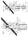
- zeigt als Ausführungsbeispiel der Erfindung eine Abgasanlage in Form eines doppelwandigen Kaminaufsatzes für einen Kaminstumpf in der betriebsmäßig montierten Anordnung, wobei die Abgasanlage Komponenten aufweist, die unterm Dach eines Gebäudes angeordnet sind.
- Fig. 2
- zeigt eine dem Ausführungsbeispiel nach Fig. 1 ähnliche Abgasanlage, wobei die Abgasanlage in Fig. 2 jedoch nach unten hin mit weiteren Komponenten des Rohrbaukastensystems zu einem vollständigen doppelwandigen Kamin verlängert ist.
- Fig. 1
- shows as an embodiment of the invention, an exhaust system in the form of a double-walled chimney cap for a stump in the operationally assembled arrangement, the exhaust system having components which are arranged under the roof of a building.
- Fig. 2
- shows an exhaust system similar to the embodiment of FIG. 1, but the exhaust system in FIG. 2 is extended downwards with other components of the modular pipe system to a complete double-walled chimney.
In Fig. 1 ist die Abgasanlage 2 als Kaminaufsatz oder Verlängerungsabschnitt eines bis unter das Dach 4 eines Gebäudes verkürzten Schornsteins 6 ausgebildet. Die Abgasanlage 2 ist aus drei doppelwandigen Rohrkomponenten 8a, 8b, 8c gebildet, welche Komponenten eines Baukastensystems für Kaminrohre sind. Die Komponenten 8a, 8b, 8c weisen jeweils einen Innenrohrabschnitt 10a, 10b, 10c und einen jeweiligen Außenrohrabschnitt 12a, 12b, 12c auf. Die Innenrohrabschnitte 10a, 10b, 10c sind durch Steckverbindungen aneinander angeschlossen und bilden so ein Abgas führendes erstes Rohr 10. In entsprechender Weise sind auch die Außenrohrabschnitte 12a, 12b, 12c durch Steckverbindungen aneinander angeschlossen und bilden ein zweites Rohr 12, welches das erste Rohr 10 konzentrisch umgibt. Ein ringförmiger Zwischenraum 14 zwischen dem ersten Rohr 10 und dem zweiten Rohr 12 dient als Kanal für eine Luftströmung nach oben zur Ausgangsseite 16 des Kaminaufsatzes 2, wobei die Luftströmung das zweite Rohr 12 an dessen endseitiger Öffnung 18 verlässt und dabei den Randbereich der Abgasaustrittsöffnung 20 des ersten Rohres streift (vgl. die Pfeile 19).In Fig. 1, the
In Fig. 1 ist zu erkennen, dass die unterste Komponente 8a des Kaminaufsatzes 2 mit einem unteren Einsteckende 22 des Rohrabschnittes 8a in das Abgasrohr 24 des Schornsteinstumpfes 6 eingesteckt ist. Diese Steckverbindung ist nach außen hin abgedichtet ausgeführt, so dass das in dem Abgasrohr 24 aufsteigende Abgas durch das erste Rohr 10 des Kaminaufsatzes 2 hindurch nach oben abgeleitet und an der Abgasaustrittsöffnung 20 ausgebracht wird. Der Au ßenrohrabschnitt 12a der Komponente 8a weist einen Luftzuführungsanschluss 26 in Form eines Stutzens auf, welcher schräg zur Kaminachse 28 außen an dem zweiten Rohr 12 angeordnet ist und darin einmündet. Die Neigung des Stutzens 26 wird so gewählt, dass die durch ihn eingeblasene Luft eine Strömungskomponente nach oben hat. Als Luftstromerzeuger dient ein Gebläse 30, welches unmittelbar an dem Stutzen 26 angebracht ist. In anderen Einbausituationen kann vorgesehen sein, dass das Gebläse 30 z.B. über einem flexiblem Luftschlauch an dem Stutzen 26 angeschlossen ist. Der ringförmige Zwischenraum 14 ist an seinem unteren axialen Ende im Wesentlichen verschlossen, so dass die von dem Gebläse 30 durch den Stutzen 26 in den ringförmigen Zwischenraum 14 eingeblasene Umgebungsluft nach oben entweichen kann. Die schnelle Luftströmung an der Gasaustrittsöffnung 20 des ersten Rohres 10 verursacht entsprechend dem Injektor-Prinzip einen Sog zum verbesserten Ausbringen von Abgas aus dem Abgasrohr 10.In Fig. 1 it can be seen that the
In der Anordnung gemäß Fig. 1 sind die Komponenten 8a und 8b prinzipiell gegeneinander austauschbar, so dass im Falle eines solchen Austausches der Luftzuführstutzen 26 weiter oben positioniert würde. Das daran angeschlossene Gehäuse 30 wäre auch dann noch geschützt unter dem Dach 4 untergebracht. Der Strömungsweg der Luft in dem Zwischenraum 14 wäre dann noch kürzer.In the arrangement according to FIG. 1, the
Der das Dach 4 durchsetzende Bereich des Kaminaufsatzes 2 ist optisch unauffällig und dezent. Gemäß einer Variante des Kaminaufsatzes 2 nach Fig. 1 kann ein mit Strichpunktlinien angedeutetes Abschlusselement 32 auf das Rohrelement 12c aufgesteckt sein. Das Abschlusselement 32 stellt dann eine axiale Verlängerung des zweiten Rohres 12 dar, wobei diese axiale Verlängerung im Beispielsfall auch eine Verengung des zweiten Rohres an dessen endseitiger Öffnung bedeutet. Die Abgasaustrittsöffnung 20 befindet sich in diesem Falle axial und radial innerhalb des zweiten Rohres 12.The area of the
In Fig. 2 ist das vorstehend unter Bezugnahme auf Fig. 1 erläuterte Ausführungsbeispiel nicht auf einem Kaminstumpf konventioneller Bauart aufgesetzt, sondern bildet den oberen Bereich eines insgesamt aus doppelwandigen Rohrkomponenten gebildeten Kamins, wobei die vorzugsweise aus Edelstahl bestehenden Rohrkomponenten 8a, 8b, 8c, 8d... aus dem betreffenden Baukastensystem stammen. Unterhalb der Komponente 8a mit dem Lufteinlassstutzen 26 weisen die Rohrkomponenten 8d... eine Wärmeisolierung 34 in dem Zwischenraum 14 zwischen Innenrohr 10 und Außenrohr 12 auf.In FIG. 2, the exemplary embodiment explained above with reference to FIG. 1 is not placed on a chimney stump of conventional design, but instead forms the upper region of a chimney made entirely of double-walled pipe components, the
Abgasanlagen mit solchen Komponenten 8d... mit Zwischenraumisolierung 14 zwischen Innenrohr und Außenrohr, und zwar im Wesentlichen über die gesamte Kaminlänge, sind vielfach im Einsatz. Fig. 2 legt unmittelbar nahe, dass ein solcher konventioneller Kamin mit wenigen einfachen Schritten in erfindungsgemäßer Weise umgestaltet werden kann, nämlich dadurch, dass man eine der betreffenden Komponenten austauscht gegen eine Komponente 8a mit einem Luftzuführungsanschluss 26 austauscht und die dann ggf. auf das Element 8a aufzusetzenden Komponenten (vgl. 8b und 8c in Fig. 2) von etwaigem Isoliermaterial befreit, um den Ringkanal nach oben hin für die einzublasende Luft zu präparieren.Exhaust systems with
Der Luftzuführbetrieb, also der Betrieb des Gebläses 30 in Fig. 1 bzw. in Fig. 2 kann z.B. gesteuert in Abhängigkeit von sensorisch überwachten Bedingungen erfolgen, die den Kaminzug beeinflussen, also etwa Witterungsbedingungen, Abgastemperaturbedingungen, Druckschwankungen usw. Sofern ein für eine zuverlässige Ausbringung des Abgases hinreichender Kaminzug vorliegt, kann das Gebläse 30 passiv geschaltet werden.The air supply operation, i.e. the operation of the
Es kann auch Anwendungsfälle geben, in denen eine Abgasanlage nach der Erfindung mit Dauerbetrieb des Gebläses vorzusehen ist. Dies können z.B. Fälle sein, in denen bisher der Einsatz von Ventilatoren im Gasableitungsweg erforderlich bzw. vorgeschrieben war. Aufgrund des mit der vorliegenden Erfindung erzielten Gasabsaugungseffektes kann auf solche Ventilatoren ggf. verzichtet werden.There may also be applications in which an exhaust system according to the invention is to be provided with continuous operation of the fan. This can e.g. Cases in which the use of fans in the gas discharge path was previously required or prescribed. Because of the gas extraction effect achieved with the present invention, such fans may be dispensed with.
Claims (19)
Hilfsgasstromerzeugungseinrichtung (30) ein Gebläse zum Ansaugen von Umgebungsluft umfasst.Exhaust system according to one of the preceding claims, characterized in that the
Auxiliary gas flow generating device (30) comprises a blower for sucking in ambient air.
Applications Claiming Priority (2)
| Application Number | Priority Date | Filing Date | Title |
|---|---|---|---|
| DE20216502U | 2002-10-25 | ||
| DE20216502U DE20216502U1 (en) | 2002-10-25 | 2002-10-25 | Gas extraction device for a gas discharge system |
Publications (2)
| Publication Number | Publication Date |
|---|---|
| EP1413828A2 true EP1413828A2 (en) | 2004-04-28 |
| EP1413828A3 EP1413828A3 (en) | 2008-06-11 |
Family
ID=31969859
Family Applications (1)
| Application Number | Title | Priority Date | Filing Date |
|---|---|---|---|
| EP03024365A Withdrawn EP1413828A3 (en) | 2002-10-25 | 2003-10-24 | Exhaust system and method of operating a double-walled chimney pipe |
Country Status (2)
| Country | Link |
|---|---|
| EP (1) | EP1413828A3 (en) |
| DE (1) | DE20216502U1 (en) |
Cited By (1)
| Publication number | Priority date | Publication date | Assignee | Title |
|---|---|---|---|---|
| FR2976329A1 (en) * | 2011-06-07 | 2012-12-14 | Cmi Thermline Services | AERODYNAMIC DEVICE FOR REGULATING TEMPERATURE AND PRESSURE IN A FLUID CIRCULATION CIRCUIT |
Families Citing this family (3)
| Publication number | Priority date | Publication date | Assignee | Title |
|---|---|---|---|---|
| DE102007039984B4 (en) * | 2007-08-23 | 2015-11-12 | Truma Gerätetechnik GmbH & Co. KG | Exhaust device for a combustion device and a heating system in a vehicle |
| DE202007017770U1 (en) | 2007-12-20 | 2009-04-23 | Kutzner + Weber Gmbh | Gas discharge arrangement |
| CN106338081B (en) * | 2016-11-03 | 2018-10-19 | 中国公路车辆机械有限公司 | A kind of double micro- adjustable high temperature flue gas ejectors of no receiving chamber |
Citations (2)
| Publication number | Priority date | Publication date | Assignee | Title |
|---|---|---|---|---|
| DE2230471A1 (en) | 1972-06-14 | 1974-11-14 | Sulzer Ag | PROCEDURE FOR REDUCING IMMISSIONS OF A CHIMNEY AND DEVICE FOR CARRYING OUT THE PROCEDURE |
| EP0798513B1 (en) | 1996-03-23 | 2002-07-17 | Karl Schräder Nachfolger Inh. Karl-Heinz Schräder | Double walled pipe element for building chimneys |
Family Cites Families (5)
| Publication number | Priority date | Publication date | Assignee | Title |
|---|---|---|---|---|
| BE381135A (en) * | ||||
| GB190923791A (en) * | 1909-10-18 | 1910-09-15 | John Landells | Improvements relating to the Production of Induced Draught in Chimneys and the like. |
| US3586441A (en) * | 1967-07-12 | 1971-06-22 | Instrumentation Labor Inc | Atomic absorption spectroanalysis system |
| DE2817450A1 (en) * | 1978-04-21 | 1979-08-16 | Wolfgang Graffius | Centrifugal waste gas blower for chimney - has blower casing formed integrally with concrete block sized to suit chimney structure |
| GB8508275D0 (en) * | 1985-03-29 | 1985-05-09 | Kershaw C J | Chimney flues |
-
2002
- 2002-10-25 DE DE20216502U patent/DE20216502U1/en not_active Expired - Lifetime
-
2003
- 2003-10-24 EP EP03024365A patent/EP1413828A3/en not_active Withdrawn
Patent Citations (2)
| Publication number | Priority date | Publication date | Assignee | Title |
|---|---|---|---|---|
| DE2230471A1 (en) | 1972-06-14 | 1974-11-14 | Sulzer Ag | PROCEDURE FOR REDUCING IMMISSIONS OF A CHIMNEY AND DEVICE FOR CARRYING OUT THE PROCEDURE |
| EP0798513B1 (en) | 1996-03-23 | 2002-07-17 | Karl Schräder Nachfolger Inh. Karl-Heinz Schräder | Double walled pipe element for building chimneys |
Cited By (3)
| Publication number | Priority date | Publication date | Assignee | Title |
|---|---|---|---|---|
| FR2976329A1 (en) * | 2011-06-07 | 2012-12-14 | Cmi Thermline Services | AERODYNAMIC DEVICE FOR REGULATING TEMPERATURE AND PRESSURE IN A FLUID CIRCULATION CIRCUIT |
| EP2532960A3 (en) * | 2011-06-07 | 2013-10-02 | Sa Cockerill Maintenance Et Ingenierie | Aerodynamic device for regulating the temperature and pressure in a fluid circulation circuit |
| BE1020814A5 (en) * | 2011-06-07 | 2014-05-06 | Cockerill Maintenance & Ingenierie Sa | AERODYNAMIC DEVICE FOR REGULATING TEMPERATURE AND PRESSURE IN A FLUID CIRCULATION CIRCUIT. |
Also Published As
| Publication number | Publication date |
|---|---|
| EP1413828A3 (en) | 2008-06-11 |
| DE20216502U1 (en) | 2004-02-26 |
Similar Documents
| Publication | Publication Date | Title |
|---|---|---|
| EP2336503A2 (en) | Arrangement for the discharge of ventilation air separated from the lubricating oil de-aeration system of a gas-turbine engine | |
| EP1413828A2 (en) | Exhaust system and method of operating a double-walled chimney pipe | |
| WO2008113664A2 (en) | Extractor hood | |
| EP2500663A1 (en) | Smoke protection assembly | |
| DE202010002826U1 (en) | Apparatus for washing flue gas | |
| DE3643797A1 (en) | ATMOSPHERIC GAS HEATER WITH EXTERNAL EXHAUST GAS RECIRCULATION FOR NO (DOWN ARROW) X (DOWN ARROW) REDUCTION | |
| DE3121467C1 (en) | Fan/ventilator cooling tower having at least one forcing fan | |
| EP2175209B1 (en) | Calorific value heater | |
| DE202006011229U1 (en) | Oil tank with ventilation system | |
| DE10255172A1 (en) | Small-scale modular ventilation system for a single room has a basic unit with control unit, condensed water trap and an ambient air inlet/outlet pipe | |
| DE2607712A1 (en) | Fireplace waste air mixing hood - has internal shallow funnel within truncated conical hood for mixing | |
| DE19950817A1 (en) | Extractor hood | |
| EP2539047A1 (en) | Pipe and condensate boundary film collection and drainage device for installation in said pipe | |
| EP0330096B1 (en) | Device for the purification of gas | |
| DE19743591A1 (en) | Engine inflow stabilizing process for running at rest | |
| EP2322870A1 (en) | Condensing boiler | |
| EP1959206B1 (en) | Floor device and method for venting , heating or cooling a room | |
| DE102019107183B4 (en) | Fan arrangement and dedusting system | |
| DE4219113C2 (en) | Device for influencing the exhaust gases of external wall heating devices operated with fossil fuels and independent of the ambient air | |
| DE102010009347A1 (en) | Device for washing flue gas e.g. sulfur di-oxide, from incinerator for incineration of timber for reducing pollutant emissions in exhaust gas stream in industry, has turbulence plates provided for turbulence of wash water and flue gas | |
| WO2006037642A1 (en) | Device for protecting non-smokers | |
| EP3892919A1 (en) | Flow guidance device for guiding at least one fluid flow in the region of a conveying device of a heating device for a building | |
| DE19904428C2 (en) | Mechanical smoke and heat exhaust system | |
| DE202022106948U1 (en) | Airflow Filter Module | |
| DE3507245A1 (en) | Auxiliary device for ventilation installations and chimneys |
Legal Events
| Date | Code | Title | Description |
|---|---|---|---|
| PUAI | Public reference made under article 153(3) epc to a published international application that has entered the european phase |
Free format text: ORIGINAL CODE: 0009012 |
|
| AK | Designated contracting states |
Kind code of ref document: A2 Designated state(s): AT BE BG CH CY CZ DE DK EE ES FI FR GB GR HU IE IT LI LU MC NL PT RO SE SI SK TR |
|
| AX | Request for extension of the european patent |
Extension state: AL LT LV MK |
|
| PUAL | Search report despatched |
Free format text: ORIGINAL CODE: 0009013 |
|
| AK | Designated contracting states |
Kind code of ref document: A3 Designated state(s): AT BE BG CH CY CZ DE DK EE ES FI FR GB GR HU IE IT LI LU MC NL PT RO SE SI SK TR |
|
| AX | Request for extension of the european patent |
Extension state: AL LT LV MK |
|
| 17P | Request for examination filed |
Effective date: 20081117 |
|
| AKX | Designation fees paid |
Designated state(s): AT BE BG CH CY CZ DE DK EE ES FI FR GB GR HU IE IT LI LU MC NL PT RO SE SI SK TR |
|
| 17Q | First examination report despatched |
Effective date: 20110329 |
|
| STAA | Information on the status of an ep patent application or granted ep patent |
Free format text: STATUS: THE APPLICATION IS DEEMED TO BE WITHDRAWN |
|
| 18D | Application deemed to be withdrawn |
Effective date: 20120503 |