EP1413766B1 - Anordnung eines Verdichterlaufrades - Google Patents
Anordnung eines Verdichterlaufrades Download PDFInfo
- Publication number
- EP1413766B1 EP1413766B1 EP03256588A EP03256588A EP1413766B1 EP 1413766 B1 EP1413766 B1 EP 1413766B1 EP 03256588 A EP03256588 A EP 03256588A EP 03256588 A EP03256588 A EP 03256588A EP 1413766 B1 EP1413766 B1 EP 1413766B1
- Authority
- EP
- European Patent Office
- Prior art keywords
- shaft
- wheel
- compressor wheel
- compressor
- keying formations
- Prior art date
- Legal status (The legal status is an assumption and is not a legal conclusion. Google has not performed a legal analysis and makes no representation as to the accuracy of the status listed.)
- Expired - Lifetime
Links
- 230000015572 biosynthetic process Effects 0.000 claims description 18
- 238000005755 formation reaction Methods 0.000 claims description 18
- 230000000712 assembly Effects 0.000 description 2
- 238000000429 assembly Methods 0.000 description 2
- 238000002485 combustion reaction Methods 0.000 description 2
- 238000012986 modification Methods 0.000 description 2
- 230000004048 modification Effects 0.000 description 2
- 229910000838 Al alloy Inorganic materials 0.000 description 1
- RTAQQCXQSZGOHL-UHFFFAOYSA-N Titanium Chemical compound [Ti] RTAQQCXQSZGOHL-UHFFFAOYSA-N 0.000 description 1
- 238000010276 construction Methods 0.000 description 1
- 238000002955 isolation Methods 0.000 description 1
- 239000000463 material Substances 0.000 description 1
- 238000000034 method Methods 0.000 description 1
- 239000013500 performance material Substances 0.000 description 1
- 230000000717 retained effect Effects 0.000 description 1
- 239000013589 supplement Substances 0.000 description 1
- 239000010936 titanium Substances 0.000 description 1
- 229910052719 titanium Inorganic materials 0.000 description 1
- 230000001052 transient effect Effects 0.000 description 1
Images

Classifications
-
- F—MECHANICAL ENGINEERING; LIGHTING; HEATING; WEAPONS; BLASTING
- F02—COMBUSTION ENGINES; HOT-GAS OR COMBUSTION-PRODUCT ENGINE PLANTS
- F02B—INTERNAL-COMBUSTION PISTON ENGINES; COMBUSTION ENGINES IN GENERAL
- F02B39/00—Component parts, details, or accessories relating to, driven charging or scavenging pumps, not provided for in groups F02B33/00 - F02B37/00
-
- F—MECHANICAL ENGINEERING; LIGHTING; HEATING; WEAPONS; BLASTING
- F04—POSITIVE - DISPLACEMENT MACHINES FOR LIQUIDS; PUMPS FOR LIQUIDS OR ELASTIC FLUIDS
- F04D—NON-POSITIVE-DISPLACEMENT PUMPS
- F04D29/00—Details, component parts, or accessories
- F04D29/26—Rotors specially for elastic fluids
- F04D29/266—Rotors specially for elastic fluids mounting compressor rotors on shafts
Definitions
- This invention relates to the assembly of a compressor wheel to a rotating shaft.
- the invention relates to the compressor wheel assembly of a turbocharger.
- Turbochargers are well known devices for supplying air to the intake of an internal combustion engine at pressures above atmospheric (boost pressures).
- a conventional turbocharger essentially comprises an exhaust gas driven turbine wheel mounted on a rotatable shaft within a turbine housing. Rotation of the turbine wheel rotates a compressor wheel mounted on the other end of the shaft within a compressor housing. The compressor wheel delivers compressed air to the intake manifold of the engine, thereby increasing engine power.
- the shaft is supported on journal and thrust bearings located within a central bearing housing connected between the turbine and compressor wheel housings.
- a conventional compressor wheel comprises an array of blades extending from a central hub provided with a bore for receiving one end of the turbocharger shaft.
- the compressor wheel is secured to the shaft by a nut which threads onto the end of the shaft where it extends through the wheel bore, and bears against the nose end of the wheel to clamp the wheel against a shaft shoulder (or other radially extending abutment that rotates with the shaft). It is important that the clamping force is sufficiently great to prevent slippage of the wheel on the shaft which could throw the wheel out of balance. An unbalanced wheel will at the very least experience increased vibration, which could shorten the working life of the wheel, and at worst could suffer catastrophic failure.
- US patent number 3,019,039 discloses a method of mounting a compressor wheel to a shaft in which the compressor wheel is mechanically coupled to the shaft.
- the compressor wheel is mounted on a shaft between a shoulder on the shaft and a nut threaded on to the end of the shaft.
- a disc is mounted on the shaft between the hub of the compressor wheel and the shaft shoulder and is retained in position on the shaft by pins extending radially through the disc and in to the shaft.
- Radial keys are disposed on one face of the disc and engaging in slots formed on the rear face of the hub of the compressor wheel to key the compressor wheel to the disc, which in turn is keyed to the shaft.
- Another known arrangement for mounting a compressor wheel to a shaft is disclosed in US patent 2,577,134.
- a compressor wheel is held on a shaft between a nut and a shoulder on the shaft.
- the nut bears against a nose piece which is keyed to the shaft so as to rotate with the shaft.
- the nose piece is also keyed to the compressor by radially extending splines provided on one of the compressor wheel and nose piece which engage with slots provided on the other of the compressor wheel and nose piece. The nose piece thus mechanically couples the compressor wheel to the shaft for rotation therewith.
- a compressor wheel assembly comprising:
- the driving force for the compressor wheel is provided by a positive interlocking engagement between the shaft and the wheel.
- the clamping force provided by the nut is only required to prevent axial movement of the wheel along the shaft. However, if desirable the clamping force could be sufficient to assist the keying engagement ensuring the driving load.
- FIG. 1 illustrates the basic components of a conventional centripetal type turbocharger.
- the turbocharger comprises a turbine 1 joined to a compressor 2 via a central bearing housing 3.
- the turbine 1 comprises a turbine housing 4 which houses a turbine wheel 5.
- the compressor 2 comprises a compressor housing 6 which houses a compressor wheel 7.
- the turbine wheel 5 and compressor wheel 7 are mounted on opposite ends of a common shaft 8 which is supported on bearing assemblies 9 within the bearing housing 3.
- the turbine housing 4 is provided with an exhaust gas inlet 10 and an exhaust gas outlet 11.
- the inlet 10 directs incoming exhaust gas to an annular inlet chamber 12 surrounding the turbine wheel 5.
- the exhaust gas flows through the turbine and into the outlet 11 via a circular outlet opening which is co-axial with the turbine wheel 5.
- Rotation of the turbine wheel 5 rotates the compressor wheel 7 which draws in air through axial inlet 13 and delivers compressed air to the engine intake via an annular outlet volute 14.
- the compressor wheel comprises a plurality of blades 15 extending from a central hub 16 which is provided with a through bore to receive one end of the shaft 8.
- the shaft 8 extends slightly from the nose of the compressor wheel 7 and is threaded to receive a nut 17 which bears against the compressor wheel nose to clamp the compressor wheel 7 against a thrust bearing and oil seal assembly 18.
- Details of the thrust bearing/oil seal assembly may vary and are not important to understanding of the compressor wheel mounting arrangement. Essentially, the compressor wheel 7 is prevented from slipping on the shaft 8 by the clamping force applied by the nut 17.
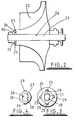
- FIGS 2 and 3 illustrate one example of a compressor wheel assembly in accordance with the present invention.
- the turbocharger shaft 20 is modified by the provision of two opposing flats 21 provided at the threaded end of the shaft 20.
- the flats 21 may for instance simply be machined into the end of the shaft 20.
- the nose portion of the compressor wheel 22 is countersunk to provide a recess 23 of larger diameter than the compressor wheel through bore 24 which receives the shaft 20.
- Four circumferentially equi-spaced slots or recesses 25 are provided in the nose of the compressor wheel 22 extending radially from the countersunk recess 23.
- a drive washer 26 (shown in isolation figure 4), sits around the shaft 20 within the recess 23.
- the drive washer 26 has a non-circular central aperture 27 provided with opposing flats 28 which engage the flats 21 provided on the shaft 20.
- Two diametrically opposed lugs 29 extend radially from the circular outer circumference of the drive washer 26 and engage within diametrically opposed slots 25 provided in the recessed nose portion of the compressor wheel 22.
- the drive washer 26 is held in place by a flanged nut 30 threaded onto the end of the shaft 20.
- the compressor wheel 22 is thus keyed to the shaft 20 via the drive washer 26 which acts as a keying member.
- the shaft 20 and wheel 22 are thus interlocked and must rotate together. It is not therefore possible for the wheel 22 to slip as the shaft 20 rotates. This removes (or at least reduces) the reliance on the clamping force provided by the nut 29, which need only be sufficient to maintain the drive washer 26 in place and prevent axial movement of the wheel 22 along the shaft 20. However, a clamping force provided by the nut 29 may be relied upon to supplement the keying action of the drive washer 26 and share the drive load.
- the number of flats provided on the end of the shaft may vary i.e. there may be only one or more than two.
- the number of lugs provided on the drive washer and/or slots provided in the nose of the compressor wheel may be varied. It is preferable to have a plurality of at least one or the other to provide a number of alternative angular mounting positions for the compressor wheel to aid in balancing of the compressor wheel assembly. It is also preferable to have a plurality of keying engagements between the compressor wheel and drive washer/turbocharger shaft to distribute the drive load.
- the keying formations provided on the drive washer, and on the shaft and wheel may take a different configuration from those illustrated.
- the compressor wheel could be provided with radially inward projections and the drive washer could be provided with recesses in its external surface to receive those projections.
- the outer circumference of the drive washer could be provided with flats to engage appropriate formation (such as flat portions) defined within the compressor wheel bore.
- other forms of keying engagement may be provided between the drive washer and the shaft, such as projections provided on the drive washer and recesses provided on the shaft.
- Other possible alternatives will be readily apparent to the appropriately skilled person.
- keying member may be used in place of the drive washer 26.
- a plurality of keying members may be provided to interengage between respective formations provided on the shaft and compressor wheel.
- both the shaft and compressor wheel could be provided with slots or the like which register with one another, respective keying members extending between the aligned slots/apertures to prevent them rotating out of alignment.
- such arrangements are likely to be more complex in construction and assembly than the advantageously simple drive washer form of keying member.
- the invention can be implemented by providing direct keying between the compressor wheel and turbocharger shaft without the provision of a separate keying member.
- the internal bore of the wheel, and the shaft may be provided with directly interengaging keying formations.
- the nose portion of the wheel may be provided with protuberances which extend radially inwards and engage with flats, or recesses, machined into the end of the shaft.
- Such arrangements may be more applicable to compressor wheels which have a cast central bore rather than compressor wheels in which the bore is drilled.
- the present invention is not limited in application to any particular form of compressor wheel, or inboard assembly of bearings etc.
- the present invention is not limited in application to turbocharger compressor wheels but can be applied to compressor wheels in other applications, including, but not limited to, other forms of internal combustion engine supercharger (such as a belt driven compressor wheel).
Landscapes
- Engineering & Computer Science (AREA)
- Mechanical Engineering (AREA)
- General Engineering & Computer Science (AREA)
- Chemical & Material Sciences (AREA)
- Combustion & Propulsion (AREA)
- Structures Of Non-Positive Displacement Pumps (AREA)
- Supercharger (AREA)
- Applications Or Details Of Rotary Compressors (AREA)
- Compressor (AREA)
Claims (6)
- Verdichterlaufrad-Baugruppe, die Folgendes umfasst:ein Verdichterlaufrad (22), angebracht an einer rotierenden Welle (20), wobei sich die Welle (20) durch eine längs der Rotationsachse des Rades (22) bereitgestellte Bohrung (24) erstreckt,eine Mutter (30), die auf das eine Ende der Welle (20) geschraubt ist und mittelbar an einem Ansatzabschnitt des Rades (22) anliegt, um das Rad (22) gegen ein Widerlager zu klemmen und eine Axialbewegung des Rades (22) längs der Welle (20) zu verhindern,Verkeilungsformationen (25, 21), bereitgestellt an dem Rad (22) bzw. der Welle (20),eine Antriebsscheibe (26), angeordnet um die Welle (20) zwischen der Mutter (30) und dem Rad (22), wobei die Antriebsscheibe (26) eine innere Öffnung (27) zum Aufnehmen der Welle (20) und innere und äußere Verkeilungsformationen (28, 29), welche die Wellen- bzw. die Radverkeilungsformationen (21, 25) in Eingriff nehmen, hat,wobei die Radverkeilungsformationen Aussparungen (25), die sich in Radialrichtung in das Rad (22) erstrecken, umfassen und die äußeren Verkeilungsformationen der Antriebsscheibe radiale Vorsprünge (29), welche die Aussparungen (25) in Eingriff nehmen, umfassen.
- Verdichterlaufrad-Baugruppe nach Anspruch 1, wobei die Wellenverkeilungsformationen einen oder mehrere flache Abschnitte (21), bereitgestellt im Umfang der Welle (20), umfassen und die inneren Verkeilungsformationen (28) der Antriebsscheibe (26) lineare Abschnitte (28) der Scheibenöffnung umfassen.
- Verdichterlaufrad-Baugruppe nach einem der vorhergehenden Ansprüche, versehen mit mehreren Verkeilungsformationen (25, 21) an dem Verdichterlaufrad (22) und/oder der Welle (20), die ein Schalten der relativen Winkelposition des Rades (22) an der Welle (20) erlauben, um das Radauswuchten zu unterstützen.
- Verdichterlaufrad-Baugruppe nach einem der vorhergehenden Ansprüche, wobei die Antriebsscheibe (26) mit mehreren inneren und/oder äußeren Verkeilungsformationen (28, 29) versehen ist, um ein Schalten der Drehposition des Rades (22) im Verhältnis zu der Welle (20) zu ermöglichen, um das Radauswuchten zu unterstützen.
- Verdichterlaufrad-Baugruppe nach einem der vorhergehenden Ansprüche, wobei der Ansatzabschnitt des Rades (22) versenkt ist, um die Antriebsscheibe (26) aufzunehmen.
- Turbolader, der eine Verdichterlaufrad-Baugruppe nach einem der vorhergehenden Ansprüche umfasst.
Applications Claiming Priority (2)
| Application Number | Priority Date | Filing Date | Title |
|---|---|---|---|
| GBGB0224721.1A GB0224721D0 (en) | 2002-10-24 | 2002-10-24 | Compressor wheel assembly |
| GB0224721 | 2002-10-24 |
Publications (3)
| Publication Number | Publication Date |
|---|---|
| EP1413766A2 EP1413766A2 (de) | 2004-04-28 |
| EP1413766A3 EP1413766A3 (de) | 2005-04-13 |
| EP1413766B1 true EP1413766B1 (de) | 2007-02-14 |
Family
ID=9946474
Family Applications (1)
| Application Number | Title | Priority Date | Filing Date |
|---|---|---|---|
| EP03256588A Expired - Lifetime EP1413766B1 (de) | 2002-10-24 | 2003-10-20 | Anordnung eines Verdichterlaufrades |
Country Status (7)
| Country | Link |
|---|---|
| US (1) | US7008191B2 (de) |
| EP (1) | EP1413766B1 (de) |
| JP (1) | JP2004144095A (de) |
| KR (1) | KR20040036656A (de) |
| CN (1) | CN100520008C (de) |
| DE (1) | DE60311725T2 (de) |
| GB (1) | GB0224721D0 (de) |
Families Citing this family (30)
| Publication number | Priority date | Publication date | Assignee | Title |
|---|---|---|---|---|
| GB0224723D0 (en) * | 2002-10-24 | 2002-12-04 | Holset Engineering Co | Compressor wheel assembly |
| GB0224727D0 (en) * | 2002-10-24 | 2002-12-04 | Holset Engineering Co | Compressor wheel assembly |
| GB0224726D0 (en) * | 2002-10-24 | 2002-12-04 | Holset Engineering Co | Compressor wheel assembly |
| EP1803941A1 (de) * | 2004-10-19 | 2007-07-04 | Komatsu Ltd | Turbomaschine, für die turbomaschine verwendetes verdichterlaufrad und verfahren zur herstellung der turbomaschine |
| JP4053563B2 (ja) * | 2005-12-01 | 2008-02-27 | ファナック株式会社 | 流体機械 |
| GB2435675B (en) * | 2006-03-02 | 2011-02-09 | Boc Group Plc | Rotor assembly |
| DE102008043403B4 (de) * | 2008-11-03 | 2019-06-27 | Robert Bosch Gmbh | Lüfter, Verfahren zur Montage eines Lüfterrades und Vorrichtung |
| WO2010111133A2 (en) * | 2009-03-26 | 2010-09-30 | Borgwarner Inc. | Reduction of turbocharger core unbalance with balance washer |
| DE102009060056A1 (de) | 2009-12-22 | 2011-06-30 | BorgWarner Inc., Mich. | Wellenverband eines Abgasturboladers |
| US20110206521A1 (en) * | 2010-02-23 | 2011-08-25 | Alex Horng | Rotating Part Assembly for Motor |
| JP2011196327A (ja) * | 2010-03-23 | 2011-10-06 | Ihi Corp | ターボ圧縮機、ターボ冷凍機及びターボ圧縮機の製造方法 |
| JP5406812B2 (ja) * | 2010-09-30 | 2014-02-05 | 株式会社神戸製鋼所 | 遠心式流体機械用ロータ |
| US10465698B2 (en) | 2011-11-08 | 2019-11-05 | Garrett Transportation I Inc. | Compressor wheel shaft with recessed portion |
| JP5967966B2 (ja) * | 2012-02-13 | 2016-08-10 | 三菱重工コンプレッサ株式会社 | インペラ及びこれを備えた回転機械 |
| DE102012207271A1 (de) * | 2012-05-02 | 2013-11-07 | Robert Bosch Gmbh | Verfahren zum Verbinden einer Welle mit einem Rotationsbauteil und nach diesem Verfahren hergestellte Turboladerwelle |
| CN102691575B (zh) * | 2012-06-11 | 2014-07-09 | 湖南航翔燃气轮机有限公司 | 传动装置及具有该传动装置的燃气轮机 |
| JP6159798B2 (ja) * | 2012-06-25 | 2017-07-05 | ボーグワーナー インコーポレーテッド | 排気ガスターボチャージャ |
| KR101336331B1 (ko) * | 2012-08-06 | 2013-12-06 | 자동차부품연구원 | 터보 차져의 로터 조립체 |
| KR102032389B1 (ko) * | 2012-08-07 | 2019-10-15 | 보르그워너 인코퍼레이티드 | 밸런스 교정 및 포지티브 파일럿팅을 이용하는 압축기 휠 |
| WO2014062208A1 (en) * | 2012-10-02 | 2014-04-24 | Borgwarner Inc. | Reduction of turbocharger core unbalance with balance washer |
| DE102012218692B4 (de) | 2012-10-15 | 2014-11-20 | Continental Automotive Gmbh | Abgasturboladerwelle mit dieser verbundenem Laufrad |
| WO2014088824A1 (en) * | 2012-12-06 | 2014-06-12 | Borgwarner Inc. | Exhaust-gas turbocharger |
| JP6159418B2 (ja) | 2013-12-11 | 2017-07-05 | 三菱重工業株式会社 | 回転体及び該回転体の製造方法 |
| CN107208658B (zh) * | 2015-02-18 | 2019-07-05 | 株式会社Ihi | 离心压缩机及增压器 |
| US10975878B2 (en) | 2016-03-03 | 2021-04-13 | Ihi Corporation | Rotary machine |
| US10060067B2 (en) | 2016-05-10 | 2018-08-28 | Haier Us Appliance Solutions, Inc. | Determining out of balance conditions of a washing machine |
| US10876547B2 (en) * | 2016-09-07 | 2020-12-29 | Garrett Transportation I Inc. | Compressor wheel and shaft assembly |
| CN110998102B (zh) * | 2017-07-31 | 2021-04-02 | 三菱电机株式会社 | 风扇和具备风扇的空调装置的室内机 |
| US20190113046A1 (en) * | 2017-10-16 | 2019-04-18 | Borgwarner Inc. | Polymer Compressor Wheel with Co-Molded Bore Insert |
| US11585348B2 (en) * | 2019-03-14 | 2023-02-21 | Mitsubishi Heavy Industries Engine & Turbocharger, Ltd. | Compressor wheel device and supercharger |
Family Cites Families (19)
| Publication number | Priority date | Publication date | Assignee | Title |
|---|---|---|---|---|
| US2577134A (en) * | 1949-02-19 | 1951-12-04 | Elliott Co | Radial spline impeller drive for turbochargers |
| US3019039A (en) * | 1956-04-09 | 1962-01-30 | Fairchild Stratos Corp | Means for mounting a body on a rotating shaft |
| US3321221A (en) * | 1965-01-13 | 1967-05-23 | Rotron Mfg Co | Fastener |
| JPS4815164B1 (de) * | 1968-08-20 | 1973-05-12 | ||
| DE2527498A1 (de) * | 1975-06-20 | 1976-12-30 | Daimler Benz Ag | Radialturbinenrad fuer eine gasturbine |
| DE2621201C3 (de) * | 1976-05-13 | 1979-09-27 | Maschinenfabrik Augsburg-Nuernberg Ag, 8900 Augsburg | Laufrad für eine Strömungsmaschine |
| US4353685A (en) * | 1978-06-19 | 1982-10-12 | Wrr Industries, Inc. | Turbocharger compressor rotor retainer |
| GB2030269B (en) | 1978-09-19 | 1983-04-27 | Rolls Royce | Shaft coupliner |
| KR830002159A (ko) * | 1979-03-21 | 1983-05-23 | 에이. 더블유. 프리쉬 | 고속 가스 압축기용 임펠러와 축 조립체 |
| US4417855A (en) * | 1981-06-08 | 1983-11-29 | Air Products And Chemicals, Inc. | Mounting assembly for high speed turbo discs |
| JPS5898629A (ja) | 1981-12-08 | 1983-06-11 | Toyota Motor Corp | タ−ボチヤ−ジヤの回転体の締結機構 |
| US4705463A (en) * | 1983-04-21 | 1987-11-10 | The Garrett Corporation | Compressor wheel assembly for turbochargers |
| US5193989A (en) * | 1991-07-19 | 1993-03-16 | Allied-Signal Inc. | Compressor wheel and shaft assembly for turbocharger |
| JP3777648B2 (ja) * | 1996-04-03 | 2006-05-24 | 石川島播磨重工業株式会社 | 羽根車の締結構造 |
| DE19736333C1 (de) * | 1997-08-21 | 1999-03-04 | Man B & W Diesel Ag | Befestigung eines Laufrades einer Strömungsmaschine an einer Welle |
| US6499958B2 (en) * | 1999-07-02 | 2002-12-31 | Ingersoll-Rand Company | Device and method for detachably connecting an impeller to a pinion shaft in a high speed fluid compressor |
| GB0224727D0 (en) * | 2002-10-24 | 2002-12-04 | Holset Engineering Co | Compressor wheel assembly |
| GB0224723D0 (en) * | 2002-10-24 | 2002-12-04 | Holset Engineering Co | Compressor wheel assembly |
| GB0224726D0 (en) * | 2002-10-24 | 2002-12-04 | Holset Engineering Co | Compressor wheel assembly |
-
2002
- 2002-10-24 GB GBGB0224721.1A patent/GB0224721D0/en not_active Ceased
-
2003
- 2003-10-20 EP EP03256588A patent/EP1413766B1/de not_active Expired - Lifetime
- 2003-10-20 DE DE60311725T patent/DE60311725T2/de not_active Expired - Lifetime
- 2003-10-22 US US10/691,388 patent/US7008191B2/en not_active Expired - Lifetime
- 2003-10-24 KR KR1020030074546A patent/KR20040036656A/ko not_active Application Discontinuation
- 2003-10-24 JP JP2003364666A patent/JP2004144095A/ja active Pending
- 2003-10-24 CN CNB2003101198365A patent/CN100520008C/zh not_active Expired - Fee Related
Also Published As
| Publication number | Publication date |
|---|---|
| US20040131469A1 (en) | 2004-07-08 |
| GB0224721D0 (en) | 2002-12-04 |
| EP1413766A2 (de) | 2004-04-28 |
| JP2004144095A (ja) | 2004-05-20 |
| DE60311725D1 (de) | 2007-03-29 |
| CN100520008C (zh) | 2009-07-29 |
| EP1413766A3 (de) | 2005-04-13 |
| US7008191B2 (en) | 2006-03-07 |
| CN1510259A (zh) | 2004-07-07 |
| DE60311725T2 (de) | 2007-11-22 |
| KR20040036656A (ko) | 2004-04-30 |
Similar Documents
| Publication | Publication Date | Title |
|---|---|---|
| EP1413766B1 (de) | Anordnung eines Verdichterlaufrades | |
| EP0522630B1 (de) | Schleuderradverriegelung in einer Antriebsanordnung | |
| EP1467062B1 (de) | Rotor eines Turboladers | |
| EP1614207B1 (de) | Elektromotorgehäuse für einen elektrisch unterstützten turbolader | |
| EP1273765B1 (de) | Zweiphasendichtung für einenTurbolader | |
| EP1805398B1 (de) | Turbolader mit druckring | |
| US5547350A (en) | Modular shaftless compressor | |
| JP4671177B2 (ja) | 電動過給機 | |
| JP4648347B2 (ja) | ハイブリッド排気タービン過給機 | |
| EP1413765B1 (de) | Anordnung eines Verdichterlaufrades | |
| US5193989A (en) | Compressor wheel and shaft assembly for turbocharger | |
| JPH11148492A (ja) | 高速回転型のターボ機械に用いられる圧縮機羽根車固定装置 | |
| CN101709667A (zh) | 涡轮机 | |
| EP0908629A1 (de) | Verdichter oder Turbine | |
| EP1197638A2 (de) | Lager für Turbolader | |
| US20050042105A1 (en) | Compressor of turbo machine and its compressor wheel | |
| US5536144A (en) | Turbocharger turbine wheel and shaft assembly | |
| EP1413767A2 (de) | Anordnung eines Verdichterlaufrades | |
| EP1413764A2 (de) | Anordnung eines Verdichterlaufrades | |
| CN217735581U (zh) | 一种多级叶轮转子结构及发电机组 | |
| EP4063617A1 (de) | Halteanordnung mit verdrehsicherungsfunktion | |
| JP2005003032A (ja) | 回転機械のトルク伝達装置及びターボ機械 | |
| JPH06100083B2 (ja) | 遠心形圧縮機または遠心形タ−ビンのインペラの固定機構 | |
| CN115853689A (zh) | 涡轮组件及涡轮式起动装置 |
Legal Events
| Date | Code | Title | Description |
|---|---|---|---|
| PUAI | Public reference made under article 153(3) epc to a published international application that has entered the european phase |
Free format text: ORIGINAL CODE: 0009012 |
|
| AK | Designated contracting states |
Kind code of ref document: A2 Designated state(s): AT BE BG CH CY CZ DE DK EE ES FI FR GB GR HU IE IT LI LU MC NL PT RO SE SI SK TR |
|
| AX | Request for extension of the european patent |
Extension state: AL LT LV MK |
|
| PUAL | Search report despatched |
Free format text: ORIGINAL CODE: 0009013 |
|
| AK | Designated contracting states |
Kind code of ref document: A3 Designated state(s): AT BE BG CH CY CZ DE DK EE ES FI FR GB GR HU IE IT LI LU MC NL PT RO SE SI SK TR |
|
| AX | Request for extension of the european patent |
Extension state: AL LT LV MK |
|
| RIC1 | Information provided on ipc code assigned before grant |
Ipc: 7F 04D 29/26 A Ipc: 7F 02C 6/12 B Ipc: 7F 02B 39/04 B Ipc: 7F 04D 25/04 B |
|
| 17P | Request for examination filed |
Effective date: 20050509 |
|
| AKX | Designation fees paid |
Designated state(s): DE FR GB |
|
| GRAP | Despatch of communication of intention to grant a patent |
Free format text: ORIGINAL CODE: EPIDOSNIGR1 |
|
| GRAS | Grant fee paid |
Free format text: ORIGINAL CODE: EPIDOSNIGR3 |
|
| GRAA | (expected) grant |
Free format text: ORIGINAL CODE: 0009210 |
|
| AK | Designated contracting states |
Kind code of ref document: B1 Designated state(s): DE FR GB |
|
| REG | Reference to a national code |
Ref country code: GB Ref legal event code: FG4D |
|
| REF | Corresponds to: |
Ref document number: 60311725 Country of ref document: DE Date of ref document: 20070329 Kind code of ref document: P |
|
| ET | Fr: translation filed | ||
| PLBE | No opposition filed within time limit |
Free format text: ORIGINAL CODE: 0009261 |
|
| STAA | Information on the status of an ep patent application or granted ep patent |
Free format text: STATUS: NO OPPOSITION FILED WITHIN TIME LIMIT |
|
| 26N | No opposition filed |
Effective date: 20071115 |
|
| PGFP | Annual fee paid to national office [announced via postgrant information from national office to epo] |
Ref country code: FR Payment date: 20141017 Year of fee payment: 12 |
|
| REG | Reference to a national code |
Ref country code: FR Ref legal event code: ST Effective date: 20160630 |
|
| PG25 | Lapsed in a contracting state [announced via postgrant information from national office to epo] |
Ref country code: FR Free format text: LAPSE BECAUSE OF NON-PAYMENT OF DUE FEES Effective date: 20151102 |
|
| PGFP | Annual fee paid to national office [announced via postgrant information from national office to epo] |
Ref country code: DE Payment date: 20181029 Year of fee payment: 16 |
|
| PGFP | Annual fee paid to national office [announced via postgrant information from national office to epo] |
Ref country code: GB Payment date: 20181029 Year of fee payment: 16 |
|
| REG | Reference to a national code |
Ref country code: DE Ref legal event code: R119 Ref document number: 60311725 Country of ref document: DE |
|
| PG25 | Lapsed in a contracting state [announced via postgrant information from national office to epo] |
Ref country code: DE Free format text: LAPSE BECAUSE OF NON-PAYMENT OF DUE FEES Effective date: 20200501 |
|
| GBPC | Gb: european patent ceased through non-payment of renewal fee |
Effective date: 20191020 |
|
| PG25 | Lapsed in a contracting state [announced via postgrant information from national office to epo] |
Ref country code: GB Free format text: LAPSE BECAUSE OF NON-PAYMENT OF DUE FEES Effective date: 20191020 |
|
| P01 | Opt-out of the competence of the unified patent court (upc) registered |
Effective date: 20230510 |