EP1413696A1 - Schalung in Verbundmaterial - Google Patents
Schalung in Verbundmaterial Download PDFInfo
- Publication number
- EP1413696A1 EP1413696A1 EP02360294A EP02360294A EP1413696A1 EP 1413696 A1 EP1413696 A1 EP 1413696A1 EP 02360294 A EP02360294 A EP 02360294A EP 02360294 A EP02360294 A EP 02360294A EP 1413696 A1 EP1413696 A1 EP 1413696A1
- Authority
- EP
- European Patent Office
- Prior art keywords
- panel
- formwork
- railing
- screw
- infrastructure
- Prior art date
- Legal status (The legal status is an assumption and is not a legal conclusion. Google has not performed a legal analysis and makes no representation as to the accuracy of the status listed.)
- Withdrawn
Links
Images


Classifications
-
- E—FIXED CONSTRUCTIONS
- E04—BUILDING
- E04G—SCAFFOLDING; FORMS; SHUTTERING; BUILDING IMPLEMENTS OR AIDS, OR THEIR USE; HANDLING BUILDING MATERIALS ON THE SITE; REPAIRING, BREAKING-UP OR OTHER WORK ON EXISTING BUILDINGS
- E04G17/00—Connecting or other auxiliary members for forms, falsework structures, or shutterings
- E04G17/002—Workplatforms, railings; Arrangements for pouring concrete, attached to the form
-
- E—FIXED CONSTRUCTIONS
- E04—BUILDING
- E04G—SCAFFOLDING; FORMS; SHUTTERING; BUILDING IMPLEMENTS OR AIDS, OR THEIR USE; HANDLING BUILDING MATERIALS ON THE SITE; REPAIRING, BREAKING-UP OR OTHER WORK ON EXISTING BUILDINGS
- E04G17/00—Connecting or other auxiliary members for forms, falsework structures, or shutterings
- E04G17/02—Connecting or fastening means for non-metallic forming or stiffening elements
-
- E—FIXED CONSTRUCTIONS
- E04—BUILDING
- E04G—SCAFFOLDING; FORMS; SHUTTERING; BUILDING IMPLEMENTS OR AIDS, OR THEIR USE; HANDLING BUILDING MATERIALS ON THE SITE; REPAIRING, BREAKING-UP OR OTHER WORK ON EXISTING BUILDINGS
- E04G9/00—Forming or shuttering elements for general use
- E04G9/02—Forming boards or similar elements
- E04G9/05—Forming boards or similar elements the form surface being of plastics
-
- E—FIXED CONSTRUCTIONS
- E04—BUILDING
- E04G—SCAFFOLDING; FORMS; SHUTTERING; BUILDING IMPLEMENTS OR AIDS, OR THEIR USE; HANDLING BUILDING MATERIALS ON THE SITE; REPAIRING, BREAKING-UP OR OTHER WORK ON EXISTING BUILDINGS
- E04G11/00—Forms, shutterings, or falsework for making walls, floors, ceilings, or roofs
- E04G11/06—Forms, shutterings, or falsework for making walls, floors, ceilings, or roofs for walls, e.g. curved end panels for wall shutterings; filler elements for wall shutterings; shutterings for vertical ducts
- E04G2011/067—Integrated forms comprising shuttering skin, bracing or strutting arrangements, workplatforms and railings
Definitions
- the present invention relates to the field of the building industry and public works, in particular the field of manufacturing site equipment and in particular shuttering devices in the form of formwork and relates to such a form of composite material.
- the shuttering faces of known formwork and tables are made either of a sheet welded to the support and shoring infrastructure, or of plywood panels screwed onto said infrastructure. It has also been proposed, in recent embodiments, to equip the formwork with shuttering faces in laminated or pultruded composite material.
- the purpose of the present invention is to overcome these drawbacks by proposing a sheet made of composite material equipped with adjustment means and means for assembling neighboring forms, as well as additional safety devices, allowing rapid implementation by a reduced staff. , as well as a significant reduction in the weight of the whole form.
- the sheet made of composite material equipped with means for horizontal adjustment of the formwork and for assembling said formwork in a superimposed position and means for assembling the vertical edges of adjacent formwork, as well as additional safety devices, namely platforms fitted with railings, is characterized in that the means for horizontal adjustment of the formwork and for assembling said formwork in a superimposed position and the means for assembling the vertical edges of neighboring formwork, as well as the platforms and bodywork are made of composite material.
- Figures 1 to 3 of the accompanying drawings show, by way of example, a sheet 1 of composite material equipped with means 2 for horizontal adjustment of the formwork and for assembling said formwork in superimposed position and for means 3 for assembling the vertical edges neighboring forms, as well as additional safety devices, namely platforms 4 fitted with railings 5.
- the means 2 for horizontal adjustment of the formwork and for assembling said formwork in a superimposed position and the means 3 for assembling the vertical edges of adjacent formwork, as well as the platforms 4 and the railings 5 are produced made of composite material.
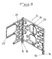
- the means 2 for horizontal adjustment of the formwork and for assembling said formwork in a superimposed position and the means 3 for assembling the vertical edges of adjacent formwork 1 are advantageously produced in the form of boxes made of composite material directly integrated into the infrastructure of the panel 1 by form cooperation and by bonding. Indeed, as shown more particularly in Figures 4 to 8, said boxes forming the means 2 and 3 are inserted in cutouts made in the reinforcement infrastructure of the panel 1 and can be assembled to this infrastructure by gluing.
- FIG. 4 of the accompanying drawings shows more particularly the implementation of means 3 for assembling the edges vertical of neighboring forms 1.
- These means 3 each comprise, in addition to a box to be built into the infrastructure of the panel 1, a screw 3 'or a nut 3 "cooperating with a corresponding guide sleeve 3"', respectively 3 "", and a retaining means 6-6 'of the 3' screw or 3 "nut in the housing, in the non-use position.
- the 6-6 'means of retaining the 3' screw or 3" nut is preferably constituted by a longitudinal axis 6 extending substantially parallel to the axis of the screw 3 'or of the nut 3 "in the service position and by a connecting lug 6', connected to the head of the screw 3 'or to a end of the nut 3 "with freedom of rotation and guided in translation on the longitudinal axis 6.
- the longitudinal axis 6 is advantageously produced in the form of a metal rod crimped at its ends in the corresponding edges of the housings forming the means 3 and the mounting of this axis 6, as well as the screw 3 'or the nut 3 ", can be carried out before fixing of the housing forming the means 3 in the infrastructure.
- the guide bushings 3 "'and 3" " can be in the form of attached bushings provided at one end with a shoulder supporting against the external face of the housing, this shoulder being housed in a corresponding passage hole from the edge of the infrastructure of the panel 1 and, on its internal face, of a means for immobilizing said socket, such as a nut screwed on said end.
- a means for immobilizing said socket such as a nut screwed on said end.
- the nut 3 has, on its side opposite to that connected to the connecting lug 6 ', a frustoconical part intended to cooperate with a corresponding conical recess of the corresponding guide bush 3""and the bush 3"'guide screw 3' has a central bore of diameter slightly larger than that of screw 3 ', the side of this socket 3 "' opposite to that on which the head of the screw 3 'is provided with 'a conical bore of conicity corresponding to that of the recess of the guide sleeve 3 "" of the nut 3 ".
- the sockets 3 "'and 3”" are placed substantially in extension of one another, then the nut 3" and the screw 3' are inserted in the recess and in the corresponding respective hole and the screw 3 'is tightened in the nut 3'.
- sockets 3 "'and 3"" align perfectly with each other and, due to the identical positioning of these sockets in the housing forming the means 3, at a predetermined distance from the formwork surface of the form 1, the formwork surfaces of two adjacent forms are perfectly aligned.
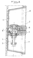
- the means 2 for horizontal adjustment of the formwork and for assembling said formwork in superimposed position are essentially constituted by housings 7 for upper assembly and lifting and housings 8 for assembly lower and lifting, which are mounted in corresponding recesses formed in the upper and lower edges of the infrastructure of the panel 1, said housings 7 and 8 having a side flush with the corresponding edge of said infrastructure and being provided, respectively projection 9 and recess 10 of cooperating shape and aligned with a projection and an obviously threading on the corresponding side of the panel.
- projections 9 and recess 10 are intended to allow perfect nesting of the housings 7 and 8 during assembly by superposition.
- the boxes 7 and 8 are each provided, on the one hand, with a handle 7 ′, 8 ′ for hooking a lifting hook (FIGS. 5, 5A and 6A) and, on the other hand, at least one threaded connection sleeve 7 ", 8" and, respectively, a connection screw 7 "', 8"' and a mechanical jack 8 "'.
- the mechanical jack 8 "'provided in each housing 8 for lower assembly and lifting, shown more particularly in FIG. 6 of the accompanying drawings, has, in known manner, a shoe 8""enabling the planks to be adjusted vertically by displacement of said skate by screwing or unscrewing the body of said cylinder
- the operation of this cylinder can, for example, be carried out by means of an operating polygon or the like provided on the side opposite the shoe.
- Each platform 4 (FIG. 10) is advantageously constituted by at least one floor panel 11, molded from composite material, connected to at least one access hatch 12, by means of the infrastructure 13 of said access hatch 12, said panel 11 being fixed by its lower face on at least one cross-member 14 for pivoting mounting on the infrastructure of the panel 1.
- the panel 11 is fixed on the infrastructure 13 and on the mounting cross-member 14 by screwing or bolting.
- the railings 5 are preferably made in the form of molded plastic panels, these panels being provided with recesses and stiffening ribs, as well as, on their longitudinal edge intended to be mounted on the platform 4, legs 15 d '' in one piece with the railing 5 ( Figure 9).
- the lugs 15 for mounting the railings 5 on the platforms 4 are each provided with at least one hole 16 for the passage of a mounting pin 17 on an articulation means 18 secured to the platform 4, as well as a device 19 for locking the guardrails 5 in the service position (FIGS. 12 to 14).
- Each means 18 of articulation of the railings 5 on the platforms 4 is advantageously in the form of a tubular element for housing a tab 15 of the railing in the service position, this tubular element being connected at right angles to an arm 20 for fixing to a corresponding floor panel 11.
- the floor panel 11 is advantageously provided with at least one longitudinal housing 11 'intended for the insertion of the arm 20 of the articulation means 18, the end of this arm 20, opposite the tubular element. housing the tab 15 of the railing, extending under said floor panel 1 to which it is fixed by screwing or bolting ( Figures 10 and 11).
- the tubular element for housing the tab 15 of the railing 5 is provided, on two opposite faces perpendicular to the longitudinal edge of said railing 5 and perpendicular the legs 15 extending these panels, two vertical guide grooves 21 intended to cooperate with the mounting axis 17 of the legs 15, these grooves 21 being provided, in addition, at their upper part with a perpendicular groove part 21 ' .
- the grooves 21 are intended to allow, as shown in Figures 13 and 14 of the accompanying drawings, a vertical guide of the axis 17 and a corresponding insertion of the legs 15 of the railings 5 in the tubular element of the articulation means 18, the part of perpendicular upper grooves 21 ′ being intended to guide the axis 17 for tilting into the folded position of the railing 5 on the platform 4.
- the device 19 for locking the guardrails 5 in the service position is advantageously in the form of a hook lever loaded by a torsion spring 19 ', the hook 19 "of which cooperates, in the service position, with a recess 18 'provided in the tubular element of the articulation means 18.
- a guardrail 5 when placing a guardrail 5 in the service position, the latter is tilted a folding position parallel to a platform 4 to a position erected perpendicular to said platform 4 ( Figure 12).
- the mounting axis 17 of the lugs 15 penetrate into the groove 21 at the same time as said lugs 15 penetrate into the tubular element of the articulation means 18. This penetration of the lugs 15 has the effect of locking the railing 5 in its service position.
- the hook 19 "of the device 19 for blocking the guardrails 5 enters the recess 18 'provided in the means 18 and prevents any undesirable extraction of the legs 15 out of the service position.
- the device 19 will have the effect of pivoting the lever constituting it about its axis against the action of the torsion spring 19 '.
- the legs 15 can then be moved in the means 18 to be brought, upon arrival at the upper end of the groove 21 in the position allowing tilting of the railing 5 towards its folded position, the mounting pin 17 then penetrating into the perpendicular groove 21 '.
- the railings 5 fitted to an end panel can advantageously be provided with an end railing element 22, also under form of a panel of molded composite material, this panel 22 being pivotally mounted, against the action of torsion springs (not shown), along the corresponding vertical edge of the railing panel 5.
- the panel complementary end 22 can be folded up, in the non-use position against the panel forming the railing 5.
- the complementary end panel 22 has, on its internal face, recesses and ribs complementary to the ribs and recesses provided on the corresponding internal face of the railing panel 5.
- said panel 22 can be perfectly applied in the hollow elements of the railing panel 5, so that its size is reduced to a minimum.
- the railing panel 5 is advantageously provided with at least one immobilizing means in the folded position, in the form of a snap-on tab 23 cooperating with retaining hooks 24 of the railing 5, or of any other retaining elements by snap-fastening or by covering.
- the complementary end panel 22 can be provided with at least one extensible element 22 ′ slidably mounted in said panel 22 and which can be adjusted in the extended position.
- an extensible element 22 ′ may, for example, be in the form of a substantially U-shaped piece, the wings of which are each guided in corresponding guides of the panel 22 with the possibility of hard sliding or with the provision of an element of locking after position adjustment in the form of a screw or the like.
- the platforms 4 are mounted on the forms 5 with the possibility of pivoting by means of their mounting crosspieces 14 on the infrastructure of the formwork 1, the maintenance in the service position of said platforms 4 deployed together with their guard deployed body being provided by props 24 (FIGS. 1 to 3).
- these security elements are of a particularly low weight compared to the corresponding existing elements, so that their implementation can be greatly facilitated and can be carried out by an operator alone.
Priority Applications (1)
| Application Number | Priority Date | Filing Date | Title |
|---|---|---|---|
| EP02360294A EP1413696A1 (de) | 2002-10-24 | 2002-10-24 | Schalung in Verbundmaterial |
Applications Claiming Priority (1)
| Application Number | Priority Date | Filing Date | Title |
|---|---|---|---|
| EP02360294A EP1413696A1 (de) | 2002-10-24 | 2002-10-24 | Schalung in Verbundmaterial |
Publications (1)
| Publication Number | Publication Date |
|---|---|
| EP1413696A1 true EP1413696A1 (de) | 2004-04-28 |
Family
ID=32050130
Family Applications (1)
| Application Number | Title | Priority Date | Filing Date |
|---|---|---|---|
| EP02360294A Withdrawn EP1413696A1 (de) | 2002-10-24 | 2002-10-24 | Schalung in Verbundmaterial |
Country Status (1)
| Country | Link |
|---|---|
| EP (1) | EP1413696A1 (de) |
Cited By (7)
| Publication number | Priority date | Publication date | Assignee | Title |
|---|---|---|---|---|
| EP1878851A2 (de) * | 2006-07-12 | 2008-01-16 | Hussor (Société par Actions Simplifiée) | Verschalung mit einer Drehplattform mit automatischen Einrastverschluss in Betriebsposition |
| EP1975338A1 (de) | 2007-03-19 | 2008-10-01 | Hussor (Société par Actions Simplifiée) | Vorrichtung zum übereinander Anordnen von Schaltafeln |
| FR2941253A1 (fr) * | 2009-01-21 | 2010-07-23 | Sateco Sa | Banche de moulage d'un voile en beton, ensemble de banches assemblees entre elles. |
| FR2941252A1 (fr) * | 2009-01-21 | 2010-07-23 | Sateco Sa | Banche de moulage d'un voile en beton, ensemble de banches assemblees entre elles. |
| EP2599938A1 (de) * | 2011-12-01 | 2013-06-05 | Société Eurobress | Sicherheitssteg mit ausziehbarer Stützstrebe für Schalwand |
| FR2989406A1 (fr) * | 2012-04-13 | 2013-10-18 | Sateco Sa | Banche de coffrage comportant une plateforme de circulation avec une trappe articulee |
| CN112222347A (zh) * | 2020-09-18 | 2021-01-15 | 郑州机械研究所有限公司 | 一种多向挤压模架结构 |
Citations (5)
| Publication number | Priority date | Publication date | Assignee | Title |
|---|---|---|---|---|
| FR2470220A1 (fr) * | 1979-11-21 | 1981-05-29 | Husson Et Cie Sa Roland | Banche pour la realisation de murs, ou analogues |
| FR2598453A1 (fr) * | 1986-05-09 | 1987-11-13 | Husson Cie Sa R | Banche pour la realisation de murs, ou analogues |
| US5833872A (en) * | 1997-03-14 | 1998-11-10 | De Le Fevre; Patrick Y. | Forming device for settable fluids for use in construction |
| EP1118735A1 (de) * | 2000-01-18 | 2001-07-25 | Hussor S.A. | Schalungsvorrichtung in Verbundmaterial |
| WO2002048479A2 (en) * | 2000-12-13 | 2002-06-20 | Ezio Sedran | Modular elements for formworks |
-
2002
- 2002-10-24 EP EP02360294A patent/EP1413696A1/de not_active Withdrawn
Patent Citations (5)
| Publication number | Priority date | Publication date | Assignee | Title |
|---|---|---|---|---|
| FR2470220A1 (fr) * | 1979-11-21 | 1981-05-29 | Husson Et Cie Sa Roland | Banche pour la realisation de murs, ou analogues |
| FR2598453A1 (fr) * | 1986-05-09 | 1987-11-13 | Husson Cie Sa R | Banche pour la realisation de murs, ou analogues |
| US5833872A (en) * | 1997-03-14 | 1998-11-10 | De Le Fevre; Patrick Y. | Forming device for settable fluids for use in construction |
| EP1118735A1 (de) * | 2000-01-18 | 2001-07-25 | Hussor S.A. | Schalungsvorrichtung in Verbundmaterial |
| WO2002048479A2 (en) * | 2000-12-13 | 2002-06-20 | Ezio Sedran | Modular elements for formworks |
Cited By (12)
| Publication number | Priority date | Publication date | Assignee | Title |
|---|---|---|---|---|
| EP1878851A2 (de) * | 2006-07-12 | 2008-01-16 | Hussor (Société par Actions Simplifiée) | Verschalung mit einer Drehplattform mit automatischen Einrastverschluss in Betriebsposition |
| FR2903716A1 (fr) * | 2006-07-12 | 2008-01-18 | Hussor Soc Par Actions Simplif | Banche pourvue d'une plateforme de circulation a verrouillage automatique en position de service |
| EP1878851A3 (de) * | 2006-07-12 | 2009-03-18 | Hussor (Société par Actions Simplifiée) | Verschalung mit einer Drehplattform mit automatischen Einrastverschluss in Betriebsposition |
| EP1975338A1 (de) | 2007-03-19 | 2008-10-01 | Hussor (Société par Actions Simplifiée) | Vorrichtung zum übereinander Anordnen von Schaltafeln |
| FR2941253A1 (fr) * | 2009-01-21 | 2010-07-23 | Sateco Sa | Banche de moulage d'un voile en beton, ensemble de banches assemblees entre elles. |
| FR2941252A1 (fr) * | 2009-01-21 | 2010-07-23 | Sateco Sa | Banche de moulage d'un voile en beton, ensemble de banches assemblees entre elles. |
| EP2211001A1 (de) * | 2009-01-21 | 2010-07-28 | Sateco | Schalung zum Giessen von einer Betonmauer, Anordnung von miteinander verknüpften Schalungen |
| EP2599938A1 (de) * | 2011-12-01 | 2013-06-05 | Société Eurobress | Sicherheitssteg mit ausziehbarer Stützstrebe für Schalwand |
| FR2983505A1 (fr) * | 2011-12-01 | 2013-06-07 | Eurobress | Passerelle de securite a etai depliable pour banche de coffrage |
| FR2989406A1 (fr) * | 2012-04-13 | 2013-10-18 | Sateco Sa | Banche de coffrage comportant une plateforme de circulation avec une trappe articulee |
| CN112222347A (zh) * | 2020-09-18 | 2021-01-15 | 郑州机械研究所有限公司 | 一种多向挤压模架结构 |
| CN112222347B (zh) * | 2020-09-18 | 2022-08-26 | 郑州机械研究所有限公司 | 一种多向挤压模架结构 |
Similar Documents
| Publication | Publication Date | Title |
|---|---|---|
| EP1905921B1 (de) | Perfektionierte Faltkonstruktion für Arbeiten im Freivorbau | |
| EP0296916A1 (de) | Modulares Bauelement, insbesondere für Leitern oder Gerüste | |
| EP3199723A1 (de) | Selbsttragende geländer | |
| FR2704260A1 (fr) | Procédé de cintrage de parois coffrantes, et parois coffrantes cintrables faisant application de ce procédé. | |
| FR2598453A1 (fr) | Banche pour la realisation de murs, ou analogues | |
| EP1413696A1 (de) | Schalung in Verbundmaterial | |
| FR2941480A1 (fr) | Potelet de garde-corps de securite et un garde-corps de securite comprenant au moins un tel potelet | |
| EP2599938B1 (de) | Sicherheitssteg mit ausziehbarer Stützstrebe für Schalwand | |
| WO1996002716A1 (fr) | Escalier a configuration variable | |
| FR2470220A1 (fr) | Banche pour la realisation de murs, ou analogues | |
| FR2863291A1 (fr) | Garde-corps pour plate-forme de coffrage et element de plate-forme avec garde-corps | |
| EP0674741A1 (de) | Justierbares gerüst für schiefe oberflächen | |
| FR2913999A1 (fr) | Dispositif de superposition de banches | |
| EP1013848B1 (de) | Dachgerüst | |
| FR2990985A1 (fr) | Echelle de toit notamment pour couvreurs | |
| EP0282385B1 (de) | Vorrichtung zur Verankerung an Dachsparren bei Dacharbeiten | |
| FR2913998A1 (fr) | Dispositif de maintien de tige exterieur | |
| EP1878851A2 (de) | Verschalung mit einer Drehplattform mit automatischen Einrastverschluss in Betriebsposition | |
| FR2956424A1 (fr) | Plateforme de travail en encorbellement | |
| EP1270845B1 (de) | Arbeitsbühne für eine Schalungsvorrichtung mit einstellbarem Krümmungsradius | |
| FR2990986A1 (fr) | Echelle de toit, notamment pour couvreur | |
| EP0580456B1 (de) | Gerüst | |
| FR2927103A3 (fr) | Banche pour la realisation de murs ou de voiles | |
| FR2927919A1 (fr) | Element d'echafaudage et ensemble d'echafaudage comprenant un tel element | |
| EP1647648B1 (de) | Verbindungsvorrichtung zwischen einem Eckpfosten und zwei Füllelementen in einem Geländer |
Legal Events
| Date | Code | Title | Description |
|---|---|---|---|
| PUAI | Public reference made under article 153(3) epc to a published international application that has entered the european phase |
Free format text: ORIGINAL CODE: 0009012 |
|
| AK | Designated contracting states |
Kind code of ref document: A1 Designated state(s): AT BE BG CH CY CZ DE DK EE ES FI FR GB GR IE IT LI LU MC NL PT SE SK TR |
|
| AX | Request for extension of the european patent |
Extension state: AL LT LV MK RO SI |
|
| 17P | Request for examination filed |
Effective date: 20041020 |
|
| AKX | Designation fees paid |
Designated state(s): AT BE BG CH CY CZ DE DK EE ES FI FR GB GR IE IT LI LU MC NL PT SE SK TR |
|
| STAA | Information on the status of an ep patent application or granted ep patent |
Free format text: STATUS: THE APPLICATION HAS BEEN WITHDRAWN |
|
| 18W | Application withdrawn |
Effective date: 20091029 |