EP1413515A2 - Vorrichtung zur Ansteuerung der Vorflügel und Landeklappen eines Flugzeuges - Google Patents
Vorrichtung zur Ansteuerung der Vorflügel und Landeklappen eines Flugzeuges Download PDFInfo
- Publication number
- EP1413515A2 EP1413515A2 EP03023459A EP03023459A EP1413515A2 EP 1413515 A2 EP1413515 A2 EP 1413515A2 EP 03023459 A EP03023459 A EP 03023459A EP 03023459 A EP03023459 A EP 03023459A EP 1413515 A2 EP1413515 A2 EP 1413515A2
- Authority
- EP
- European Patent Office
- Prior art keywords
- flaps
- slats
- adjusting
- lever mechanism
- command
- Prior art date
- Legal status (The legal status is an assumption and is not a legal conclusion. Google has not performed a legal analysis and makes no representation as to the accuracy of the status listed.)
- Granted
Links
- 241000446313 Lamella Species 0.000 claims description 2
- 239000002184 metal Substances 0.000 claims description 2
- 230000011664 signaling Effects 0.000 description 4
- 238000000034 method Methods 0.000 description 2
- 230000000903 blocking effect Effects 0.000 description 1
- 238000010586 diagram Methods 0.000 description 1
- 230000008030 elimination Effects 0.000 description 1
- 238000003379 elimination reaction Methods 0.000 description 1
- 230000014759 maintenance of location Effects 0.000 description 1
- 238000012544 monitoring process Methods 0.000 description 1
Images
Classifications
-
- G—PHYSICS
- G05—CONTROLLING; REGULATING
- G05G—CONTROL DEVICES OR SYSTEMS INSOFAR AS CHARACTERISED BY MECHANICAL FEATURES ONLY
- G05G1/00—Controlling members, e.g. knobs or handles; Assemblies or arrangements thereof; Indicating position of controlling members
- G05G1/04—Controlling members for hand actuation by pivoting movement, e.g. levers
-
- B—PERFORMING OPERATIONS; TRANSPORTING
- B64—AIRCRAFT; AVIATION; COSMONAUTICS
- B64C—AEROPLANES; HELICOPTERS
- B64C13/00—Control systems or transmitting systems for actuating flying-control surfaces, lift-increasing flaps, air brakes, or spoilers
- B64C13/02—Initiating means
- B64C13/04—Initiating means actuated personally
- B64C13/042—Initiating means actuated personally operated by hand
- B64C13/0425—Initiating means actuated personally operated by hand for actuating trailing or leading edge flaps, air brakes or spoilers
-
- G—PHYSICS
- G05—CONTROLLING; REGULATING
- G05G—CONTROL DEVICES OR SYSTEMS INSOFAR AS CHARACTERISED BY MECHANICAL FEATURES ONLY
- G05G9/00—Manually-actuated control mechanisms provided with one single controlling member co-operating with two or more controlled members, e.g. selectively, simultaneously
Definitions
- the invention relates to a device for controlling the slats and flaps of an aircraft using a command transmitter designed as a lever mechanism for generating command commands for adjusting the slats and flaps, the lever mechanism having a lever linkage mechanically connected to two rotatable sensor disks, and with each sensor disk Signal transmitters are equipped, which are electrically connected to two flight computers for determining and forwarding control signals to adjusting devices of the slats and flaps of the right and left wing.
- a command transmitter designed as a lever mechanism for generating command commands for adjusting the slats and flaps
- the lever mechanism having a lever linkage mechanically connected to two rotatable sensor disks, and with each sensor disk Signal transmitters are equipped, which are electrically connected to two flight computers for determining and forwarding control signals to adjusting devices of the slats and flaps of the right and left wing.
- Previous aircraft have a command transmitter with a simple load path with regard to the target commands, the slats and flaps being controlled and monitored by means of two flight computers, to which the command command is fed via a single lever mechanism with associated signal transmitters.
- This lever mechanism has a control link with a certain number of notches, which is a command transmitter in the form of a lever hold in a fixed position.
- blocking means designed as baffles are provided, which prevent the lever from being moved from the zero to the full position or vice versa in one setting operation, without stopping in the intermediate positions.
- This command transmitter has the disadvantage that if the singular mechanics or sensors fail, for example due to breakage or mechanical jamming within the load path or within the sensors, the entire slat and flap system can no longer be activated.
- an alternative control switch can also be introduced. However, this means accommodating additional switches in the cockpit and special procedures for the pilots in the event that the normal command transmitter is not available.
- the invention has for its object to provide a device of the type mentioned, in which a mechanical break or jamming of a drive / load path or a failure of a signal transmitter does not lead to the loss of the function "landing flap command".
- lever mechanism is carried out twice and is divided into two load paths that are independent in their design but coupled in their function in such a way that two adjusting levers and two linkages are functionally combined to form a command transmitter, and that the signal transmitters of an associated sensor disk each are connected to one of the two flight computers.
- An advantage of the invention in addition to dispensing with additional alternative switches including alternative cockpit procedures, is that the probability of a total failure of the command transmitter for the redundant flight computers can be reduced to ⁇ 10 -9 / FH.
- two redundant adjustment levers are functionally combined to form an operating lever by means of mechanical synchronization (bolts / rivets or the like).
- a mechanical break in a drive / load path or the complete failure of a signal transmitter does not lead to the loss of the "flap command" function, since the second path not affected still enables a lever function including a valid command from the sensors.
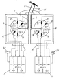
- the lever mechanism of the device according to FIG. 1 has two adjusting levers 3 and 4 and two linkages 5 and 6.
- the linkages 5, 6 are mechanically connected on the one hand to the adjusting levers 3, 4 and on the other hand to a rotatable sensor disk 7 and 8, respectively.
- the adjusting lever 3, 4 and the linkage 5, 6 are functionally combined to form a command transmitter.
- Every sensor disc 7 and 8 have four signal transmitters, for example signal transmitter 12 for slat computer / processor 1.1, signal transmitter 13 for slat computer / processor 1.2, signal transmitter 14 for flap computer / processor 1.1, signal transmitter 15 for flap computer / processor 1.2, Signal generator 16 for slat computer / processor 2.1, signal generator 17 for slat computer / processor 2.2, signal generator 18 for flap computer / processor 2.1 and signal generator 19 for flap computer / processor 2.2. All signal generators 12 to 15 or 16 to 19 of an associated sensor disk 7 or 8 are each electrically connected to the associated flight computer 1 or 2 via a first or second electrical connecting element 9 or 10, for example with the aid of electrical plugs.
- a first and second reset switch in the so-called overhead panel is designated by 20 and 21, respectively.
- the lever mechanism is constructed in such a way that a jamming of a sensor disk 7 or 8 can always be suppressed by - possibly increased - operating forces.
- the side of the redundant lever mechanism that is not affected by the clamping can still give valid control commands to the flight computer 1 or 2 via the redundant sensor system.
- the adjusting levers 3 and 4 lead in a blockage-free setting 11, in which the catches on one side and the baffles on the other side of the adjusting levers 3 and 4 are arranged. Loose or sheared parts can not lead to a blockage.
- this slot will have a mechanical cover in the form of a roller or lamella door, an accordion or a movable sheet metal / plastic cover.
Landscapes
- Engineering & Computer Science (AREA)
- Automation & Control Theory (AREA)
- Physics & Mathematics (AREA)
- General Physics & Mathematics (AREA)
- Aviation & Aerospace Engineering (AREA)
- Safety Devices In Control Systems (AREA)
- Mechanical Control Devices (AREA)
- Power-Operated Mechanisms For Wings (AREA)
- Train Traffic Observation, Control, And Security (AREA)
Abstract
Description
- Die Erfindung betrifft eine Vorrichtung zur Ansteuerung der Vorflügel und Landeklappen eines Flugzeuges unter Verwendung eines als Hebelmechanismus ausgeführten Kommandogebers zur Erzeugung von Sollkommandos für eine Verstellung der Vorflügel und Landeklappen, wobei der Hebelmechanismus ein mit zwei drehbaren Sensorscheiben mechanisch verbundenes Hebelgestänge aufweist, und wobei jede Sensorscheibe mit Signalgebern ausgestattet ist, die an zwei Flugrechner zur Ermittlung und Weiterleitung von Stellsignalen an Verstelleinrichtungen der Vorflügel und Landeklappen des rechten und des linken Flügels elektrisch angeschlossen sind.
- Bisherige Flugzeuge besitzen einen Kommandogeber mit einem einfachen Lastpfad hinsichtlich der Sollkommandos, wobei die Vorflügel und Landeklappen mittels zweier Flugrechner, denen über einen einzigen Hebelmechanismus mit zugehörigen Signalgebern das Sollkommando zugeführt wird, angesteuert und überwacht werden. Dieser Hebelmechanismus besitzt eine Steuerkulisse mit einer bestimmten Anzahl von Rasten, die einen Kommandogeber in Form eines Hebels in einer fixierten Stellung halten. Weiterhin sind als Schikanen ausgebildete Sperrmittel vorgesehen, die verhindern, daß der Hebel in einem Stellvorgang von der Null- auf die Vollstellung oder umgekehrt bewegt werden kann, ohne in den Zwischenstellungen anzuhalten. Bei diesem Kommandogeber besteht der Nachteil, daß bei Ausfall der singulären Mechanik oder Sensorik, beispielsweise durch Bruch oder mechanisches Klemmen innerhalb des Lastpfades oder innerhalb der Sensorik, das gesamte Vorflügel- und Landeklappensystem nicht mehr angesteuert werden kann. Um die Abhängigkeit des gesamten Systems von der Verfügbarkeit nur eines Kommandogebers zu vermeiden, kann ein alternativer Kontrollschalter zusätzlich eingeführt werden. Dieses bedeutet aber die Unterbringung von zusätzlichen Schaltern im Cockpit und spezielle Prozeduren für die Piloten im Falle der Nichtverfügbarkeit des normalen Kommandogebers.
- Der Erfindung liegt nun die Aufgabe zugrunde, eine Vorrichtung der eingangs genannten Art zu schaffen, bei der ein mechanischer Bruch oder ein Klemmen eines Antrieb-/Lastpfades bzw. ein Ausfall eines Signalgebers nicht zum Verlust der Funktion "Landeklappenkommando" führt.
- Die Aufgabe wird erfindungsgemäß dadurch gelöst, daß der Hebelmechanismus doppelt ausgeführt und in zwei in ihrer Auslegung unabhängige aber in ihrer Funktion gekoppelte Lastpfade derart aufgeteilt ist, daß zwei Verstellhebel und zwei Gestänge funktional zu einem Kommandogeber zusammengefaßt sind, und daß die Signalgeber einer zugehörigen Sensorscheibe jeweils an einen der beiden Flugrechner angeschlossen sind.
- Ausgestaltungen der Erfindung sind in den Unteransprüchen 2 und 3 beschrieben.
- Ein Vorteil der Erfindung liegt neben dem Verzicht auf zusätzliche alternative Schalter inklusive alternativer Cockpit-Prozeduren darin, daß die Wahrscheinlichkeit eines Totalausfalles des Kommandogebers für die redundanten Flugrechner auf < 10-9/FH reduziert werden kann. Mit der erfindungsgemäßen Vorrichtung werden zwei redundante Verstellhebel funktional zu einem Bedienhebel mittels mechanischer Synchronization (Bolzen/Nieten o.ä) zusammengefaßt. Ein mechanischer Bruch eines Antriebs-/Lastpfades oder der komplette Ausfall eines Signalgebers führt nicht zum Verlust der Funktion "Landeklappenkommando", da der zweite nicht betroffene Pfad weiterhin eine Hebelfunktion inklusive gültigem Stellkommando über die Sensorik ermöglicht. Mit dem Wegfall der Notwendigkeit eines alternativen Bedienknopfes oder -hebels ist eine signifikante Vereinfachung der Systemauslegung (Rechnerfunktionalitäten, Cockpitinterface) sowie eine Beibehaltung bisheriger Bedienfunktionalität vorteilhafterweise verbunden.
- In der Zeichnung ist ein Ausführungsbeispiel nach der Erfindung dargestellt, und zwar zeigt die einzige Figur eine Prinzipdarstellung einer Vorrichtung zur Ansteuerung und Überwachung von zeicherisch nicht dargestellten Vorflügeln und Landeklappen eines Flugzeuges. Hierbei werden ebenfalls nicht dargestellte Verstelleinrichtungen der Vorflügel und Landklappen von zwei Flugrechnern 1 und 2 mit Verstellsignalen beaufschlagt.
- Der Hebelmechanismus der Vorrichtung nach Fig. 1 weist zwei Verstellhebel 3 und 4 sowie zwei Gestänge 5 und 6 auf. Die Gestänge 5, 6 sind einerseits mit den Verstellhebeln 3, 4 sowie andererseits mit jeweils einer drehbaren Sensorscheibe 7 bzw. 8 mechanisch verbunden. Hierbei sind die Verstellhebel 3, 4 und die Gestänge 5, 6 funktional zu einem Kommandogeber zusammengefaßt. Jede Sensorscheibe 7 bzw. 8 weist vier Signalgeber auf, beispielsweise Signalgeber 12 für Vorflügel-Rechner/Prozessor 1.1, Signalgeber 13 für Vorflügel-Rechner/Prozessor 1.2, Signalgeber 14 für Landeklappen-Rechner/Prozessor 1.1, Signalgeber 15 für Landeklappen-Rechner/Prozessor 1.2, Signalgeber 16 für Vorflügel-Rechner/Prozessor 2.1, Signalgeber 17 für Vorflügel-Rechner/Prozessor 2.2, Signalgeber 18 für Landeklappen-Rechner/Prozessor 2.1 und Signalgeber 19 für Landeklappen-Rechner/Prozessor 2.2. Alle Signalgeber 12 bis 15 bzw. 16 bis 19 einer zugehörigen Sensorscheibe 7 bzw. 8 sind jeweils über ein erstes oder zweites elektrisches Verbindungselement 9 bzw. 10, beispielsweise mit Hilfe von elektrischen Steckern, an den zugehörigen Flugrechner 1 bzw. 2 elektrisch angeschlossen. Mit 20 bzw. 21 ist jeweils ein erster bzw. zweiter Reset-Schalter im sogenannten Overhead-Panel bezeichnet.
- Vorteilhafterweise ist der Hebelmechanismus so konstruiert, daß ein Klemmen einer Sensorscheibe 7 oder 8 immer durch - gegebenenfalls erhöhte - Bedienkräfte überdrückt werden kann. Die vom Klemmen nicht betroffene Seite des redundanten Hebelmechanismus kann weiterhin gültige Stellkommandos über die redundante Sensorik an die Flugrechner 1 oder 2 geben. Außerdem ist vorgesehen, daß die Verstellhebel 3 und 4 in einer blockadefrei ausgebildeten Kulisse 11 zu führen, bei der die Rasten auf einer Seite und die Schikanen auf der anderen Seite der Verstellhebel 3 bzw. 4 angeordnet sind. Somit können lose oder abgescherte Teile nicht zu einer Blockade führen. Damit keine unerwünschten Fremdkörper in den die Verstellhebel 3 bzw. 4 führenden Schlitz der Steuerkulisse 11 eindringen können, wird dieser Schlitz eine mechanische Abdeckung in Form einer Roll- oder Lamellentür, einer Ziehharmonika oder einer beweglichen Blech-/Kunststoffabdeckung aufweisen.
-
- 1
- erster Flugrechner
- 2
- zweiter Flugrechner
- 3
- erster Verstellhebel
- 4
- zweiter Verstellhebel
- 5
- erstes Gestänge
- 6
- zweites Gestänge
- 7
- erste drehbare Sensorscheibe
- 8
- zweite drehbare Sensorscheibe
- 9
- erstes elektrisches Verbindungselement (Stecker)
- 10
- zweites elektrisches Verbindungselement (Stecker)
- 11
- Kulisse
- 12
- Signalgeber für Vorflügel-Rechner/Prozessor 1.1
- 13
- Signalgeber für Vorflügel-Rechner/Prozessor 1.2
- 14
- Signalgeber für Landeklappen-Rechner/Prozessor 1.1
- 15
- Signalgeber für Landeklappen-Rechner/Prozessor 1.2
- 16
- Signalgeber für Vorflügel-Rechner/Prozessor 2.1
- 17
- Signalgeber für Vorflügel-Rechner/Prozessor 2.2
- 18
- Signalgeber für Landeklappen-Rechner/Prozessor 2.1
- 19
- Signalgeber für Landeklappen-Rechner/Prozessor 2.2
- 20
- erster Reset-Schalter im Overhead-Panel
- 21
- zweiter Reset-Schalter im Overhead-Panel
Claims (3)
- Vorrichtung zur Ansteuerung der Vorflügel und Landeklappen eines Flugzeuges unter Verwendung eines als Hebelmechanismus ausgeführten Kommandogebers zur Erzeugung von Sollkommandos für eine Verstellung der Vorflügel und Landeklappen, wobei der Hebelmechanismus ein mit zwei drehbaren Sensorscheiben mechanisch verbundenes Hebelgestänge aufweist, und wobei jede Sensorscheibe mit Signalgebern ausgestattet ist, die an zwei Flugrechner zur Ermittlung und Weiterleitung von Stellsignalen an Verstelleinrichtungen der Vorflügel und Landeklappen des rechten und des linken Flügels elektrisch angeschlossen sind,
dadurch gekennzeichnet, daß der Hebelmechanismus doppelt ausgeführt und in zwei in ihrer Auslegung unabhängige aber in ihrer Funktion gekoppelte Lastpfade derart aufgeteilt ist, daß zwei Verstellhebel (3, 4) und zwei Gestänge (5, 6) funktional zu einem Kommandogeber zusammengefaßt sind, und daß die Signalgeber (12 bis 15 bzw. 16 bis 19) einer zugehörigen Sensorscheibe (7 bzw. 8) jeweils an einen der beiden Flugrechner (1 bzw. 2) elektrisch angeschlossen sind. - Vorrichtung nach Anspruch 1, dadurch gekennzeichnet, daß die Verstellhebel (3, 4) in einer blockadefrei ausgebildeten Kulisse (11) geführt sind, bei der die Rasten auf einer Seite und die Schikanen auf der anderen Seite der Verstellhebel (3, 4) angeordnet sind.
- Vorrichtung nach Anspruch 2, dadurch gekennzeichnet, daß die die Verstellhebel (3, 4) führenden Schlitze der Kulisse (11) eine mechanische Abdeckung in Form einer Roll- oder Lamellentür, einer Ziehharmonika oder einer beweglichen Blech-/Kunststoffabdeckung aufweisen.
Applications Claiming Priority (2)
| Application Number | Priority Date | Filing Date | Title |
|---|---|---|---|
| DE10249967 | 2002-10-26 | ||
| DE10249967A DE10249967B4 (de) | 2002-10-26 | 2002-10-26 | Vorrichtung zur Ansteuerung der Vorflügel und Landeklappen eines Flugzeuges |
Publications (3)
| Publication Number | Publication Date |
|---|---|
| EP1413515A2 true EP1413515A2 (de) | 2004-04-28 |
| EP1413515A3 EP1413515A3 (de) | 2005-06-29 |
| EP1413515B1 EP1413515B1 (de) | 2006-05-03 |
Family
ID=32049625
Family Applications (1)
| Application Number | Title | Priority Date | Filing Date |
|---|---|---|---|
| EP03023459A Expired - Lifetime EP1413515B1 (de) | 2002-10-26 | 2003-10-18 | Vorrichtung zur Ansteuerung der Vorflügel und Landeklappen eines Flugzeuges |
Country Status (4)
| Country | Link |
|---|---|
| US (1) | US6804586B2 (de) |
| EP (1) | EP1413515B1 (de) |
| AT (1) | ATE325035T1 (de) |
| DE (2) | DE10249967B4 (de) |
Cited By (8)
| Publication number | Priority date | Publication date | Assignee | Title |
|---|---|---|---|---|
| RU2507115C2 (ru) * | 2012-04-10 | 2014-02-20 | Открытое акционерное общество "Авиационный комплекс имени С.В. Ильюшина" | Сдвоенная ручка блока переключателей резервного управления механизацией предкрылков и закрылков крыла самолёта |
| RU2507116C2 (ru) * | 2012-04-10 | 2014-02-20 | Открытое акционерное общество "Авиационный комплекс имени С.В. Ильюшина" | Блок переключателей приводов резервного управления механизацией предкрылков |
| RU2507117C2 (ru) * | 2012-04-10 | 2014-02-20 | Открытое акционерное общество "Авиационный комплекс имени С.В. Ильюшина" | Блок переключателей приводов резервного управления механизацией закрылков |
| CN104812667A (zh) * | 2012-11-27 | 2015-07-29 | 庞巴迪公司 | 用于变速杆的故障检测机构 |
| EP3461739A1 (de) * | 2017-09-28 | 2019-04-03 | Hamilton Sundstrand Corporation | Halterungsteilüberwachungssystem für vorflügel-landeklappe-steuerhebel |
| RU2753997C1 (ru) * | 2020-12-29 | 2021-08-25 | Публичное акционерное общество "Объединенная авиастроительная корпорация" | Пульт резервного управления механизацией крыла самолёта |
| RU2753999C1 (ru) * | 2020-12-29 | 2021-08-25 | Публичное акционерное общество "Объединенная авиастроительная корпорация" | Переключатель режимов управления механизацией крыла самолёта |
| CN117341959A (zh) * | 2023-11-10 | 2024-01-05 | 中国商用飞机有限责任公司北京民用飞机技术研究中心 | 襟缝翼操作手柄及飞行器 |
Families Citing this family (18)
| Publication number | Priority date | Publication date | Assignee | Title |
|---|---|---|---|---|
| US7430135B2 (en) * | 2005-12-23 | 2008-09-30 | Grandis Inc. | Current-switched spin-transfer magnetic devices with reduced spin-transfer switching current density |
| DE102006030315A1 (de) * | 2006-06-30 | 2008-01-17 | Airbus Deutschland Gmbh | Hochauftriebssystem am Tragflügel eines Flugzeugs |
| US20090195416A1 (en) * | 2008-02-01 | 2009-08-06 | Michael Goren | Input assembly and technique for improved data entry |
| GB0823392D0 (en) * | 2008-12-23 | 2009-01-28 | Goodrich Actuation Systems Ltd | Drive arrangement |
| US8451144B2 (en) * | 2009-02-04 | 2013-05-28 | Honeywell International Inc. | Flaps overspeed advisory system |
| RU2507114C2 (ru) * | 2012-04-19 | 2014-02-20 | Открытое акционерное общество "Авиационный комплекс имени С.В. Ильюшина" | Пульт управления закрылками и предкрылками крыла летательного аппарата (варианты) |
| RU2506201C2 (ru) * | 2012-04-19 | 2014-02-10 | Открытое акционерное общество "Авиационный комплекс имени С.В. Ильюшина" | Переключатель основного управления механизацией крыла самолета (варианты), рычаг основного управления механизацией крыла самолета, гашетка командного блока основного управления механизацией крыла, силовой корпус командного блока переключателя основного управления механизацией крыла самолета |
| US9327826B2 (en) * | 2012-10-25 | 2016-05-03 | Textron Innovations Inc. | Self-centering aircraft flap position command apparatus |
| US9254909B2 (en) * | 2013-09-24 | 2016-02-09 | The Boeing Company | Optimized flap positioning for go-around operations |
| US9359065B2 (en) * | 2013-09-24 | 2016-06-07 | The Boeing Company | System and method for optimizing performance of an aircraft |
| US9771143B2 (en) * | 2014-09-24 | 2017-09-26 | Hamilton Sundstrand Corporation | Selector lever with independent slides |
| US20160085258A1 (en) * | 2014-09-24 | 2016-03-24 | Hamilton Sundstrand Corporation | Selector lever with failure indication features |
| US10086924B2 (en) * | 2016-04-29 | 2018-10-02 | Hamilton Sundstrand Corporation | Alignment device for a selector lever |
| US10372149B2 (en) * | 2016-07-13 | 2019-08-06 | Hamilton Sundstrand Corporation | Detent alignment mechanism assembly |
| CN107187582B (zh) * | 2017-07-31 | 2019-10-29 | 中国商用飞机有限责任公司 | 一种襟缝翼操纵手柄 |
| US11299256B2 (en) * | 2019-05-15 | 2022-04-12 | Textron Innovations, Inc. | Flap lever |
| US12351295B2 (en) * | 2022-11-21 | 2025-07-08 | Hamilton Sundstrand Corporation | Fiber optic slat flap system and control lever |
| US12673764B2 (en) * | 2023-12-29 | 2026-07-07 | Honeywell International Inc. | Multipivot user interface devices and related vehicle systems and methods |
Family Cites Families (12)
| Publication number | Priority date | Publication date | Assignee | Title |
|---|---|---|---|---|
| FR1484907A (fr) * | 1966-06-21 | 1967-06-16 | M A N Turbo G M B H | Dispositif de manoeuvre de giravions, en particulier d'hélicoptères et autogires combinés |
| US3850388A (en) * | 1972-03-23 | 1974-11-26 | Nasa | Integrated lift/drag controller for aircraft |
| DE2807902C2 (de) * | 1978-02-24 | 1980-04-30 | Messerschmitt-Boelkow-Blohm Gmbh, 8000 Muenchen | Steuereinrichtung mit aktiver Kraft rückführung |
| DE2919431A1 (de) * | 1979-05-15 | 1980-11-27 | Ver Flugtechnische Werke | Steuereinrichtung zum einstellen von luftfahrzeugsteuerflaechen |
| US4363098A (en) * | 1980-06-24 | 1982-12-07 | The Boeing Company | Electric command spoiler system |
| US4393730A (en) * | 1980-11-24 | 1983-07-19 | Mcdonnell Douglas Corporation | Unidirectional detent gate |
| US5077671A (en) * | 1989-07-05 | 1991-12-31 | The Boeing Company | Test cart for aircraft control surface measurements |
| DE8915839U1 (de) * | 1989-11-27 | 1992-01-16 | Bodenseewerk Gerätetechnik GmbH, 7770 Überlingen | Stellungssensor für Landeklappenhebel bei Flugzeugen |
| FR2708769B1 (fr) * | 1993-07-30 | 1995-11-10 | Aerospatiale | Système de contrôle d'une installation comportant plusieurs circuits indépendants en parallèle et nécessitant un haut niveau de sécurité. |
| US6038498A (en) * | 1997-10-15 | 2000-03-14 | Dassault Aviation | Apparatus and mehod for aircraft monitoring and control including electronic check-list management |
| FR2811780B1 (fr) * | 2000-07-13 | 2002-08-30 | Aerospatiale Matra Airbus | Procede et dispositif de commande d'organes de manoeuvre d'un aeronef, a modules de secours electriques |
| US6664656B2 (en) * | 2000-09-14 | 2003-12-16 | The Boeing Company | Aircraft electrical power distribution network |
-
2002
- 2002-10-26 DE DE10249967A patent/DE10249967B4/de not_active Expired - Fee Related
-
2003
- 2003-10-18 DE DE50303170T patent/DE50303170D1/de not_active Expired - Lifetime
- 2003-10-18 EP EP03023459A patent/EP1413515B1/de not_active Expired - Lifetime
- 2003-10-18 AT AT03023459T patent/ATE325035T1/de not_active IP Right Cessation
- 2003-10-27 US US10/695,618 patent/US6804586B2/en not_active Expired - Lifetime
Cited By (10)
| Publication number | Priority date | Publication date | Assignee | Title |
|---|---|---|---|---|
| RU2507115C2 (ru) * | 2012-04-10 | 2014-02-20 | Открытое акционерное общество "Авиационный комплекс имени С.В. Ильюшина" | Сдвоенная ручка блока переключателей резервного управления механизацией предкрылков и закрылков крыла самолёта |
| RU2507116C2 (ru) * | 2012-04-10 | 2014-02-20 | Открытое акционерное общество "Авиационный комплекс имени С.В. Ильюшина" | Блок переключателей приводов резервного управления механизацией предкрылков |
| RU2507117C2 (ru) * | 2012-04-10 | 2014-02-20 | Открытое акционерное общество "Авиационный комплекс имени С.В. Ильюшина" | Блок переключателей приводов резервного управления механизацией закрылков |
| CN104812667A (zh) * | 2012-11-27 | 2015-07-29 | 庞巴迪公司 | 用于变速杆的故障检测机构 |
| US9643715B2 (en) | 2012-11-27 | 2017-05-09 | Bombardier Inc. | Failure detection mechanism for selector lever |
| EP3461739A1 (de) * | 2017-09-28 | 2019-04-03 | Hamilton Sundstrand Corporation | Halterungsteilüberwachungssystem für vorflügel-landeklappe-steuerhebel |
| US10351257B2 (en) | 2017-09-28 | 2019-07-16 | Hamilton Sundstrand Corporation | Retention member monitoring system for slat-flap control lever |
| RU2753997C1 (ru) * | 2020-12-29 | 2021-08-25 | Публичное акционерное общество "Объединенная авиастроительная корпорация" | Пульт резервного управления механизацией крыла самолёта |
| RU2753999C1 (ru) * | 2020-12-29 | 2021-08-25 | Публичное акционерное общество "Объединенная авиастроительная корпорация" | Переключатель режимов управления механизацией крыла самолёта |
| CN117341959A (zh) * | 2023-11-10 | 2024-01-05 | 中国商用飞机有限责任公司北京民用飞机技术研究中心 | 襟缝翼操作手柄及飞行器 |
Also Published As
| Publication number | Publication date |
|---|---|
| EP1413515B1 (de) | 2006-05-03 |
| DE10249967B4 (de) | 2006-03-09 |
| US20040128038A1 (en) | 2004-07-01 |
| ATE325035T1 (de) | 2006-06-15 |
| DE10249967A1 (de) | 2004-05-13 |
| DE50303170D1 (de) | 2006-06-08 |
| US6804586B2 (en) | 2004-10-12 |
| EP1413515A3 (de) | 2005-06-29 |
Similar Documents
| Publication | Publication Date | Title |
|---|---|---|
| EP1413515B1 (de) | Vorrichtung zur Ansteuerung der Vorflügel und Landeklappen eines Flugzeuges | |
| EP1486416B1 (de) | Vorrichtung zur Betätigung von Klappenelementen an den Tragflächen eines Flugzeuges | |
| DE3614979C3 (de) | Sicherheitssystem für eine Druckmaschine | |
| DE10243713B4 (de) | Redundante Steuergeräteanordnung | |
| DE102007021286A1 (de) | Elektromechanisches Bremssystem mit einer ausfallsicheren Energieversorgung und Verfahren zur ausfallsicheren Energieversorgung in einem elektromechanischen Bremssystem für Fahrzeuge | |
| DE60203323T2 (de) | Systemarchitektur für elektromechanischer schubumkehr-vorrichtung | |
| DE10244231A1 (de) | Ferngesteuertes Schaltungsunterbrechungsschalttafelfeld | |
| EP0884821A1 (de) | Anordnung zur Energieverteilung, insbesondere in einem Flugzeug | |
| EP3661819B1 (de) | Kontrollsystem für ein kraftfahrzeug, kraftfahrzeug, verfahren zur kontrolle eines kraftfahrzeugs, computerprogrammprodukt und computerlesbares medium | |
| CH628300A5 (de) | Vorrichtung zum positionieren von teilen in einem flugzeug. | |
| DE69404763T2 (de) | Gerät zur automatischen Flugzeugsteuerung | |
| DE4409172C2 (de) | Sicherheitsvorrichtung zur gegenseitigen mechanischen Verriegelung von Schaltgeräten | |
| DE3106848A1 (de) | "steuereinrichtung fuer hubschrauber" | |
| WO2003031220A1 (de) | Steuerungs- und energieversorgungssystem für wenigstens zwei flugzeugsitzplätze | |
| DE3139067C2 (de) | Elektrische Einrichtung zum Auslösen von Schaltfunktionen in Kraftfahrzeugen | |
| DE602006000220T2 (de) | Bremssystem mit mindestens einem Freigabesignal für Bremsregler und Verfahren zu dessen Anwendung | |
| DE102011115356A1 (de) | Flugsteuerungssystem sowie ein Bussystem für ein Flugzeug | |
| EP2745205B1 (de) | Verfahren zum betreiben eines steuerungsnetzwerk und steuerungsnetzwerk | |
| DE102011115360A1 (de) | Elektronisches Flugsteuerungssystem | |
| DE102006039671B4 (de) | Modulares elektronisches Flugsteuerungssystem | |
| DE102019135553A1 (de) | System mit Selbstprüffunktion und Verfahren zum Verifizieren der Selbstprüffunktion eines Systems | |
| EP2559602A2 (de) | Verfahren und Vorrichtung zum Sperren der Traktion eines stillstehenden Schienenfahrzeugs | |
| DE102004033263B4 (de) | Steuer-und Regeleinheit | |
| DE3206849A1 (de) | Redundante stelleranordnung | |
| DE102023107982A1 (de) | Eingabeeinrichtung für einen kapazitiven Berührungsbildschirm und Prüfsystem für ein elektronisches Gerät |
Legal Events
| Date | Code | Title | Description |
|---|---|---|---|
| PUAI | Public reference made under article 153(3) epc to a published international application that has entered the european phase |
Free format text: ORIGINAL CODE: 0009012 |
|
| AK | Designated contracting states |
Kind code of ref document: A2 Designated state(s): AT BE BG CH CY CZ DE DK EE ES FI FR GB GR HU IE IT LI LU MC NL PT RO SE SI SK TR |
|
| AX | Request for extension of the european patent |
Extension state: AL LT LV MK |
|
| PUAL | Search report despatched |
Free format text: ORIGINAL CODE: 0009013 |
|
| AK | Designated contracting states |
Kind code of ref document: A3 Designated state(s): AT BE BG CH CY CZ DE DK EE ES FI FR GB GR HU IE IT LI LU MC NL PT RO SE SI SK TR |
|
| AX | Request for extension of the european patent |
Extension state: AL LT LV MK |
|
| 17P | Request for examination filed |
Effective date: 20050604 |
|
| GRAP | Despatch of communication of intention to grant a patent |
Free format text: ORIGINAL CODE: EPIDOSNIGR1 |
|
| GRAS | Grant fee paid |
Free format text: ORIGINAL CODE: EPIDOSNIGR3 |
|
| GRAA | (expected) grant |
Free format text: ORIGINAL CODE: 0009210 |
|
| AKX | Designation fees paid |
Designated state(s): AT BE BG CH CY CZ DE DK EE ES FI FR GB GR HU IE IT LI LU MC NL PT RO SE SI SK TR |
|
| AK | Designated contracting states |
Kind code of ref document: B1 Designated state(s): AT BE BG CH CY CZ DE DK EE ES FI FR GB GR HU IE IT LI LU MC NL PT RO SE SI SK TR |
|
| PG25 | Lapsed in a contracting state [announced via postgrant information from national office to epo] |
Ref country code: IT Free format text: LAPSE BECAUSE OF FAILURE TO SUBMIT A TRANSLATION OF THE DESCRIPTION OR TO PAY THE FEE WITHIN THE PRESCRIBED TIME-LIMIT;WARNING: LAPSES OF ITALIAN PATENTS WITH EFFECTIVE DATE BEFORE 2007 MAY HAVE OCCURRED AT ANY TIME BEFORE 2007. THE CORRECT EFFECTIVE DATE MAY BE DIFFERENT FROM THE ONE RECORDED. Effective date: 20060503 Ref country code: CZ Free format text: LAPSE BECAUSE OF FAILURE TO SUBMIT A TRANSLATION OF THE DESCRIPTION OR TO PAY THE FEE WITHIN THE PRESCRIBED TIME-LIMIT Effective date: 20060503 Ref country code: SK Free format text: LAPSE BECAUSE OF FAILURE TO SUBMIT A TRANSLATION OF THE DESCRIPTION OR TO PAY THE FEE WITHIN THE PRESCRIBED TIME-LIMIT Effective date: 20060503 Ref country code: IE Free format text: LAPSE BECAUSE OF FAILURE TO SUBMIT A TRANSLATION OF THE DESCRIPTION OR TO PAY THE FEE WITHIN THE PRESCRIBED TIME-LIMIT Effective date: 20060503 Ref country code: FI Free format text: LAPSE BECAUSE OF FAILURE TO SUBMIT A TRANSLATION OF THE DESCRIPTION OR TO PAY THE FEE WITHIN THE PRESCRIBED TIME-LIMIT Effective date: 20060503 Ref country code: NL Free format text: LAPSE BECAUSE OF FAILURE TO SUBMIT A TRANSLATION OF THE DESCRIPTION OR TO PAY THE FEE WITHIN THE PRESCRIBED TIME-LIMIT Effective date: 20060503 Ref country code: SI Free format text: LAPSE BECAUSE OF FAILURE TO SUBMIT A TRANSLATION OF THE DESCRIPTION OR TO PAY THE FEE WITHIN THE PRESCRIBED TIME-LIMIT Effective date: 20060503 Ref country code: RO Free format text: LAPSE BECAUSE OF FAILURE TO SUBMIT A TRANSLATION OF THE DESCRIPTION OR TO PAY THE FEE WITHIN THE PRESCRIBED TIME-LIMIT Effective date: 20060503 |
|
| REG | Reference to a national code |
Ref country code: GB Ref legal event code: FG4D Free format text: NOT ENGLISH |
|
| REG | Reference to a national code |
Ref country code: CH Ref legal event code: EP |
|
| REF | Corresponds to: |
Ref document number: 50303170 Country of ref document: DE Date of ref document: 20060608 Kind code of ref document: P |
|
| REG | Reference to a national code |
Ref country code: IE Ref legal event code: FG4D Free format text: LANGUAGE OF EP DOCUMENT: GERMAN |
|
| REG | Reference to a national code |
Ref country code: SE Ref legal event code: TRGR |
|
| PG25 | Lapsed in a contracting state [announced via postgrant information from national office to epo] |
Ref country code: DK Free format text: LAPSE BECAUSE OF FAILURE TO SUBMIT A TRANSLATION OF THE DESCRIPTION OR TO PAY THE FEE WITHIN THE PRESCRIBED TIME-LIMIT Effective date: 20060803 |
|
| GBT | Gb: translation of ep patent filed (gb section 77(6)(a)/1977) |
Effective date: 20060719 |
|
| PG25 | Lapsed in a contracting state [announced via postgrant information from national office to epo] |
Ref country code: ES Free format text: LAPSE BECAUSE OF FAILURE TO SUBMIT A TRANSLATION OF THE DESCRIPTION OR TO PAY THE FEE WITHIN THE PRESCRIBED TIME-LIMIT Effective date: 20060814 |
|
| PG25 | Lapsed in a contracting state [announced via postgrant information from national office to epo] |
Ref country code: PT Free format text: LAPSE BECAUSE OF FAILURE TO SUBMIT A TRANSLATION OF THE DESCRIPTION OR TO PAY THE FEE WITHIN THE PRESCRIBED TIME-LIMIT Effective date: 20061003 |
|
| PG25 | Lapsed in a contracting state [announced via postgrant information from national office to epo] |
Ref country code: MC Free format text: LAPSE BECAUSE OF NON-PAYMENT OF DUE FEES Effective date: 20061031 |
|
| NLV1 | Nl: lapsed or annulled due to failure to fulfill the requirements of art. 29p and 29m of the patents act | ||
| ET | Fr: translation filed | ||
| REG | Reference to a national code |
Ref country code: IE Ref legal event code: FD4D |
|
| PLBE | No opposition filed within time limit |
Free format text: ORIGINAL CODE: 0009261 |
|
| STAA | Information on the status of an ep patent application or granted ep patent |
Free format text: STATUS: NO OPPOSITION FILED WITHIN TIME LIMIT |
|
| 26N | No opposition filed |
Effective date: 20070206 |
|
| BERE | Be: lapsed |
Owner name: AIRBUS DEUTSCHLAND G.M.B.H. Effective date: 20061031 |
|
| PG25 | Lapsed in a contracting state [announced via postgrant information from national office to epo] |
Ref country code: AT Free format text: LAPSE BECAUSE OF NON-PAYMENT OF DUE FEES Effective date: 20061018 |
|
| PG25 | Lapsed in a contracting state [announced via postgrant information from national office to epo] |
Ref country code: GR Free format text: LAPSE BECAUSE OF FAILURE TO SUBMIT A TRANSLATION OF THE DESCRIPTION OR TO PAY THE FEE WITHIN THE PRESCRIBED TIME-LIMIT Effective date: 20060804 |
|
| REG | Reference to a national code |
Ref country code: CH Ref legal event code: PL |
|
| PG25 | Lapsed in a contracting state [announced via postgrant information from national office to epo] |
Ref country code: BG Free format text: LAPSE BECAUSE OF FAILURE TO SUBMIT A TRANSLATION OF THE DESCRIPTION OR TO PAY THE FEE WITHIN THE PRESCRIBED TIME-LIMIT Effective date: 20060803 Ref country code: EE Free format text: LAPSE BECAUSE OF FAILURE TO SUBMIT A TRANSLATION OF THE DESCRIPTION OR TO PAY THE FEE WITHIN THE PRESCRIBED TIME-LIMIT Effective date: 20060503 |
|
| PG25 | Lapsed in a contracting state [announced via postgrant information from national office to epo] |
Ref country code: LI Free format text: LAPSE BECAUSE OF NON-PAYMENT OF DUE FEES Effective date: 20071031 Ref country code: HU Free format text: LAPSE BECAUSE OF FAILURE TO SUBMIT A TRANSLATION OF THE DESCRIPTION OR TO PAY THE FEE WITHIN THE PRESCRIBED TIME-LIMIT Effective date: 20061104 Ref country code: CH Free format text: LAPSE BECAUSE OF NON-PAYMENT OF DUE FEES Effective date: 20071031 Ref country code: TR Free format text: LAPSE BECAUSE OF FAILURE TO SUBMIT A TRANSLATION OF THE DESCRIPTION OR TO PAY THE FEE WITHIN THE PRESCRIBED TIME-LIMIT Effective date: 20060503 Ref country code: LU Free format text: LAPSE BECAUSE OF NON-PAYMENT OF DUE FEES Effective date: 20061018 |
|
| PG25 | Lapsed in a contracting state [announced via postgrant information from national office to epo] |
Ref country code: CY Free format text: LAPSE BECAUSE OF FAILURE TO SUBMIT A TRANSLATION OF THE DESCRIPTION OR TO PAY THE FEE WITHIN THE PRESCRIBED TIME-LIMIT Effective date: 20060503 |
|
| PG25 | Lapsed in a contracting state [announced via postgrant information from national office to epo] |
Ref country code: BE Free format text: LAPSE BECAUSE OF FAILURE TO SUBMIT A TRANSLATION OF THE DESCRIPTION OR TO PAY THE FEE WITHIN THE PRESCRIBED TIME-LIMIT Effective date: 20061031 |
|
| REG | Reference to a national code |
Ref country code: FR Ref legal event code: CD Owner name: AIRBUS OPERATIONS GMBH Effective date: 20111118 |
|
| REG | Reference to a national code |
Ref country code: FR Ref legal event code: PLFP Year of fee payment: 13 |
|
| REG | Reference to a national code |
Ref country code: FR Ref legal event code: PLFP Year of fee payment: 14 |
|
| PGFP | Annual fee paid to national office [announced via postgrant information from national office to epo] |
Ref country code: DE Payment date: 20161020 Year of fee payment: 14 Ref country code: GB Payment date: 20161020 Year of fee payment: 14 Ref country code: FR Payment date: 20161020 Year of fee payment: 14 |
|
| PGFP | Annual fee paid to national office [announced via postgrant information from national office to epo] |
Ref country code: SE Payment date: 20161019 Year of fee payment: 14 Ref country code: IT Payment date: 20161024 Year of fee payment: 14 |
|
| REG | Reference to a national code |
Ref country code: DE Ref legal event code: R119 Ref document number: 50303170 Country of ref document: DE |
|
| REG | Reference to a national code |
Ref country code: SE Ref legal event code: EUG |
|
| GBPC | Gb: european patent ceased through non-payment of renewal fee |
Effective date: 20171018 |
|
| REG | Reference to a national code |
Ref country code: FR Ref legal event code: ST Effective date: 20180629 |
|
| PG25 | Lapsed in a contracting state [announced via postgrant information from national office to epo] |
Ref country code: GB Free format text: LAPSE BECAUSE OF NON-PAYMENT OF DUE FEES Effective date: 20171018 Ref country code: DE Free format text: LAPSE BECAUSE OF NON-PAYMENT OF DUE FEES Effective date: 20180501 |
|
| PG25 | Lapsed in a contracting state [announced via postgrant information from national office to epo] |
Ref country code: SE Free format text: LAPSE BECAUSE OF NON-PAYMENT OF DUE FEES Effective date: 20171019 Ref country code: FR Free format text: LAPSE BECAUSE OF NON-PAYMENT OF DUE FEES Effective date: 20171031 |
|
| PG25 | Lapsed in a contracting state [announced via postgrant information from national office to epo] |
Ref country code: IT Free format text: LAPSE BECAUSE OF NON-PAYMENT OF DUE FEES Effective date: 20171018 |