EP1411619A1 - Generatorableitung, insbesondere für einen Anschlussbereich im Generatorfundament - Google Patents
Generatorableitung, insbesondere für einen Anschlussbereich im Generatorfundament Download PDFInfo
- Publication number
- EP1411619A1 EP1411619A1 EP02023222A EP02023222A EP1411619A1 EP 1411619 A1 EP1411619 A1 EP 1411619A1 EP 02023222 A EP02023222 A EP 02023222A EP 02023222 A EP02023222 A EP 02023222A EP 1411619 A1 EP1411619 A1 EP 1411619A1
- Authority
- EP
- European Patent Office
- Prior art keywords
- generator
- inner conductor
- tube
- conductor
- foundation
- Prior art date
- Legal status (The legal status is an assumption and is not a legal conclusion. Google has not performed a legal analysis and makes no representation as to the accuracy of the status listed.)
- Granted
Links
- 239000004020 conductor Substances 0.000 claims abstract description 124
- XAGFODPZIPBFFR-UHFFFAOYSA-N aluminium Chemical compound [Al] XAGFODPZIPBFFR-UHFFFAOYSA-N 0.000 claims abstract description 19
- 229910052782 aluminium Inorganic materials 0.000 claims abstract description 19
- 238000005253 cladding Methods 0.000 description 19
- RYGMFSIKBFXOCR-UHFFFAOYSA-N Copper Chemical compound [Cu] RYGMFSIKBFXOCR-UHFFFAOYSA-N 0.000 description 13
- 229910052802 copper Inorganic materials 0.000 description 13
- 239000010949 copper Substances 0.000 description 13
- 238000010276 construction Methods 0.000 description 10
- 238000003466 welding Methods 0.000 description 5
- 230000005540 biological transmission Effects 0.000 description 4
- 238000005538 encapsulation Methods 0.000 description 3
- 239000000463 material Substances 0.000 description 3
- 238000005476 soldering Methods 0.000 description 3
- JRBRVDCKNXZZGH-UHFFFAOYSA-N alumane;copper Chemical compound [AlH3].[Cu] JRBRVDCKNXZZGH-UHFFFAOYSA-N 0.000 description 2
- 238000009795 derivation Methods 0.000 description 2
- 238000009826 distribution Methods 0.000 description 2
- 238000005516 engineering process Methods 0.000 description 2
- 230000001939 inductive effect Effects 0.000 description 2
- 108090000623 proteins and genes Proteins 0.000 description 2
- 239000011347 resin Substances 0.000 description 2
- 229920005989 resin Polymers 0.000 description 2
- 238000009827 uniform distribution Methods 0.000 description 2
- WZZBNLYBHUDSHF-DHLKQENFSA-N 1-[(3s,4s)-4-[8-(2-chloro-4-pyrimidin-2-yloxyphenyl)-7-fluoro-2-methylimidazo[4,5-c]quinolin-1-yl]-3-fluoropiperidin-1-yl]-2-hydroxyethanone Chemical compound CC1=NC2=CN=C3C=C(F)C(C=4C(=CC(OC=5N=CC=CN=5)=CC=4)Cl)=CC3=C2N1[C@H]1CCN(C(=O)CO)C[C@@H]1F WZZBNLYBHUDSHF-DHLKQENFSA-N 0.000 description 1
- 238000005266 casting Methods 0.000 description 1
- 238000001816 cooling Methods 0.000 description 1
- 238000010586 diagram Methods 0.000 description 1
- 230000002500 effect on skin Effects 0.000 description 1
- 230000000694 effects Effects 0.000 description 1
- 238000000034 method Methods 0.000 description 1
- 238000002360 preparation method Methods 0.000 description 1
- 238000009423 ventilation Methods 0.000 description 1
- 238000004804 winding Methods 0.000 description 1
Images


Classifications
-
- H—ELECTRICITY
- H01—ELECTRIC ELEMENTS
- H01F—MAGNETS; INDUCTANCES; TRANSFORMERS; SELECTION OF MATERIALS FOR THEIR MAGNETIC PROPERTIES
- H01F27/00—Details of transformers or inductances, in general
- H01F27/02—Casings
- H01F27/04—Leading of conductors or axles through casings, e.g. for tap-changing arrangements
-
- H—ELECTRICITY
- H02—GENERATION; CONVERSION OR DISTRIBUTION OF ELECTRIC POWER
- H02K—DYNAMO-ELECTRIC MACHINES
- H02K5/00—Casings; Enclosures; Supports
- H02K5/04—Casings or enclosures characterised by the shape, form or construction thereof
- H02K5/22—Auxiliary parts of casings not covered by groups H02K5/06-H02K5/20, e.g. shaped to form connection boxes or terminal boxes
- H02K5/225—Terminal boxes or connection arrangements
Definitions
- the present invention relates to a generator lead for electrical connection between a generator and a Transformer, and in particular such a generator lead, in a connection area in the generator foundation can be used.
- the so-called generator leads it is the electrical connection between a stator winding of a generator inside a Generator housing and an associated machine or Block transformer in power plants.
- the constructive structure This electrical connection is usually single-phase isolated, i. each of the three current conductors of the 3-phase three-phase system is in a separate, also electric conductive encapsulation, a so-called dissipation envelope (also referred to as cladding tube) arranged in a coaxial structure.
- Such generator leads are for example off DE 25 45 832 C2 and DE 196 19 729 A1.
- the generator lead 10 consists essentially of a cylindrical inner conductor 11 and a concentric with the inner conductor 11 arranged cylindrical cladding tube connection area 12 as encapsulation of the inner conductor.
- the three inner conductors 11 of the three phases are brought to the three generator bushings 16 with their associated three insulated cladding connection region 12 in a connection region in the generator foundation 14 on the underside of a generator.
- the inner conductors 11 are connected to the generator bushings 16 via flexible expansion bands 18 made of copper.
- the jacket tube connection region 12 can also have an expansion bellows (not shown).
- the inner conductor 11 is further sealed via a pulley bushing 20, for example of cast resin, against the inner wall of the cladding tube connection region 12.
- a pulley bushing 20 for example of cast resin
- both the cylindrical inner conductors 11 and the cladding connection region 12 are made of pure aluminum Al 99.5 .
- the generator leads 10 are followed by conductor tubes 22 and cladding tubes 23, each having a larger diameter than the inner conductors 11 or the cladding tube connection region 12.
- this voltage level must be the air gap between the Inner conductor and the cladding tube (earth potential) at least 120 up to 320 mm.
- the spatial space conditions allow it mostly, the three single-phase generator leads in all voltage and To carry out and install power variants in aluminum. Only with a connection area in a generator foundation, As illustrated in FIG. 4, because of technical / electrical requirements and the very tight Space and the small distance of the generator bushings on the generator conventionally inner conductor constructions used in copper. These copper pipes can because of the better electrical conductivity compared to aluminum tubes with smaller diameter and smaller wall thickness in compliance with the permissible temperatures the same Transmit currents.
- the invention is therefore based on the object, a generator lead with a space-saving and at the same time simple To provide structure, which meets the electrical requirements as well as the thermal limits and in particular also for use in connection areas in the generator foundation at comparatively large block performance of example more than 18 KA is suitable.
- the Inner conductor of the generator outlet an inner pipe and a having outer tube, and that the current paths in the longitudinal axis direction of the inner conductor at least once between the Change outer tube and inner tube.
- the invention is based on the consideration, the inner conductor instead of copper again from the lighter, cheaper and easier to process aluminum and still find a space-saving design.
- the generator lead for the inner conductor a so called double tube solution from an inner tube and proposed an outer tube whose outer dimension equal to the conventional space-saving solution of the former Inner conductor is made of copper.
- the total current of the generator should be about two equal Parts are split. In the transmission of direct current through the inner conductor become the inner tube and the outer one actually each applied to about 50% of the total current; however, this does not apply to the transmission of alternating current.
- the current paths change in the longitudinal axis direction of the inner conductor once at a middle position in Longitudinal direction of the inner conductor between the outer tube and the inner tube, allowing a current split in about two same parts takes place.
- the inner tube and the outer tube of the inner conductor also be arranged concentrically.
- the change of the current paths takes place in a preferred embodiment in that the inner and the outer tube of the inner conductor each separated in the transverse direction and then be cross-linked again.
- the generator derivation of the present invention especially for use in a connection area in the generator foundation.
- the advantages achieved by the invention are in particular in that for a space-saving and compact construction a generator lead for the inner conductor aluminum can be used.
- the use of aluminum brings cost advantages, since the material costs lower and processing are easier than with copper. Furthermore are no elaborate soldering and welding technology Connections between copper and aluminum material required. The lower weight of aluminum also offers advantages during transport and handling on site.
- the generator leads 10 of the three phases each consist of a cylindrical Inner conductor 11 and a concentric with the inner conductor eleventh arranged cladding connection area 12 for single-phase Encapsulation of the inner conductor 11.
- the inner conductor 11 are over Flexible strain bands 18 made of copper with the generator bushings 16 connected to a mechanical security opposite To ensure vibrations for the electrical connection.
- the cladding tube connection area 12 with a bellows or corrugated pipe-like expansion compensator Be provided (not shown).
- the inner conductor 11 is sealed against the inner wall of the cladding tube connection region 12 via a cast-through bushing 20 made of casting resin.
- the inner conductor 11 merges into an inner conductor tube 22 having a larger diameter
- the cladding tube connection region 12 merges into a cladding tube 23 with a larger diameter.
- Both the inner conductor 11 and the cladding tube connection region 12 are made of aluminum, in particular pure aluminum Al 99.5 .
- the outer diameter Da of the aluminum inner conductor 11 of the invention Generator lead 10 corresponds to the outer diameter the copper inner conductor of the conventional construction of Fig. 4 and 5, so that the existing configurations for single-phase generator terminal solutions, i. the Embodiment of the generator foundation 14 and the compact arrangement the generator bushings 16 can be maintained.
- the cylindrical one is shown Inner conductor 11 made of aluminum as a so-called double tube construction formed, i. the inner conductor 11 is made of a inner conductor tube 11a and an outer conductor tube 11b as well a crosswise connection 30 constructed.
- the inner conductor tube 11a and the outer conductor tube 11b are preferably concentric arranged to each other and are both made of aluminum manufactured.
- the inner and outer conductor tubes 11a, 11b for example separated in the transverse direction of the inner conductor 11 and then via an X-connection with flat profiles Aluminum again connected by welding.
- the crosswise connection 30 should be arranged in the central position in the longitudinal direction, ie halfway L / 2 of the inner conductor 11. Furthermore, the geometries of the inner conductor 11, ie the diameters and wall thicknesses of the conductor tubes 11a and 11b in the first and in the second section should be the same.
- the present invention not to a change of the current paths is limited in the middle of the inner conductor 11. It is basically also possible, several changes of the current paths between inner conductor tube 11a and outer conductor tube 11b provided. For example, a first change may be around 1 ⁇ 4 and a second change approximately at 3 ⁇ 4 of the length of the inner conductor 11 done. Also, the crosswise connection 30 is not on the above construction is limited, but it should be as low as possible.
- the inner and the outer conductor tube 11a and 11b of the inner conductor 11 also ventilation openings 32 on to the inner conductor 11 from the outside and from the inside with cooling air, in particular via natural convection to be able to cool.
- a generator discharge 10 according to the invention with the above described structure is, for example, the length L of the inner conductor 11 about 1.0 to 2 m, the diameter of the cladding tube connection area 12 is about 1.3 to 1.5 m, the outer diameter Since the outer conductor tube 11b of the inner conductor 11 is about 600 mm, and the outer diameter Di of the inner Conductor tube 11a is about 400 mm.
- the wall thickness of the inner and outer conductor tubes 11a and 11b are respectively chosen to about 20 mm.
Landscapes
- Engineering & Computer Science (AREA)
- Power Engineering (AREA)
- Installation Of Bus-Bars (AREA)
- Windings For Motors And Generators (AREA)
Abstract
Description
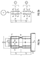
- Fig. 1
- eine schematische Darstellung des Anschlusses von drei Generatorableitungen gemäß der vorliegenden Erfindung in einem Anschlussbereich im Generatorfundament;
- Fig. 2
- eine vergrößerte Darstellung der Einzelheit B von Fig. 1, die den Aufbau eines bevorzugten Ausführungsbeispiels einer erfindungsgemäßen Generatorableitung zeigt;
- Fig. 3a
- und b eine vergrößerte Darstellung des Innenleiters der Generatorableitung von Fig. 2 bzw. ein Ersatzschaltbild davon;
- Fig. 4
- eine schematische Darstellung des Anschlusses von drei herkömmlichen Generatorableitungen in einem Anschlussbereich im Generatorfundament; und
- Fig. 5
- eine vergrößerte Darstellung der Einzelheit E von Fig. 4, die den Aufbau der herkömmlichen Generatorableitung zeigt.
Claims (6)
- Generatorableitung (10) zur elektrischen Verbindung zwischen einem Generator und einem Transformator, mit einem zylindrischen Innenleiter (11) und einem konzentrisch zu dem Innenleiter angeordneten zylindrischen Hüllrohr-Anschlussbereich (12),
dadurch gekennzeichnet, dass der Innenleiter (11) ein inneres Leiterrohr (11a) und ein äußeres Leiterrohr (11b) aufweist, und
dass die Strombahnen in Längsrichtung des Innenleiters (11) wenigstens einmal zwischen dem äußeren Leiterrohr (11b) und dem inneren Leiterrohr (11a) wechseln. - Generatorableitung nach Anspruch 1, bei der das innere und das äußere Leiterrohr (11a, 11b) aus Aluminium gefertigt sind.
- Generatorableitung nach Anspruch 1 oder 2, bei der die Strombahnen in Längsachsenrichtung des Innenleiters (11) einmal an einer Mittelposition in Längsrichtung des Innenleiters zwischen dem äußeren Leiterrohr (11b) und dem inneren Leiterrohr (11a) wechseln.
- Generatorableitung nach einem der Ansprüche 1 bis 3, bei der das innere Leiterrohr (11a) und das äußere Leiterrohr (11b) des Innenleiters (11) konzentrisch angeordnet sind.
- Generatorableitung nach einem der Ansprüche 1 bis 4, bei der zum Wechseln der Strombahnen das innere und das äußere Leiterrohr (11a, 11b) jeweils in Querrichtung getrennt und kreuzweise wieder miteinander verbunden (30) sind.
- Generatorableitung nach einem der Ansprüche 1 bis 5, bei der die Generatorableitung (10) in einem Generator-anschlussbereich im Generatorfundament (14) angeordnet ist.
Priority Applications (3)
| Application Number | Priority Date | Filing Date | Title |
|---|---|---|---|
| ES02023222T ES2713246T3 (es) | 2002-10-16 | 2002-10-16 | Línea de salida de generador, en particular para un área de conexión en la base del generador |
| EP02023222.9A EP1411619B1 (de) | 2002-10-16 | 2002-10-16 | Generatorableitung, insbesondere für einen Anschlussbereich im Generatorfundament |
| US10/685,784 US7019216B2 (en) | 2002-10-16 | 2003-10-16 | Generator output line, in particular for a connection region in the generator base |
Applications Claiming Priority (1)
| Application Number | Priority Date | Filing Date | Title |
|---|---|---|---|
| EP02023222.9A EP1411619B1 (de) | 2002-10-16 | 2002-10-16 | Generatorableitung, insbesondere für einen Anschlussbereich im Generatorfundament |
Publications (2)
| Publication Number | Publication Date |
|---|---|
| EP1411619A1 true EP1411619A1 (de) | 2004-04-21 |
| EP1411619B1 EP1411619B1 (de) | 2018-11-28 |
Family
ID=32039140
Family Applications (1)
| Application Number | Title | Priority Date | Filing Date |
|---|---|---|---|
| EP02023222.9A Expired - Lifetime EP1411619B1 (de) | 2002-10-16 | 2002-10-16 | Generatorableitung, insbesondere für einen Anschlussbereich im Generatorfundament |
Country Status (3)
| Country | Link |
|---|---|
| US (1) | US7019216B2 (de) |
| EP (1) | EP1411619B1 (de) |
| ES (1) | ES2713246T3 (de) |
Cited By (1)
| Publication number | Priority date | Publication date | Assignee | Title |
|---|---|---|---|---|
| EP1903583A1 (de) | 2006-09-25 | 2008-03-26 | Siemens Aktiengesellschaft | Hochstrom-Trafodurchführung |
Families Citing this family (2)
| Publication number | Priority date | Publication date | Assignee | Title |
|---|---|---|---|---|
| WO2014137422A1 (en) | 2013-03-08 | 2014-09-12 | Rolls-Royce North Americantechnologies, Inc. | Aircraft and system for supplying electrical power to an aircraft electrical load |
| EP2922070A1 (de) * | 2014-03-19 | 2015-09-23 | ABB Technology Ltd | Elektrisches Isolierungssystem und elektromagnetische Induktionsvorrichtung damit |
Citations (4)
| Publication number | Priority date | Publication date | Assignee | Title |
|---|---|---|---|---|
| GB443017A (en) * | 1934-07-18 | 1936-02-18 | Harold Smethurst | Improvements in lead-in conductors for transformers, switchgear and like electrical apparatus enclosed in metal casings |
| GB725211A (en) * | 1952-05-16 | 1955-03-02 | Allis Chalmers Mfg Co | Electrical apparatus with fluid cooled terminal bushings |
| US2742582A (en) * | 1953-07-21 | 1956-04-17 | Gen Electric | Gas-cooled high voltage bushing for large generator |
| US4132853A (en) * | 1977-04-25 | 1979-01-02 | Westinghouse Electric Corp. | Electrical bushing |
Family Cites Families (5)
| Publication number | Priority date | Publication date | Assignee | Title |
|---|---|---|---|---|
| US3902000A (en) * | 1974-11-12 | 1975-08-26 | Us Energy | Termination for superconducting power transmission systems |
| US4197571A (en) * | 1975-10-13 | 1980-04-08 | Siemens Aktiengesellschaft | End section for connecting a generator takeoff to a block transformer |
| DE2545832C2 (de) | 1975-10-13 | 1985-01-10 | Siemens AG, 1000 Berlin und 8000 München | Generatorableitung |
| EP0059769B1 (de) * | 1981-03-07 | 1985-10-09 | Kernforschungszentrum Karlsruhe Gmbh | Differenzdruckaufnehmer |
| DE19619729A1 (de) | 1996-05-15 | 1997-11-20 | Siemens Ag | Hochspannungsstromdurchführung bei Generatorgehäusen |
-
2002
- 2002-10-16 ES ES02023222T patent/ES2713246T3/es not_active Expired - Lifetime
- 2002-10-16 EP EP02023222.9A patent/EP1411619B1/de not_active Expired - Lifetime
-
2003
- 2003-10-16 US US10/685,784 patent/US7019216B2/en not_active Expired - Lifetime
Patent Citations (4)
| Publication number | Priority date | Publication date | Assignee | Title |
|---|---|---|---|---|
| GB443017A (en) * | 1934-07-18 | 1936-02-18 | Harold Smethurst | Improvements in lead-in conductors for transformers, switchgear and like electrical apparatus enclosed in metal casings |
| GB725211A (en) * | 1952-05-16 | 1955-03-02 | Allis Chalmers Mfg Co | Electrical apparatus with fluid cooled terminal bushings |
| US2742582A (en) * | 1953-07-21 | 1956-04-17 | Gen Electric | Gas-cooled high voltage bushing for large generator |
| US4132853A (en) * | 1977-04-25 | 1979-01-02 | Westinghouse Electric Corp. | Electrical bushing |
Cited By (1)
| Publication number | Priority date | Publication date | Assignee | Title |
|---|---|---|---|---|
| EP1903583A1 (de) | 2006-09-25 | 2008-03-26 | Siemens Aktiengesellschaft | Hochstrom-Trafodurchführung |
Also Published As
| Publication number | Publication date |
|---|---|
| ES2713246T3 (es) | 2019-05-20 |
| US20050056440A1 (en) | 2005-03-17 |
| EP1411619B1 (de) | 2018-11-28 |
| US7019216B2 (en) | 2006-03-28 |
Similar Documents
| Publication | Publication Date | Title |
|---|---|---|
| EP0142678B1 (de) | Halbleiterventil | |
| DE69728972T2 (de) | Transformator/reactor | |
| CH662454A5 (de) | Anordnung zur verbindung zweier schichtkabel im stirnteil der staenderwicklung eines hochspannungsgenerators. | |
| DE3229480A1 (de) | Trockentransformator mit in giessharz eingegossenen wicklungen | |
| EP2256753B1 (de) | Stromleiter für eine Hochstromdurchführung | |
| DE19603215A1 (de) | Sammelschienensystem | |
| EP1411619B1 (de) | Generatorableitung, insbesondere für einen Anschlussbereich im Generatorfundament | |
| EP0424599B1 (de) | Drehbare Hochstromverbindung | |
| DE19607217B4 (de) | Drehbare Stromverbindung | |
| DE102011082046A1 (de) | Transformator und zugehöriges Herstellungsverfahren | |
| DE1020408B (de) | Einrichtung fuer die Kuehlmittelfuehrung in dynamoelektrischen Maschinen | |
| EP0932168B1 (de) | Koaxialtransformator | |
| EP1903583B1 (de) | Hochstrom-Trafodurchführung | |
| DE962904C (de) | Durchfuehrung fuer grosse Stromstaerken, insbesondere fuer Elektrooefen | |
| EP0073423B1 (de) | Verbindungselement für vollfeststoffisolierte Stromleiter | |
| DE2518178C2 (de) | Metallgekapselte, druckgasisolierte Hochspannungsleitung | |
| EP3490074B1 (de) | Anordnung zum kontaktieren eines schirms eines kabels | |
| DE2624325A1 (de) | Hochspannungsdurchfuehrung | |
| DE19819903C2 (de) | Fluidgekühlte, elektrische Stromleitung | |
| DE1003344B (de) | Gasgekuehlte dynamoelektrische Maschine | |
| EP3574510B1 (de) | Elektrische kontaktanordnung | |
| DE19843087A1 (de) | Induktor zur Erzeugung eines elektromagnetischen Wechselfeldes | |
| EP1841031A1 (de) | Hochstrom-Leitungsanordnung und Generatoranlage | |
| DE2707592A1 (de) | Steckverbindung | |
| DE2848442A1 (de) | Stromzufuehrungseinrichtung fuer die rotorwicklung einer elektrischen maschine |
Legal Events
| Date | Code | Title | Description |
|---|---|---|---|
| PUAI | Public reference made under article 153(3) epc to a published international application that has entered the european phase |
Free format text: ORIGINAL CODE: 0009012 |
|
| AK | Designated contracting states |
Kind code of ref document: A1 Designated state(s): AT BE BG CH CY CZ DE DK EE ES FI FR GB GR IE IT LI LU MC NL PT SE SK TR |
|
| AX | Request for extension of the european patent |
Extension state: AL LT LV MK RO SI |
|
| 17P | Request for examination filed |
Effective date: 20040504 |
|
| AKX | Designation fees paid |
Designated state(s): AT BE BG CH CY CZ DE DK EE ES FI FR GB GR IE IT LI LU MC NL PT SE SK TR |
|
| RAP1 | Party data changed (applicant data changed or rights of an application transferred) |
Owner name: SIEMENS AKTIENGESELLSCHAFT |
|
| RAP1 | Party data changed (applicant data changed or rights of an application transferred) |
Owner name: SIEMENS AKTIENGESELLSCHAFT |
|
| RAP1 | Party data changed (applicant data changed or rights of an application transferred) |
Owner name: SIEMENS AKTIENGESELLSCHAFT |
|
| STAA | Information on the status of an ep patent application or granted ep patent |
Free format text: STATUS: EXAMINATION IS IN PROGRESS |
|
| 17Q | First examination report despatched |
Effective date: 20180516 |
|
| GRAP | Despatch of communication of intention to grant a patent |
Free format text: ORIGINAL CODE: EPIDOSNIGR1 |
|
| STAA | Information on the status of an ep patent application or granted ep patent |
Free format text: STATUS: GRANT OF PATENT IS INTENDED |
|
| INTG | Intention to grant announced |
Effective date: 20180720 |
|
| GRAS | Grant fee paid |
Free format text: ORIGINAL CODE: EPIDOSNIGR3 |
|
| GRAA | (expected) grant |
Free format text: ORIGINAL CODE: 0009210 |
|
| STAA | Information on the status of an ep patent application or granted ep patent |
Free format text: STATUS: THE PATENT HAS BEEN GRANTED |
|
| REG | Reference to a national code |
Ref country code: DE Ref legal event code: R081 Ref document number: 50216318 Country of ref document: DE Owner name: SIEMENS ENERGY GLOBAL GMBH & CO. KG, DE Free format text: FORMER OWNER: SIEMENS AKTIENGESELLSCHAFT, 80333 MUENCHEN, DE |
|
| AK | Designated contracting states |
Kind code of ref document: B1 Designated state(s): AT BE BG CH CY CZ DE DK EE ES FI FR GB GR IE IT LI LU MC NL PT SE SK TR |
|
| REG | Reference to a national code |
Ref country code: GB Ref legal event code: FG4D Free format text: NOT ENGLISH |
|
| REG | Reference to a national code |
Ref country code: CH Ref legal event code: EP |
|
| REG | Reference to a national code |
Ref country code: DE Ref legal event code: R096 Ref document number: 50216318 Country of ref document: DE |
|
| REG | Reference to a national code |
Ref country code: AT Ref legal event code: REF Ref document number: 1071392 Country of ref document: AT Kind code of ref document: T Effective date: 20181215 |
|
| REG | Reference to a national code |
Ref country code: IE Ref legal event code: FG4D Free format text: LANGUAGE OF EP DOCUMENT: GERMAN |
|
| REG | Reference to a national code |
Ref country code: CH Ref legal event code: PK Free format text: BERICHTIGUNGEN |
|
| RIC2 | Information provided on ipc code assigned after grant |
Ipc: H02K 5/22 20060101AFI20030321BHEP Ipc: H01F 27/04 20060101ALI20030321BHEP |
|
| REG | Reference to a national code |
Ref country code: NL Ref legal event code: MP Effective date: 20181128 |
|
| PG25 | Lapsed in a contracting state [announced via postgrant information from national office to epo] |
Ref country code: FI Free format text: LAPSE BECAUSE OF FAILURE TO SUBMIT A TRANSLATION OF THE DESCRIPTION OR TO PAY THE FEE WITHIN THE PRESCRIBED TIME-LIMIT Effective date: 20181128 Ref country code: BG Free format text: LAPSE BECAUSE OF FAILURE TO SUBMIT A TRANSLATION OF THE DESCRIPTION OR TO PAY THE FEE WITHIN THE PRESCRIBED TIME-LIMIT Effective date: 20190228 |
|
| REG | Reference to a national code |
Ref country code: ES Ref legal event code: FG2A Ref document number: 2713246 Country of ref document: ES Kind code of ref document: T3 Effective date: 20190520 |
|
| PG25 | Lapsed in a contracting state [announced via postgrant information from national office to epo] |
Ref country code: PT Free format text: LAPSE BECAUSE OF FAILURE TO SUBMIT A TRANSLATION OF THE DESCRIPTION OR TO PAY THE FEE WITHIN THE PRESCRIBED TIME-LIMIT Effective date: 20190328 Ref country code: SE Free format text: LAPSE BECAUSE OF FAILURE TO SUBMIT A TRANSLATION OF THE DESCRIPTION OR TO PAY THE FEE WITHIN THE PRESCRIBED TIME-LIMIT Effective date: 20181128 Ref country code: GR Free format text: LAPSE BECAUSE OF FAILURE TO SUBMIT A TRANSLATION OF THE DESCRIPTION OR TO PAY THE FEE WITHIN THE PRESCRIBED TIME-LIMIT Effective date: 20190301 |
|
| PG25 | Lapsed in a contracting state [announced via postgrant information from national office to epo] |
Ref country code: NL Free format text: LAPSE BECAUSE OF FAILURE TO SUBMIT A TRANSLATION OF THE DESCRIPTION OR TO PAY THE FEE WITHIN THE PRESCRIBED TIME-LIMIT Effective date: 20181128 |
|
| PG25 | Lapsed in a contracting state [announced via postgrant information from national office to epo] |
Ref country code: CZ Free format text: LAPSE BECAUSE OF FAILURE TO SUBMIT A TRANSLATION OF THE DESCRIPTION OR TO PAY THE FEE WITHIN THE PRESCRIBED TIME-LIMIT Effective date: 20181128 Ref country code: DK Free format text: LAPSE BECAUSE OF FAILURE TO SUBMIT A TRANSLATION OF THE DESCRIPTION OR TO PAY THE FEE WITHIN THE PRESCRIBED TIME-LIMIT Effective date: 20181128 |
|
| REG | Reference to a national code |
Ref country code: DE Ref legal event code: R097 Ref document number: 50216318 Country of ref document: DE |
|
| PG25 | Lapsed in a contracting state [announced via postgrant information from national office to epo] |
Ref country code: EE Free format text: LAPSE BECAUSE OF FAILURE TO SUBMIT A TRANSLATION OF THE DESCRIPTION OR TO PAY THE FEE WITHIN THE PRESCRIBED TIME-LIMIT Effective date: 20181128 Ref country code: SK Free format text: LAPSE BECAUSE OF FAILURE TO SUBMIT A TRANSLATION OF THE DESCRIPTION OR TO PAY THE FEE WITHIN THE PRESCRIBED TIME-LIMIT Effective date: 20181128 |
|
| PLBE | No opposition filed within time limit |
Free format text: ORIGINAL CODE: 0009261 |
|
| STAA | Information on the status of an ep patent application or granted ep patent |
Free format text: STATUS: NO OPPOSITION FILED WITHIN TIME LIMIT |
|
| 26N | No opposition filed |
Effective date: 20190829 |
|
| PG25 | Lapsed in a contracting state [announced via postgrant information from national office to epo] |
Ref country code: TR Free format text: LAPSE BECAUSE OF FAILURE TO SUBMIT A TRANSLATION OF THE DESCRIPTION OR TO PAY THE FEE WITHIN THE PRESCRIBED TIME-LIMIT Effective date: 20181128 |
|
| PG25 | Lapsed in a contracting state [announced via postgrant information from national office to epo] |
Ref country code: MC Free format text: LAPSE BECAUSE OF FAILURE TO SUBMIT A TRANSLATION OF THE DESCRIPTION OR TO PAY THE FEE WITHIN THE PRESCRIBED TIME-LIMIT Effective date: 20181128 |
|
| REG | Reference to a national code |
Ref country code: CH Ref legal event code: PL |
|
| PG25 | Lapsed in a contracting state [announced via postgrant information from national office to epo] |
Ref country code: LI Free format text: LAPSE BECAUSE OF NON-PAYMENT OF DUE FEES Effective date: 20191031 Ref country code: CH Free format text: LAPSE BECAUSE OF NON-PAYMENT OF DUE FEES Effective date: 20191031 Ref country code: LU Free format text: LAPSE BECAUSE OF NON-PAYMENT OF DUE FEES Effective date: 20191016 |
|
| REG | Reference to a national code |
Ref country code: BE Ref legal event code: MM Effective date: 20191031 |
|
| PG25 | Lapsed in a contracting state [announced via postgrant information from national office to epo] |
Ref country code: BE Free format text: LAPSE BECAUSE OF NON-PAYMENT OF DUE FEES Effective date: 20191031 |
|
| PG25 | Lapsed in a contracting state [announced via postgrant information from national office to epo] |
Ref country code: IE Free format text: LAPSE BECAUSE OF NON-PAYMENT OF DUE FEES Effective date: 20191016 |
|
| REG | Reference to a national code |
Ref country code: AT Ref legal event code: MM01 Ref document number: 1071392 Country of ref document: AT Kind code of ref document: T Effective date: 20191016 Ref country code: DE Ref legal event code: R081 Ref document number: 50216318 Country of ref document: DE Owner name: SIEMENS ENERGY GLOBAL GMBH & CO. KG, DE Free format text: FORMER OWNER: SIEMENS AKTIENGESELLSCHAFT, 80333 MUENCHEN, DE |
|
| PG25 | Lapsed in a contracting state [announced via postgrant information from national office to epo] |
Ref country code: AT Free format text: LAPSE BECAUSE OF NON-PAYMENT OF DUE FEES Effective date: 20191016 |
|
| PG25 | Lapsed in a contracting state [announced via postgrant information from national office to epo] |
Ref country code: CY Free format text: LAPSE BECAUSE OF FAILURE TO SUBMIT A TRANSLATION OF THE DESCRIPTION OR TO PAY THE FEE WITHIN THE PRESCRIBED TIME-LIMIT Effective date: 20181128 |
|
| PGFP | Annual fee paid to national office [announced via postgrant information from national office to epo] |
Ref country code: DE Payment date: 20211224 Year of fee payment: 20 Ref country code: GB Payment date: 20211118 Year of fee payment: 20 |
|
| PGFP | Annual fee paid to national office [announced via postgrant information from national office to epo] |
Ref country code: IT Payment date: 20211022 Year of fee payment: 20 Ref country code: FR Payment date: 20211020 Year of fee payment: 20 |
|
| PGFP | Annual fee paid to national office [announced via postgrant information from national office to epo] |
Ref country code: ES Payment date: 20220125 Year of fee payment: 20 |
|
| REG | Reference to a national code |
Ref country code: GB Ref legal event code: 732E Free format text: REGISTERED BETWEEN 20220811 AND 20220817 |
|
| REG | Reference to a national code |
Ref country code: DE Ref legal event code: R071 Ref document number: 50216318 Country of ref document: DE |
|
| REG | Reference to a national code |
Ref country code: ES Ref legal event code: FD2A Effective date: 20221031 |
|
| REG | Reference to a national code |
Ref country code: GB Ref legal event code: PE20 Expiry date: 20221015 |
|
| PG25 | Lapsed in a contracting state [announced via postgrant information from national office to epo] |
Ref country code: GB Free format text: LAPSE BECAUSE OF EXPIRATION OF PROTECTION Effective date: 20221015 Ref country code: ES Free format text: LAPSE BECAUSE OF EXPIRATION OF PROTECTION Effective date: 20221017 |