EP1411313B1 - Kühlverfahren und -vorrichtung mit Phasenumwandlungsmaterial enthaltenden Wärmeaustauschelementen - Google Patents
Kühlverfahren und -vorrichtung mit Phasenumwandlungsmaterial enthaltenden Wärmeaustauschelementen Download PDFInfo
- Publication number
- EP1411313B1 EP1411313B1 EP03394097A EP03394097A EP1411313B1 EP 1411313 B1 EP1411313 B1 EP 1411313B1 EP 03394097 A EP03394097 A EP 03394097A EP 03394097 A EP03394097 A EP 03394097A EP 1411313 B1 EP1411313 B1 EP 1411313B1
- Authority
- EP
- European Patent Office
- Prior art keywords
- heat
- liquid
- heat transfer
- containers
- pan
- Prior art date
- Legal status (The legal status is an assumption and is not a legal conclusion. Google has not performed a legal analysis and makes no representation as to the accuracy of the status listed.)
- Expired - Lifetime
Links
Images


Classifications
-
- A—HUMAN NECESSITIES
- A61—MEDICAL OR VETERINARY SCIENCE; HYGIENE
- A61F—FILTERS IMPLANTABLE INTO BLOOD VESSELS; PROSTHESES; DEVICES PROVIDING PATENCY TO, OR PREVENTING COLLAPSING OF, TUBULAR STRUCTURES OF THE BODY, e.g. STENTS; ORTHOPAEDIC, NURSING OR CONTRACEPTIVE DEVICES; FOMENTATION; TREATMENT OR PROTECTION OF EYES OR EARS; BANDAGES, DRESSINGS OR ABSORBENT PADS; FIRST-AID KITS
- A61F7/00—Heating or cooling appliances for medical or therapeutic treatment of the human body
- A61F7/02—Compresses or poultices for effecting heating or cooling
-
- B—PERFORMING OPERATIONS; TRANSPORTING
- B29—WORKING OF PLASTICS; WORKING OF SUBSTANCES IN A PLASTIC STATE IN GENERAL
- B29C—SHAPING OR JOINING OF PLASTICS; SHAPING OF MATERIAL IN A PLASTIC STATE, NOT OTHERWISE PROVIDED FOR; AFTER-TREATMENT OF THE SHAPED PRODUCTS, e.g. REPAIRING
- B29C66/00—General aspects of processes or apparatus for joining preformed parts
- B29C66/01—General aspects dealing with the joint area or with the area to be joined
- B29C66/05—Particular design of joint configurations
- B29C66/10—Particular design of joint configurations particular design of the joint cross-sections
- B29C66/11—Joint cross-sections comprising a single joint-segment, i.e. one of the parts to be joined comprising a single joint-segment in the joint cross-section
- B29C66/112—Single lapped joints
-
- B—PERFORMING OPERATIONS; TRANSPORTING
- B29—WORKING OF PLASTICS; WORKING OF SUBSTANCES IN A PLASTIC STATE IN GENERAL
- B29C—SHAPING OR JOINING OF PLASTICS; SHAPING OF MATERIAL IN A PLASTIC STATE, NOT OTHERWISE PROVIDED FOR; AFTER-TREATMENT OF THE SHAPED PRODUCTS, e.g. REPAIRING
- B29C66/00—General aspects of processes or apparatus for joining preformed parts
- B29C66/01—General aspects dealing with the joint area or with the area to be joined
- B29C66/05—Particular design of joint configurations
- B29C66/10—Particular design of joint configurations particular design of the joint cross-sections
- B29C66/13—Single flanged joints; Fin-type joints; Single hem joints; Edge joints; Interpenetrating fingered joints; Other specific particular designs of joint cross-sections not provided for in groups B29C66/11 - B29C66/12
- B29C66/131—Single flanged joints, i.e. one of the parts to be joined being rigid and flanged in the joint area
- B29C66/1312—Single flange to flange joints, the parts to be joined being rigid
-
- B—PERFORMING OPERATIONS; TRANSPORTING
- B29—WORKING OF PLASTICS; WORKING OF SUBSTANCES IN A PLASTIC STATE IN GENERAL
- B29C—SHAPING OR JOINING OF PLASTICS; SHAPING OF MATERIAL IN A PLASTIC STATE, NOT OTHERWISE PROVIDED FOR; AFTER-TREATMENT OF THE SHAPED PRODUCTS, e.g. REPAIRING
- B29C66/00—General aspects of processes or apparatus for joining preformed parts
- B29C66/50—General aspects of joining tubular articles; General aspects of joining long products, i.e. bars or profiled elements; General aspects of joining single elements to tubular articles, hollow articles or bars; General aspects of joining several hollow-preforms to form hollow or tubular articles
- B29C66/51—Joining tubular articles, profiled elements or bars; Joining single elements to tubular articles, hollow articles or bars; Joining several hollow-preforms to form hollow or tubular articles
- B29C66/53—Joining single elements to tubular articles, hollow articles or bars
- B29C66/534—Joining single elements to open ends of tubular or hollow articles or to the ends of bars
- B29C66/5346—Joining single elements to open ends of tubular or hollow articles or to the ends of bars said single elements being substantially flat
- B29C66/53461—Joining single elements to open ends of tubular or hollow articles or to the ends of bars said single elements being substantially flat joining substantially flat covers and/or substantially flat bottoms to open ends of container bodies
-
- B—PERFORMING OPERATIONS; TRANSPORTING
- B32—LAYERED PRODUCTS
- B32B—LAYERED PRODUCTS, i.e. PRODUCTS BUILT-UP OF STRATA OF FLAT OR NON-FLAT, e.g. CELLULAR OR HONEYCOMB, FORM
- B32B3/00—Layered products comprising a layer with external or internal discontinuities or unevennesses, or a layer of non-planar shape; Layered products comprising a layer having particular features of form
- B32B3/26—Layered products comprising a layer with external or internal discontinuities or unevennesses, or a layer of non-planar shape; Layered products comprising a layer having particular features of form characterised by a particular shape of the outline of the cross-section of a continuous layer; characterised by a layer with cavities or internal voids ; characterised by an apertured layer
- B32B3/28—Layered products comprising a layer with external or internal discontinuities or unevennesses, or a layer of non-planar shape; Layered products comprising a layer having particular features of form characterised by a particular shape of the outline of the cross-section of a continuous layer; characterised by a layer with cavities or internal voids ; characterised by an apertured layer characterised by a layer comprising a deformed thin sheet, i.e. the layer having its entire thickness deformed out of the plane, e.g. corrugated, crumpled
-
- F—MECHANICAL ENGINEERING; LIGHTING; HEATING; WEAPONS; BLASTING
- F25—REFRIGERATION OR COOLING; COMBINED HEATING AND REFRIGERATION SYSTEMS; HEAT PUMP SYSTEMS; MANUFACTURE OR STORAGE OF ICE; LIQUEFACTION SOLIDIFICATION OF GASES
- F25D—REFRIGERATORS; COLD ROOMS; ICE-BOXES; COOLING OR FREEZING APPARATUS NOT OTHERWISE PROVIDED FOR
- F25D3/00—Devices using other cold materials; Devices using cold-storage bodies
- F25D3/02—Devices using other cold materials; Devices using cold-storage bodies using ice, e.g. ice-boxes
- F25D3/06—Movable containers
- F25D3/08—Movable containers portable, i.e. adapted to be carried personally
-
- F—MECHANICAL ENGINEERING; LIGHTING; HEATING; WEAPONS; BLASTING
- F28—HEAT EXCHANGE IN GENERAL
- F28D—HEAT-EXCHANGE APPARATUS, NOT PROVIDED FOR IN ANOTHER SUBCLASS, IN WHICH THE HEAT-EXCHANGE MEDIA DO NOT COME INTO DIRECT CONTACT
- F28D20/00—Heat storage plants or apparatus in general; Regenerative heat-exchange apparatus not covered by groups F28D17/00 or F28D19/00
- F28D20/02—Heat storage plants or apparatus in general; Regenerative heat-exchange apparatus not covered by groups F28D17/00 or F28D19/00 using latent heat
- F28D20/023—Heat storage plants or apparatus in general; Regenerative heat-exchange apparatus not covered by groups F28D17/00 or F28D19/00 using latent heat the latent heat storage material being enclosed in granular particles or dispersed in a porous, fibrous or cellular structure
-
- F—MECHANICAL ENGINEERING; LIGHTING; HEATING; WEAPONS; BLASTING
- F28—HEAT EXCHANGE IN GENERAL
- F28D—HEAT-EXCHANGE APPARATUS, NOT PROVIDED FOR IN ANOTHER SUBCLASS, IN WHICH THE HEAT-EXCHANGE MEDIA DO NOT COME INTO DIRECT CONTACT
- F28D20/00—Heat storage plants or apparatus in general; Regenerative heat-exchange apparatus not covered by groups F28D17/00 or F28D19/00
- F28D20/02—Heat storage plants or apparatus in general; Regenerative heat-exchange apparatus not covered by groups F28D17/00 or F28D19/00 using latent heat
- F28D20/026—Heat storage plants or apparatus in general; Regenerative heat-exchange apparatus not covered by groups F28D17/00 or F28D19/00 using latent heat with different heat storage materials not coming into direct contact
-
- A—HUMAN NECESSITIES
- A61—MEDICAL OR VETERINARY SCIENCE; HYGIENE
- A61F—FILTERS IMPLANTABLE INTO BLOOD VESSELS; PROSTHESES; DEVICES PROVIDING PATENCY TO, OR PREVENTING COLLAPSING OF, TUBULAR STRUCTURES OF THE BODY, e.g. STENTS; ORTHOPAEDIC, NURSING OR CONTRACEPTIVE DEVICES; FOMENTATION; TREATMENT OR PROTECTION OF EYES OR EARS; BANDAGES, DRESSINGS OR ABSORBENT PADS; FIRST-AID KITS
- A61F7/00—Heating or cooling appliances for medical or therapeutic treatment of the human body
- A61F2007/0098—Heating or cooling appliances for medical or therapeutic treatment of the human body ways of manufacturing heating or cooling devices for therapy
-
- A—HUMAN NECESSITIES
- A61—MEDICAL OR VETERINARY SCIENCE; HYGIENE
- A61F—FILTERS IMPLANTABLE INTO BLOOD VESSELS; PROSTHESES; DEVICES PROVIDING PATENCY TO, OR PREVENTING COLLAPSING OF, TUBULAR STRUCTURES OF THE BODY, e.g. STENTS; ORTHOPAEDIC, NURSING OR CONTRACEPTIVE DEVICES; FOMENTATION; TREATMENT OR PROTECTION OF EYES OR EARS; BANDAGES, DRESSINGS OR ABSORBENT PADS; FIRST-AID KITS
- A61F7/00—Heating or cooling appliances for medical or therapeutic treatment of the human body
- A61F7/02—Compresses or poultices for effecting heating or cooling
- A61F2007/0268—Compresses or poultices for effecting heating or cooling having a plurality of compartments being filled with a heat carrier
-
- A—HUMAN NECESSITIES
- A61—MEDICAL OR VETERINARY SCIENCE; HYGIENE
- A61F—FILTERS IMPLANTABLE INTO BLOOD VESSELS; PROSTHESES; DEVICES PROVIDING PATENCY TO, OR PREVENTING COLLAPSING OF, TUBULAR STRUCTURES OF THE BODY, e.g. STENTS; ORTHOPAEDIC, NURSING OR CONTRACEPTIVE DEVICES; FOMENTATION; TREATMENT OR PROTECTION OF EYES OR EARS; BANDAGES, DRESSINGS OR ABSORBENT PADS; FIRST-AID KITS
- A61F7/00—Heating or cooling appliances for medical or therapeutic treatment of the human body
- A61F7/02—Compresses or poultices for effecting heating or cooling
- A61F2007/0292—Compresses or poultices for effecting heating or cooling using latent heat produced or absorbed during phase change of materials, e.g. of super-cooled solutions
-
- B—PERFORMING OPERATIONS; TRANSPORTING
- B29—WORKING OF PLASTICS; WORKING OF SUBSTANCES IN A PLASTIC STATE IN GENERAL
- B29C—SHAPING OR JOINING OF PLASTICS; SHAPING OF MATERIAL IN A PLASTIC STATE, NOT OTHERWISE PROVIDED FOR; AFTER-TREATMENT OF THE SHAPED PRODUCTS, e.g. REPAIRING
- B29C51/00—Shaping by thermoforming, i.e. shaping sheets or sheet like preforms after heating, e.g. shaping sheets in matched moulds or by deep-drawing; Apparatus therefor
- B29C51/08—Deep drawing or matched-mould forming, i.e. using mechanical means only
-
- B—PERFORMING OPERATIONS; TRANSPORTING
- B29—WORKING OF PLASTICS; WORKING OF SUBSTANCES IN A PLASTIC STATE IN GENERAL
- B29C—SHAPING OR JOINING OF PLASTICS; SHAPING OF MATERIAL IN A PLASTIC STATE, NOT OTHERWISE PROVIDED FOR; AFTER-TREATMENT OF THE SHAPED PRODUCTS, e.g. REPAIRING
- B29C66/00—General aspects of processes or apparatus for joining preformed parts
- B29C66/70—General aspects of processes or apparatus for joining preformed parts characterised by the composition, physical properties or the structure of the material of the parts to be joined; Joining with non-plastics material
- B29C66/71—General aspects of processes or apparatus for joining preformed parts characterised by the composition, physical properties or the structure of the material of the parts to be joined; Joining with non-plastics material characterised by the composition of the plastics material of the parts to be joined
-
- B—PERFORMING OPERATIONS; TRANSPORTING
- B29—WORKING OF PLASTICS; WORKING OF SUBSTANCES IN A PLASTIC STATE IN GENERAL
- B29C—SHAPING OR JOINING OF PLASTICS; SHAPING OF MATERIAL IN A PLASTIC STATE, NOT OTHERWISE PROVIDED FOR; AFTER-TREATMENT OF THE SHAPED PRODUCTS, e.g. REPAIRING
- B29C66/00—General aspects of processes or apparatus for joining preformed parts
- B29C66/70—General aspects of processes or apparatus for joining preformed parts characterised by the composition, physical properties or the structure of the material of the parts to be joined; Joining with non-plastics material
- B29C66/72—General aspects of processes or apparatus for joining preformed parts characterised by the composition, physical properties or the structure of the material of the parts to be joined; Joining with non-plastics material characterised by the structure of the material of the parts to be joined
- B29C66/723—General aspects of processes or apparatus for joining preformed parts characterised by the composition, physical properties or the structure of the material of the parts to be joined; Joining with non-plastics material characterised by the structure of the material of the parts to be joined being multi-layered
- B29C66/7234—General aspects of processes or apparatus for joining preformed parts characterised by the composition, physical properties or the structure of the material of the parts to be joined; Joining with non-plastics material characterised by the structure of the material of the parts to be joined being multi-layered comprising a barrier layer
- B29C66/72343—General aspects of processes or apparatus for joining preformed parts characterised by the composition, physical properties or the structure of the material of the parts to be joined; Joining with non-plastics material characterised by the structure of the material of the parts to be joined being multi-layered comprising a barrier layer for liquids
-
- B—PERFORMING OPERATIONS; TRANSPORTING
- B29—WORKING OF PLASTICS; WORKING OF SUBSTANCES IN A PLASTIC STATE IN GENERAL
- B29L—INDEXING SCHEME ASSOCIATED WITH SUBCLASS B29C, RELATING TO PARTICULAR ARTICLES
- B29L2022/00—Hollow articles
- B29L2022/005—Hollow articles having dividing walls, e.g. additional elements placed between object parts
-
- B—PERFORMING OPERATIONS; TRANSPORTING
- B29—WORKING OF PLASTICS; WORKING OF SUBSTANCES IN A PLASTIC STATE IN GENERAL
- B29L—INDEXING SCHEME ASSOCIATED WITH SUBCLASS B29C, RELATING TO PARTICULAR ARTICLES
- B29L2022/00—Hollow articles
- B29L2022/02—Inflatable articles
-
- B—PERFORMING OPERATIONS; TRANSPORTING
- B29—WORKING OF PLASTICS; WORKING OF SUBSTANCES IN A PLASTIC STATE IN GENERAL
- B29L—INDEXING SCHEME ASSOCIATED WITH SUBCLASS B29C, RELATING TO PARTICULAR ARTICLES
- B29L2031/00—Other particular articles
- B29L2031/18—Heat-exchangers or parts thereof
-
- F—MECHANICAL ENGINEERING; LIGHTING; HEATING; WEAPONS; BLASTING
- F25—REFRIGERATION OR COOLING; COMBINED HEATING AND REFRIGERATION SYSTEMS; HEAT PUMP SYSTEMS; MANUFACTURE OR STORAGE OF ICE; LIQUEFACTION SOLIDIFICATION OF GASES
- F25D—REFRIGERATORS; COLD ROOMS; ICE-BOXES; COOLING OR FREEZING APPARATUS NOT OTHERWISE PROVIDED FOR
- F25D2303/00—Details of devices using other cold materials; Details of devices using cold-storage bodies
- F25D2303/08—Devices using cold storage material, i.e. ice or other freezable liquid
- F25D2303/082—Devices using cold storage material, i.e. ice or other freezable liquid disposed in a cold storage element not forming part of a container for products to be cooled, e.g. ice pack or gel accumulator
-
- F—MECHANICAL ENGINEERING; LIGHTING; HEATING; WEAPONS; BLASTING
- F25—REFRIGERATION OR COOLING; COMBINED HEATING AND REFRIGERATION SYSTEMS; HEAT PUMP SYSTEMS; MANUFACTURE OR STORAGE OF ICE; LIQUEFACTION SOLIDIFICATION OF GASES
- F25D—REFRIGERATORS; COLD ROOMS; ICE-BOXES; COOLING OR FREEZING APPARATUS NOT OTHERWISE PROVIDED FOR
- F25D2303/00—Details of devices using other cold materials; Details of devices using cold-storage bodies
- F25D2303/08—Devices using cold storage material, i.e. ice or other freezable liquid
- F25D2303/085—Compositions of cold storage materials
-
- F—MECHANICAL ENGINEERING; LIGHTING; HEATING; WEAPONS; BLASTING
- F25—REFRIGERATION OR COOLING; COMBINED HEATING AND REFRIGERATION SYSTEMS; HEAT PUMP SYSTEMS; MANUFACTURE OR STORAGE OF ICE; LIQUEFACTION SOLIDIFICATION OF GASES
- F25D—REFRIGERATORS; COLD ROOMS; ICE-BOXES; COOLING OR FREEZING APPARATUS NOT OTHERWISE PROVIDED FOR
- F25D2331/00—Details or arrangements of other cooling or freezing apparatus not provided for in other groups of this subclass
- F25D2331/80—Type of cooled receptacles
- F25D2331/804—Boxes
-
- F—MECHANICAL ENGINEERING; LIGHTING; HEATING; WEAPONS; BLASTING
- F25—REFRIGERATION OR COOLING; COMBINED HEATING AND REFRIGERATION SYSTEMS; HEAT PUMP SYSTEMS; MANUFACTURE OR STORAGE OF ICE; LIQUEFACTION SOLIDIFICATION OF GASES
- F25D—REFRIGERATORS; COLD ROOMS; ICE-BOXES; COOLING OR FREEZING APPARATUS NOT OTHERWISE PROVIDED FOR
- F25D2500/00—Problems to be solved
- F25D2500/02—Geometry problems
-
- F—MECHANICAL ENGINEERING; LIGHTING; HEATING; WEAPONS; BLASTING
- F28—HEAT EXCHANGE IN GENERAL
- F28D—HEAT-EXCHANGE APPARATUS, NOT PROVIDED FOR IN ANOTHER SUBCLASS, IN WHICH THE HEAT-EXCHANGE MEDIA DO NOT COME INTO DIRECT CONTACT
- F28D20/00—Heat storage plants or apparatus in general; Regenerative heat-exchange apparatus not covered by groups F28D17/00 or F28D19/00
- F28D2020/0004—Particular heat storage apparatus
- F28D2020/0008—Particular heat storage apparatus the heat storage material being enclosed in plate-like or laminated elements, e.g. in plates having internal compartments
-
- Y—GENERAL TAGGING OF NEW TECHNOLOGICAL DEVELOPMENTS; GENERAL TAGGING OF CROSS-SECTIONAL TECHNOLOGIES SPANNING OVER SEVERAL SECTIONS OF THE IPC; TECHNICAL SUBJECTS COVERED BY FORMER USPC CROSS-REFERENCE ART COLLECTIONS [XRACs] AND DIGESTS
- Y02—TECHNOLOGIES OR APPLICATIONS FOR MITIGATION OR ADAPTATION AGAINST CLIMATE CHANGE
- Y02E—REDUCTION OF GREENHOUSE GAS [GHG] EMISSIONS, RELATED TO ENERGY GENERATION, TRANSMISSION OR DISTRIBUTION
- Y02E60/00—Enabling technologies; Technologies with a potential or indirect contribution to GHG emissions mitigation
- Y02E60/14—Thermal energy storage
Definitions
- This invention pertains to apparatus and methods for abstracting heat from an individual's neck or other part of the body.
- United States Patent Specification No. US 2002/0148249 discloses an apparatus for abstracting heat comprising a container charged with a first liquid and with small auxiliary containers free to circulate in the first liquid. Each of the small auxiliary containers is charged with a second liquid. The freezing point of the first liquid is less than the second liquid such that when the second liquid is frozen, the first liquid is not, is free to circulate, and permits the auxiliary containers to circulate in the first liquid.
- DE 44 15 946 A discloses a flexible cool packing for keeping body part cool, comprising spherical or cylindrical hollow chambers containing a coolant.
- the present invention pertains to an improved apparatus and method which utilizes a matrix comprised of liquids and solids to abstract, over an extended period of time, heat from an individual's neck or other part of the body.
- the invention pertains to an improved apparatus of the type described which utilizes a plurality of heat transfer elements having three dimensional parity.
- the invention pertains to an improved heat abstracting apparatus of the type described which convects heat along paths intermediate spaced apart heat transfer elements.
- the invention pertains to an improved apparatus and method of the type described in which heat transfer elements are shaped to absorb heat along vertical and lateral paths.
- the invention pertains to an improved simplified method of manufacturing a heat transfer device.
- the invention pertains to an improved heat abstracting apparatus of the type described which provides efficient transfer using a single heat transfer element - liquid interface.
- cold packs are well known and typically, for example, comprise pliable, hollow, vinyl containers filled with a gelatin. In use, the cold pack is frozen and is placed against an individual's neck or other part of the individual's body to cool the individual.
- One such conventional cold pack is marketed under the trademark "THERAPAC” and comprises a 30cm by 30cm (twelve inch-by- twelve inch) two ply vinyl container filled with a white odorless insoluble gelatin.
- Another conventional cold pack is marketed under the trademark "COLPAC” and comprises a 30cm by 30cm (twelve inch-by-tweive inch) single ply polymer container filled with a grey odorless soluble gelatin.
- Such conventional cold packs are widely disseminated and effectively absorb heat.
- One principal disadvantage of such cold packs is that they have a relatively short-lived ability to stay cold.
- the temperature on the outer surface of the cold pack can be -15.00°C (five degrees F). After about an hour, the temperature can be about 7.22 to 10°C (forty five to fifty degrees F). After about two hours, the temperature on the outer surface of the cold packs can be about 11.11 to 14.44°C (fifty-two to fifty-eight degrees F). After about three hours, the temperature can be about 18.33 to 21.11°C (sixty-five to seventy degrees F). Consequently, after only an hour, the temperature of the outer surface of each of the cold packs is well above freezing.
- a further object of the instant invention is to provide an improved cold pack which will maintain a cold temperature for an extended period of time after being exposed to a temperature greater than that of the cold pack.
- Another object of the invention is to provide an improved method for manufacturing a cold pack.
- Still a further object of the invention is to provide a heat transfer device that facilitates conforming the device to the contour of the body.
- Still another object of the invention is to provide an improved heat transfer device with a module matrix that facilitates folding the device and partitioning the device.
- I provide an improved heat transfer device for use in contacting and drawing heat away from an individual's neck or other part of the body.
- I provide an improved pliable two phase single wall heat transfer device for use in contacting and drawing heat away from an individual's neck or other part of the body.
- the heat transfer device comprises an outer wall circumscribing and enclosing an inner space; a plurality of spaced apart hollow fluid tight containers connected to a portion of the wall, extending from the wail into the inner space, wherein each of the containers is cylindrically shaped and has dimensional parity and the cylindrical containers have rounded bottoms that contact the outer wall, a first heat-exchange composition in the inner space contacting each of the fluid tight containers and comprising a liquid which undergoes a change of state from the liquid phase to the solid phase at a selected temperature of transformation; and, a second heat-exchange composition in each of the hollow containers comprising a liquid which undergoes a change of state from the liquid phase to the solid phase at a selected temperature of transformation.
- the device further comprises a plurality of channels interconnecting pairs of the hollow containers to promote the flow of liquid there
- I provide an improved method for manufacturing a two phase single wall bi-directional heat transfer device for use in contacting and drawing heat away from an individual's neck or other part of the body.
- the improved method includes the steps of providing a first sheet of pliable material; forming a pan with the sheet of material the pan including a peripheral lip extending around the pan; charging the pan with a first heat-exchange composition comprising a liquid which undergoes a change of state from the liquid phase to the solid phase at a selected temperature of transformation; providing a second sheet of pliable material; forming a module matrix with the second sheet of material, the module matrix including a peripheral edge and including a plurality of modules each with a bottom and an open top each of the modules being cylindrically shaped and having dimensional parity and the cylindrical modules including rounded bottoms; placing the module matrix in the pan such that said rounded bottom of each module extends into the first heat-exchange composition and contacts said pan; administering a second heat-exchange composition to each of the modules
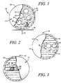
- FIG. 1 illustrates a heat transfer device generally identified by reference character 10.
- Device 10 of Figure 1 represents background art and is not part of the invention as defined in the appended claims.
- Device 10 includes a spherical hollow primary container having a wall 11 including spherical outer surface 12 and spherical inner surface 13, A liquid 14 is housed inside the primary container.
- At least one auxiliary spherical hollow container 15 is in and free to move and circulate about thy reservoir formed by liquid 14.
- Each hollow container 15 includes a spherical wall 30 having a spherical outer surface 16 and a spherical inner surface 17.
- a liquid 18 is housed inside each auxiliary container 15.
- Liquid 14 has a lower (cooler) freezing point than liquid 18, and may have a freezing point lower than the coldest temperatures found in conventional household or commercial freezers.
- liquid 14 presently comprises propylene glycol and liquid 18 comprises water.
- Liquid 18 may have a freezing point greater or equal to the coldest temperature found in conventional household or commercial freezers.
- compositions that can be utilized as liquid 14 or liquid 18 include aqueous solutions of ethyl alcohol, methyl alcohol, PRESTONE, iso-propyl alcohol, and glycerol.
- Magnesium chloride, sodium chloride, and calcium chloride brines can be utilized.
- Refrigerants which can be utilized as liquid 14 include ammonia, ethyl chloride, and methyl chloride.
- the wall 11 can be fabricated from a pliable vinyl or other pliable material so that wall 11 will conform to a part of an individual's body or will conform to some other object that is contacted by heat transfer device 10.
- the wall 30 can be fabricated from a pliable vinyl or other pliable material so that wall 30 will conform to a part of an individual's body or will conform to some other object.
- device 10 and walls 11 and 15 need not be spherical and can be made to have any desired shape, contour, and dimension. Walls 11 and 15 need not be pliable and can be substantially rigid.
- device 10 In use of the heat transfer device 10, device 10 is placed in a freezer. Liquid 18, being water, freezes. Liquid 14, being propylene glycol, does not freeze. After liquid 18 freezes, device 10 is removed from the freezer and placed against a portion 40 of an individual's body or against some other object or substance so that device 10 absorbs heat H. Heat is absorbed through wall 11 and into liquid 14 by the transfer of kinetic energy from particle to particle. When heat is absorbed by liquid 14, liquid 14 has a non-uniform temperature, i.e., liquid near wall 11 is warmer and has a greater enthalpy than liquid farther away from wall 11. If liquid near wall 11 has a different temperature, the density of the liquid near wall 11 is different than the density of cooler liquid farther away from wall 11.
- This density differential causes circulation and movement of liquid 14.
- warmed liquid 14 passes by and contacts an auxiliary spherical hollow container 15, heat is absorbed through wall 30 and into frozen liquid 18 by the transfer of kinetic energy from particle to particle.
- the heat transfer device of Fig. 2 is identical to that of Fig. 1 except that auxiliary containers 15 are connected in a chain to each other and to the inner surface of wall 13 by links 19, 20, and 21, respectively.
- This chain can be slack so that containers 15 can, to a degree, move about In liquid 14, or, the chain can be substantially rigid so it maintains its shape and dimension even if pliable wall 11 is displaced.
- the heat transfer device of Fig. 3 is identical to that of Fig. 1 except that auxiliary containers 15 are removed and replaced by an elongate hollow auxiliary container 31 having a cylindrical wall 24 with a cylindrical outer surface 25 and a cylindrical inner surface 26.
- Container 31 is filled with a liquid 28 which, like liquid 18, has a freezing point which is greater (warmer) than that of liquid 14.
- liquids 18 and/or 28 have a freezing point which is less than that of liquid 14.
- liquid 14, when frozen, can be malleable or readily broken into pieces which permit a pliable wall 13 to be displaced and manipulated like the pliable rubber wall of a hot water bottle can be manipulated when the water bottle is filled with water
- liquids 18 and/or 28 have a freezing point equivalent to that of liquid 14.
- auxiliary containers 15 absorb heat from liquid 14.
- auxiliary container 31 absorbs heat from liquid 14.
- the ratio of the mass of liquid 14 with respect to the mass of liquid 18 (or 28) in a device 10 can vary as desired, and can be about 1:1. As the mass of liquid 18 with respect to the mass of liquid 14 increases, the heat absorbing capacity of liquid 18 increases, but there is less of liquid 14 to circulate to containers 15 heat which is absorbed from wall 11. It is believed that if the mass of liquid 18 greatly exceeds that of liquid 14 (e.g., the ratio of liquid 18 to liquid 14 is, for example, 8:1), then heat will tend to be absorbed directly by containers 15 instead of first being absorbed by liquid 14 and transferred to containers 15. The use of liquid 14 to circulate heat to containers 15 is believed, at least in part, responsible for why the heat transfer apparatus stays cool for unusually long periods of time.
- the ratio of liquid 18 to liquid 14 may be the range of 3:1 to 1:3, most preferably in the range of 2:1 to 1:2.
- walls 11 and 30 and 24 affect the rate of heat transfer. Thicker walls normally transfer heat at a slower rate; thinner walls at a faster rate. While polymer material is possible in walls 11, 24, 30 because pliable polymer materials are readily available, incorporating metal or other materials which facilitate the transfer of heat is also possible
- liquid 14 can have a composition which permits it to turn to a gel, but preferably does not solidify, liquid 14 can remain a liquid or become a gel so that device 10 remains pliable after being frozen. Similarly, when liquid 18 is frozen, it may turn to a gel and may not completely solidify.
- Cold packs A, B, C were all placed at the same time in a freezer. After several hours, cold packs A, B, C were removed at the same time from the freezer and placed on a flat table top in a room. The room temperature was 26.67C (eighty degrees F) and was maintained at 26.67°C (eighty degrees F) while the following measurements were made. Measurements were made when the cold packs were removed from the freezer and at hourly intervals thereafter up to four hours. Each time measurements were taken, a measurement was taken on the outer surface of each cold pack and on the interior of each cold pack, the results are summarized below in Tables I and II.
- FIG. 4 Another heat transfer device is illustrated in Fig. 4 and is generally indicated by reference character 32.
- Device 32 includes outer wall 33.
- the material(s) used to fabricate wall 33 can vary as desired.
- Wall 33 presently preferably comprises a pliable water impermeable material like rubber or plastic.
- Wall 33 circumscribes and encloses inner space 36.
- Cylindrical hollow fluid containers 34 and 35 are mounted in inner space 36. The shape and dimension of each container 34, 35 can vary as desired.
- Each container 34 is fluid tight and completely encloses a space 37.
- Each container 35 partially encloses a space 38 and opens into the lower portion of inner space 36 in Fig, 4 .
- Each container 35 can be mounted on floor 46 in an inverted configuration in which space 38 opens into the upper portion-instead of the lower portion-of space 36.
- Each container 34 includes a top 40 and side 41. The thickness of top 40 and side 41 can vary as desired to vary the ability of heat to traverse and pass through top 40 and side 41.
- Containers 34, 35 are mounted on a floor 46 that extends across and bifurcates inner space 36 into two separate chambers or spaces.
- the outer peripheral edge of floor 46 is attached to wall 33.
- a first heat-exchange composition 44 is in the upper chamber created in space 36 by floor 46.
- a second heat-exchange composition 45 is in the lower chamber created in space 36 by floor 46.
- Floor 46 and containers 34 and 35 prevent composition 44 from intermixing with composition 45, and vice-versa. If desired, floor 46 can be perforated to allow the flow of fluid 44 into fluid 45, and vice-versa.
- the freezing point of composition 44 can vary as desired and can be equal to that of composition 45, greater than that of composition 45, or less than that of composition 45. In one embodiment, the freezing point of composition 44 is lower than that of composition 45, Composition 44 can be the same as composition 45.
- compositions 44 and 45 can be in a liquid phase when heated to normal room temperature of 24.44°C (76 degrees F); composition 45 can freeze at temperatures in the range of -9.44°C to 0°C (fifteen degrees Fahrenheit to thirty-two degrees Fahrenheit); and, composition 44 can freeze at temperatures less than -9.44°C (fifteen degrees Fahrenheit).
- composition 45 normally freezes when placed in a conventional residential freezer while composition 44 does not. Since composition 44 then remains in a liquid state and since wall 33 normally is pliable, wall 33 and composition 44 can readily conform to a surface (i.e. the body of a human being or other animal) even if composition 45 is, when frozen, rigid.
- a third heat-exchange chemical composition can be in space 37 in each fluid tight container 34.
- the third composition can be a gas, liquid, or solid and can have any desired phase transformation temperatures. Practically speaking, however, the third composition is, as are the first and second heat-exchange compositions, preferably a fluid at room temperature because the heat-exchange compositions either remain in a fluid form or transform between only two phases, the liquid phase and the solid phase of the heat-exchange composition. Gases have minimal thermal capacity and ordinarily are difficult to transform into liquids or solids at normal ambient, freezing or heating temperatures.
- composition 45 When the lower portion of wall 33 in Fig. 4 is placed against an individual's neck or other part of the body having a temperature warmer than that of a liquid composition 45, heat from the substance is absorbed by composition 45 through the lower portion of wall 33.
- the warmed portion of composition 45 typically carries the heat by convection upwardly in the direction indicated by arrow B. Fluid circulating in the manner indicated by arrows A and B travels adjacent the sides 41, 43 and tops 40, 42 of containers 34 and 35, permitting heat to travel through the containers between compositions 44 and 45.
- the shape and configuration of containers 34 and 35 is important in this respect. When having a plurality of spaced apart containers 34 and 35, the upstanding sides 41, 43 significantly increase the surface area available to compositions 44 and 45.
- sides 41 and 43 are substantially normal to floor 46 and top 40 or 42, heat can be absorbed substantially vertically through a top 40, 42 or floor 46 in the direction indicated by arrow C and can be absorbed substantially laterally through a side 41 and 43.
- a side 41, 43 is substantially normal to floor 46 or top, 40, 42 if the side is at an angle in the range of sixty to one-hundred and twenty degrees, for example in the range of seventy-five to one-hundred and five degrees, to floor 46 or top 40, 42.
- sides 41 and 43 are normal to tops 40, 42 and floor 46.
- each container 34 and 35 has substantial dimensional parity. Dimension parity is important because it slows the absorption of heat by the container 34 and 35. Slowing the absorption of heat tends to extend the useful life of device 32 as a cooling device. If containers 34 and 35 do not have dimensional parity and instead take on the configuration of a sheet or panel, the composition in each container 34, 35 tends to more rapidly absorb heat.
- a container 34, 35 has dimensional parity when the height and width of a cross-section taken through the center (or estimated center) of the container and normal to the length (i.e., normal to the greatest dimension of the container) are substantially equal.
- the height and width of such a cross-section of the container are substantially equal when the ratio of the height to the width is in the range of 5:1 to 1:5, preferably 3:1 to 1:3.
- a sphere has substantial dimensional parity because the height and width of a cross-section through the center of the sphere are equal, i.e., are each equal the diameter of the sphere. Therefore, for a sphere, the ratio of the height of the cross-section to the width of the cross-section is 1:1.
- a cube has substantial dimensional parity because the ratio of the height to the width of a cross-section that passes through the center of the cube, passes through four of the corners of the cube, and is normal to a centerline passing through two corners of the cube is 1:1.
- a parallelepiped that is 4 cm high, 6 cm wide, and 8 cm long has substantial dimensional parity because the ratio of height to the width of a cross-section taken through the center and normal to the longitudinal centerline of the parallelepiped 1:1.5.
- a parallelepiped which is in the shape of a panel and has a length of 8 cm, height of 4 cm, and a width of 0.5 cm does not have substantial dimensional parity because the ratio of the height to the width of a cross-section taken through the center and normal to the longitudinal centerline of the parallelepiped is 8:1 (i.e., is 4 to 0.5).
- This parallelepiped would, because of its narrow width, more rapidly absorb heat and dissipate the thermal absorption capacity of the composition in or comprising the parallelepiped.
- the outer dimensions of the container provide a good indication of whether the container has substantial dimensional parity.
- the outer dimensions of the container may not provide a good indication of whether the container has substantial dimensional parity, and the configuration of the space 37, 37A inside the container 34, 35 needs to be taken into account to determine if there is substantial dimensional parity.
- the same criteria used to evaluate the dimensional parity of the outside shape and dimension of a container 34, 35 can be utilized to evaluate the dimensional parity of the space 37, 37A inside a container 34, 35. If the space 37, 37A is the shape of a cube, then the space has dimensional parity.
- the space 37, 37A is the shape of a sphere, then the space has dimensional parity. If the space 37, 37A is the shape of a parallelepiped having a length of 8 cm, a height of 4 cm, and a width of 0.5, then the space does not have substantial dimensional parity. In Fig. 5 , containers 53 and 54 are not thin-walled. Since, however, the cross-sections of the spaces inside containers 53 and 54 have the shape of a cube, containers 53 and 54 have substantial dimensional parity.
- the heat transfer container illustrated in U.S. Patent No. 2,595,328 to Bowen does not appear to have substantial dimensional parity.
- FIG. 5 and 6 Another heat transfer device 50 is illustrated in Figs. 5 and 6 and is similar to heat transfer device 32.
- a particular advantage of device 50 is that it only requires outer liquid impermeable wall 51 and does not require a floor 46 because containers 52, 53, 54 are connected to a portion of wall 51 and extend into space. This makes device 50 inexpensive to manufacture,
- Each container 52, 53, 54 includes a fluid tight wall 57, a top 58, and a bottom that comprises a portion of wall 51.
- the inner space 60 of each container includes a heat-exchange composition 60.
- Inner space 55 is circumscribed and enclosed by wall 51 and includes heat-exchange composition 56.
- the freezing point of composition 56 can be greater than, less than, or equal to the freezing point of composition 60. In one embodiment, the freezing point of composition 60 is a higher temperature than the freezing point of composition 56.
- the distance, indicated by arrows E, between an adjacent pair of containers 52 can vary as desired, as can the height, indicated by arrows F, and the width, indicated by arrows G, of a container 52.
- a plurality of containers 52 can be provided. As the number of containers 52 increases, the available surface area increases.
- containers 52 presently can have a width G in the range of 0.625cm to 2.5cm (one-quarter to one inch), and a height G in the range of 0.625cm to 2.5cm (one-quarter to one inch).
- This distance E between adjacent containers is in the range of 0.625cm to 1.875cm (one-quarter to three- quarters of an inch).
- Arrows H to K in Fig. 5 illustrate possible liquid flow paths. Liquid traveling along these flow paths transports heat by convection away from wall 51 toward containers 52, 53, 54.
- Heat transfer device 60 in Fig. 7 includes parallelepiped wall 61 circumscribing and enclosing inner spaces 62 and 67 and hollow fluid tight containers 63, 64 mounted on wall 62.
- a heat-exchange fluid or solid is in each container 63, 64.
- Rectangular plate 66 separates spaces 62 and 67.
- Pump 69 circulates a heat-exchange liquid. The liquid flows out of space 62 in the direction of arrows 68, through pump 69, and back into space 67 in the direction of travel indicated by arrows 70. Liquid flowing into space 67 flows through perforations 65 back into space 62.
- Heat transfer device 80 in Fig. 8 includes outer wall 81.
- Walls 61, 81 normally, but not necessarily, are liquid impermeable.
- Hollow fluid tight containers 82, 83, 84 are housed within wall 81, are mounted on wall 81, and extend into the inner space circumscribed by wall 81 in the same manner that containers 52, 53, 54 are attached to wall 51 and extend into space 55 in Figs. 5 and 6 .
- the inner space circumscribed by wall 81 is filled with a first heat-exchange composition.
- Each container 82 to 84 is filled with a second heat-exchange composition.
- pump 85 circulates the first heat-exchange composition.
- the first heat-exchange composition exits pump 85 and travels through conduit 86 in the manner indicated by arrows M, N, O.
- the upper arm 87 of conduit 86 is perforated such that fluid exits arm 87 under pressure in the direction indicated by arrow P.
- the perforations are shaped and spaced to facilitate a uniform rate of dispersal of fluid out of arm 87 along the length of arm 87, or along a selected portion of the length of arm 87.
- the first heat-exchange composition flows around and between containers 82, 38, 84 in the manner indicated by arrows Q, R, S and re-enters pump 85, which again directs the composition into conduit 86 under pressure.
- Walls 33 and 51 and 61 and 81, floor 46, and containers 34, 35, 52, 53, 54, 63, 64, 82, 83, 84 can be rigid or flexible or pliable, elastic or non-elastic, porous or non-porous, fluid tight or not fluid tight, have one or more layers, and can be constructed from any desired material including, without limitation, resin, metal, glass, concrete, plaster, porcelain, and paper.
- fluid can be circulated in the heat transfer device of the invention by convection and by the use of a pump. Fluid can also be circulated by shaking the heat transfer device and by, when the outer wall 33, 51,61, 81 is pliable, manually kneading or displacing the wall to move the heat-exchange composition 44, 56 in the device.
- Fig. 4 either the top or bottom of wall 33 can be placed against a surface to be cooled. In Fig. 4 , only containers 34 or only containers 35 can, if desired, be utilized and mounted on floor 46.
- the containers 52 in Fig. 5 each are cylindrically shaped, are of equivalent shape and dimension, have a diameter and height of about 1.27cm (one-half inch), are equidistant from other adjacent containers, and are spaced apart about 1.27cm (one-half inch) in a checker board array similar to that shown in Fig. 6 .
- containers 34, 35 approximately double the surface area exposed to composition 44. If containers 34, 35 are not utilized and floor 46 is a flat, continuous member extending completely across device 32, then the surface area exposed to composition 44 is about equal to the sum of the area of the tops 40, 42 of the containers 34, 35 and the area of the portions of floor 46 extending intermediate containers 34, 35 in the manner shown in Fig. 4 .
- the surface area exposed to composition 44 equals the sum of the area of tops 40, 42 plus the area of the portions of floor 46 extending intermediate containers 34, 35 plus the sum of the cylindrical surface areas of each side 41, 43. 100% of the surface area of each container 35 is in contact with composition 44.
- each container 34 is in contact with composition 44 excepting the circular base, which is in contact with composition 45.
- the proportion of the surface area of each container 34, 35 in contact with composition 44 or 45 is in the range of 20% to 100%, or the range of 55% to 100%, or in the range of 70% to 100%.
- U.S. Patent No. 2,595,328 to Bowen only 50% of each receptacle 8 is in contact with material 7 positioned above receptacle 8.
- the embodiments illustrated in Figs. 4 and 5 herein utilize containers 34, 35 having well over 50% of the containers in contact with composition 44 and/or 45.
- containers 34, 35, 52, etc that remain in fixed position comprises one embodiment whereby the containers 34, 35, 52 are prevented from bunching together. This insures that the heat transfer characteristics of the heat transfer device remain fixed and more evenly distributed throughout the device.
- Another feature of this embodiment is the proportion of the surface area of floor 46 (or of the bottom area of a wall 51 on which containers 52, 53, 54 are mounted in Fig. 5 ) intermediate containers 34, 35 with respect to the surface area of floor 46 occupied by the base of each container 52, 53. This is important because there must be sufficient space intermediate containers 52, 53 to permit fluid to circulate in the manner indicated by arrows A and B (and arrows H to K in Fig. 5 ) so heat can be transferred through floor 46 to fluid 45 and/or through walls 41 and 43 to fluid 45 or to fluid in spaces 37.
- 2,595,328 discloses a heat transfer device which has little floor space (zones 9 in Bowen) and, consequently, which permits little lateral heat transfer and little heat transfer through zones 9.
- the ratio of the surface area of floor 46 intermediate containers 34, 35 to the surface area of the bases of containers 35, 35 (where in Fig. 4 the surface area of each base of a cylindrical containers 34, 35 is equal to the surface area of the top 40, 42 of the container) is in the range of 1:3.5 to 10:1, preferably 1:2 to 10:1.
- the proportion of the surface area of containers 34, 35 that permits lateral heat transfer D is important.
- the proportion of the surface area of the side(s) of a container 34, 35 to the total surface area of the container is in the range of 1:4 to 10:1.
- the receptacles 8 in U.S. Patent No. 2,595,328 to Bowen are not constructed to significantly utilize lateral heat transfer.
- the total surface area of container 35 herein includes the area of top 42 plus the area of side 43.
- the total surface area of container 34 includes the surface area of circular top 40, the surface area of cylindrical side 41, and the area of the circular base of container 34.
- the proportion of the surface area of the side(s) of a container 34, 35 with respect to the total surface area of the container is too great (i.e., is, for example. 12:1), then it is likely the container is either losing dimensional parity or is so tall that it interferes with proper fluid circulation.
- the proportion of the surface area of the side(s) of a container 34, 35 with respect to the total surface area of the container is too small (i.e., is for example 1:6), then it is also likely the container is losing dimensional parity and/or is so short that the lateral heat absorption D is adversely affected.
- fluid 56 has a lower freezing point than the fluid in containers 52.
- fluid 56 is glycol and the fluid 60 in containers 52 is water.
- Device 50 is placed in a conventional residential freezer in a refrigerator. Fluid 60 freezes. Fluid 56 does not.
- the upper portion of wall 51 in Fig. 5 is placed against the back of the neck of an individual. Since fluid 56 is in a liquid state, fluid 56 and the upper portion of pliable wall 51 readily conform to the shape of individual's neck (or shoulder, or arm, etc.). Fluid 56 absorbs heat.
- Convection currents H to K carry heat toward containers 52.
- the shape and dimension and spacing of containers 52 cause turbulent flow and eddy current when the convection currents flow into, past, and between containers 52.
- Frozen fluid 60 absorbs heat. Eventually a large enough quantity of heat is absorbed to cause frozen fluid 60 to undergo a phase transformation from a solid to a liquid.
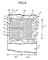
- Fig. 9 illustrates a heat transfer device 70 constructed in accordance with the principles of the invention.
- Device 70 includes a pan 73, a module matrix 72, and a seal layer 71.
- Pan 73 includes bottom 78 and includes outer parallel elongate planar lips or edges 88 and 89 and includes inner parallel inset elongate planar lips or edges 79.
- the construction of lips or edges 88, 89, 79 is similar to the construction of lips or edges 88A, 89A, 79A and 79B In pan 173A in Fig. 10C .
- the construction of pan 73 is similar to that of pan 173A.
- Module matrix 72 includes a plurality of modules 74, 75, 76, 77.
- modules 74, 75, 76, 77 there are sixteen equal sized modules 75 in an upper left hand quadrant I, sixteen equal sized modules 76 in an upper right hand quadrant II, sixteen modules 74 in a lower left hand quadrant III, and sixteen modules 77 in a lower right hand quadrant IV.
- the shape and dimension of each module can, if desired, vary. However, in Fig. 9 each module 74, 75, 76, 77 has an equivalent shape and dimension. Adjacent modules 75 in the upper left hand quadrant are spaced equal distances apart, as are adjacent modules 75 to 77 in the remaining three quadrant illustrated in Fig. 9 .
- module matrix 72 can, and likely would, include additional modules, preferably, but not necessarily, in sub-matrix groupings of four by four (or sixteen total) modules.
- module matrix 172 is that each quadrant I, II, III, IV of sixteen modules is spaced apart from any adjacent modules such that the distance indicated by arrows D5 and D7 is greater than the distance D6 between modules in a quadrant. This facilitates folding or cutting device 70 along axis X and/or Y.
- each module 74 to 77 has an arcuate bottom like modules 77A in Figs. 11B and 11C .
- Providing modules 74 to 77 with arcuate bottoms faciliates pliably bending or deforming device 70 in the manner indicated by arrows 201 and 202 in Fig. 10D for heat transfer device 170.
- the arcuate bottoms of each module 74 to 77 also facilitate the flow of fluid around the bottoms.
- seal layer 71 The peripheral edges of seal layer 71 are fixedly sealingly connected to lips 88, 89 to seal liquid (not visible in Fig, 9 ) that fills pan 73 and surrounds modules 74, 75, 76, 77 and that fills each module 74, 75, 76, 77.
- Layer 71 is sealingly affixed to edges 88 and 89 in the same manner that layer 71 A is affixed to edges 89A and 88A in Fig, 10D .
- distance D5 can vary as desired, D5 is presently preferably in the range of 16 mm to 24 mm.
- the distance D6, D2, D8 between a pair of adjacent modules 74 in a quadrant can vary but is presently preferably eight millimeters to twelve millimeters.
- the diameter or width W1 ( Fig. 11 C) of a module can vary but is presently preferably in the range of 20 mm to 40 mm.
- the depth D1 ( Fig. 11 C) of a module is preferably equal to or about equal to the width of the module.
- the bottom 77C ( Fig. 10D ) of a module contacts the bottom 78, 78A of a pan 73,173A.
- FIG. 10A to 10D A procedure for fabricating a heat transfer device similar to that depicted in Fig. 9 is illustrated Figs. 10A to 10D and 11A to 11C .
- a deformable pliable sheet 73A of a polymer or some other material is provided along with a mold 91.
- Mold 91 includes apertures 92.
- Apparatus (not shown) draws air out from the inside of mold 91 through apertures 92 in the direction indicated by arrow L to draw sheet 73A into the mold and to contour sheet 73A to the inner surface 91A of the mold.
- a follower 90 is also provided to assist sheet 73A in contouring to surface 91A. After suction is applied to draw air in the direction of arrow L and follower 90 is simultaneously moved downwardly in the direction of arrow T, sheet 73A contours to inner surface 91A in the manner illustrated in 10B and a pan 173A is formed.
- pan 173A includes bottom 78A, includes elongate, parallel spaced apart inset edges 79A and 79B, and includes elongate, parallel, spaced apart outer edges 88A and 89A.
- the module matrix 172A produced using the steps illustrated in Figs. 11 A to 11C is inserted in pan 173A in Fig, 10D .
- a deformable pliable sheet 72A of a polymer or some other material is provided along with a mold 96.
- Mold 96 includes openings 97.
- Each opening 97 includes an upright cylindrical wall and a semi-spherical bottom.
- Apparatus (not shown) draws air out from the inside of mold 96 through apertures 97 in the direction indicated by arrow U to draw sheet 72A into the mold and to contour sheet 72A to the inner surfaces 96A of the mold.
- a follower 95 is also provided to assist sheet 72A in contouring to cupped surfaces 96A. After suction is applied to draw air in the direction of arrow U and follower 95 is simultaneously moved downwardly in the direction of arrow V, sheet 72A is contoured to inner surfaces 96A in the manner illustrated in 11 B and a module matrix 172A is formed.
- module matrix 172A includes modules 77A.
- Fig. 11C follower 95 has been removed and nozzles 99 are utilized to inject fluid into modules 77A to form a reservoir 98 in each module 77A.
- the fluid charged module matrix 172A is inserted in the pan 173A of Fig. 10 to produce the module matrix 172A-pan 173A combination illustrated in fig. 10D .
- a layer 71A is applied to seal the fluid reservoirs 98, 94 to complete the production of a heat transfer device in accordance with the invention.
- Layer 71A is continuously sealed to outer edges 88A and 89A.
- module matrix 172A can be inserted in the pan 173A of Fig. 10C before each module 77A is charged with fluid to form reservoirs 98.
- a auxiliary layer similar to layer 71A can be applied to module matrix 172A before matrix 172 A is inserted in pan 173A. This auxiliary layer would seal fluid reservoirs 98 in the matrix 172A. After this sealed matrix 172A is inserted in pan 173A, then layer 71A is applied to seal matrix 172A and reservoir 94 in pan 173A.
- the fluid in reservoirs 98 normally preferably has a different freezing tempering than the fluid in reservoir 94.
- Fig. 9 the fluid in pan 73 and the fluid in each module 74 to 77 has been omitted for the sake of clarity.
- the structure of the heat transfer device 70 of Fig. 9 is generally equivalent to the structure of the heat transfer device illustrated in Fig. 10D except, of course, that the heat transfer device in Fig. 10D includes fewer modules than the heat transfer device 70.
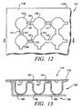
- Figs. 12 and 13 illustrate another heat transfer device 170 constructed in accordance with the invention
- Device 170 is generally equivalent in structure to heat transfer device 70 and to the heat transfer device of Fig. 10D except that modules 75B in the module matrix 72B are Interconnected by semicylindrical channels 100, 102, 104.
- Device 170 includes sealing layer 71 B and pan 73B with bottom 78B. The bottom of each module 75B contacts bottom 78B as illustrated in Fig. 13 .
- Each module 75B is charged with a liquid (not shown), and pan 73B is charged with a liquid (not shown).
- the liquid in modules 75B has a different freezing temperature than the liquid in pan 73B.
Landscapes
- Engineering & Computer Science (AREA)
- Mechanical Engineering (AREA)
- Physics & Mathematics (AREA)
- Thermal Sciences (AREA)
- General Engineering & Computer Science (AREA)
- Health & Medical Sciences (AREA)
- Chemical & Material Sciences (AREA)
- Vascular Medicine (AREA)
- Public Health (AREA)
- Heart & Thoracic Surgery (AREA)
- Combustion & Propulsion (AREA)
- Life Sciences & Earth Sciences (AREA)
- Animal Behavior & Ethology (AREA)
- General Health & Medical Sciences (AREA)
- Biomedical Technology (AREA)
- Veterinary Medicine (AREA)
- Dispersion Chemistry (AREA)
- Thermotherapy And Cooling Therapy Devices (AREA)
- Packages (AREA)
- Physical Or Chemical Processes And Apparatus (AREA)
- Heat-Exchange Devices With Radiators And Conduit Assemblies (AREA)
- Heat Treatment Of Articles (AREA)
Claims (9)
- Biegsame Zweiphasen-Einzelwand-Wärmeübertragungsvorrichtung (32; 50; 80; 70; 170), die verwendet wird, um mit dem Hals oder einem anderen Körperteil einer Person in Kontakt zu treten und davon Wärme abzuziehen, wobei die Wärmeübertragungsvorrichtung Folgendes umfasst:(a) eine Außenwand (73; 73B; 173A), die einen Innenraum (37; 55) abgrenzt und einschließt;(b) mehrere beabstandete hohle fluiddichte Behälter (74, 75, 76, 77, 75B, 77A), die mit einem Teil der Wand verbunden sind und sich von dieser Wand in den Innenraum erstrecken;(c) eine erste Wärmeaustauschzusammensetzung im Innenraum, die mit jedem der fluiddichten Behälter in Kontakt steht und eine Flüssigkeit umfasst, die bei einer gewählten Umwandlungstemperatur eine Zustandsänderung von der flüssigen Phase zur festen Phase erfährt; und(d) eine zweite Wärmeaustauschzusammensetzung in jedem der hohlen Behälter (74, 75, 76, 77, 75B, 77A), die eine Flüssigkeit umfasst, welche bei einer gewählten Umwandlungstemperatur eine Zustandsänderung von der flüssigen Phase zur festen Phase erfährt; dadurch gekennzeichnet, dass jeder der Behälter (74, 75, 76, 77, 75B, 77A) zylinderförmig ist und über Abmessungsgleichheit verfügt, und die zylinderförmigen Behälter abgerundete Böden aufweisen, die mit der Außenwand in Kontakt stehen und das Falten von benachbarten Behältern gegeneinander erleichtern.
- Verfahren zur Herstellung einer Zweiphasen-Einzelwand-Zweirichtungs-Wärmeübertragungsvorrichtung (72, 172), die verwendet wird, um mit dem Hals oder einem anderen Körperteil einer Person in Kontakt zu treten und davon Wärme abzuziehen, wobei das Verfahren die folgenden Schritte umfasst:(a) Bereitstellen eines ersten Bogens (73A, 72A) eines biegsamen Materials;(b) Bilden einer ersten Wanne (73, 173A) mit dem Materialbogen, wobei die Wanne (73, 173A) eine umfängliche Lippe aufweist, die sich um die Wanne erstreckt;(c) Füllen der Wanne (73, 173A) mit einer ersten Wärmeaustauschzusammensetzung, die eine Flüssigkeit umfasst, welche bei einer gewählten Umwandlungstemperatur eine Zustandsänderung von der flüssigen Phase zur festen Phase erfährt;(d) Bereitstellen eines zweiten Bogens eines biegsamen Materials;
gekennzeichnet durch die folgenden Schritte:(e) Bilden einer Modulmatrix (72, 172) mit dem zweiten Materialbogen, wobei die Modulmatrix einen Umfangsrand beinhaltet und die Matrix mehrere Module beinhaltet, wovon jedes einen Boden und eine offene Oberseite aufweist, wobei jedes der Module zylinderförmig ist und über Abmessungsgleichheit verfügt, und die zylinderförmigen Module abgerundete Böden aufweisen;(f) derartiges Anordnen der Modulmatrix (72, 172) in der Wanne, dass sich der abgerundete Boden jedes Moduls in die erste Wärmeaustauschzusammensetzung erstreckt und mit der Wanne in Kontakt steht;(g) Zuführen einer zweiten Wärmeaustauschzusammensetzung zu jedem der Module, die eine Flüssigkeit umfasst, welche bei einer gewählten Umwandlungstemperatur eine Zustandsänderung von der flüssigen Phase zur festen Phase erfährt; und(h) Versiegeln der ersten Zusammensetzung in der Wanne (73; 173A) und der zweiten Zusammensetzung in der Modulmatrix. - Biegsame Zweiphasen-Einzelwand-Wärmeübertragungsvorrichtung nach Anspruch 1, dadurch gekennzeichnet, dass die Vorrichtung ferner Folgendes umfasst:mehrere Kanäle (700, 102, 104), die Paare der hohlen Behälter verbinden, um den Fluss von Flüssigkeit zwischen ihnen zu fördern, um eine gleichmäßigere Verteilung der Wärme zu erleichtern.
- Biegsame Zweiphasen-Einzelwand-Wärmeübertragungsvorrichtung nach Anspruch 1, dadurch gekennzeichnet, dass(a) die gewählte Umwandlungstemperatur der ersten Wärmeaustauschzusammensetzung eine erste Gefriertemperatur umfasst; und(b) die gewählte Umwandlungstemperatur der zweiten Wärmeaustauschzusammensetzung eine zweite Gefriertemperatur umfasst, die höher als die erste Gefriertemperatur ist, so dass die zweite Wärmeaustauschzusammensetzung vor der ersten Wärmeaustauschzusammensetzung gefriert, wenn die Einzelwand-Wärmeübertragungsvorrichtung gekühlt wird.
- Biegsame Zweiphasen-Einzelwand-Wärmeübertragungsvorrichtung nach Anspruch 1 oder Anspruch 4, dadurch gekennzeichnet, dass die zweite Wärmeaustauschzusammensetzung gefroren ist, wenn die Einzelwand-Wärmeübertragungsvorrichtung gekühlt ist.
- Biegsame Zweiphasen-Einzelwand-Wärmeübertragungsvorrichtung nach Anspruch 5, dadurch gekennzeichnet, dass die erste Wärmeaustauschzusammensetzung nicht gefroren ist, wenn die Einzelwand-Wärmeübertragungsvorrichtung gekühlt ist.
- Vorrichtung nach Anspruch 1, dadurch gekennzeichnet, dass die Wärmeübertragungsvorrichtung Folgendes umfasst:eine Wanne (73), die einen Boden (78) beinhaltet;eine Versiegelungsschicht (71), wobei die Wanne (73) und die Versiegelungsschicht (71) den Innenraum abgrenzen, undeine Modulmatrix (72), die mehrere beabstandete hohle Behälter (74, 75, 76, 77) beinhaltet, die jeweils mit dem Boden (78) der Wanne (73) verbunden sind.
- Vorrichtung nach Anspruch 1, wobei(a) die erste Wärmeaustauschzusammensetzung eine Flüssigkeit umfasst, die bei einer gewählten Übergangstemperatur von weniger als -9,44 °C (fünfzehn Grad F) eine Zustandsänderung von der flüssigen Phase zur festen Phase erfährt, wobei die gewählte Übergangstemperatur niedriger als die kältesten Temperaturen ist, die in herkömmlichen Haushalts-Gefrierschränken vorkommen; und(b) die zweite Wärmeaustauschzusammensetzung eine gefrorene zweite Flüssigkeit umfasst, die bei einer Temperatur im Bereich von -9,44 °C bis 0 °C (fünfzehn Grad bis zweiunddreißig Grad F) eine Zustandsänderung von einer flüssigen Phase zu einer gefrorenen festen Phase erfährt, wobei das zweite Fluid einen Gefrierpunkt aufweist, der höher als der Gefrierpunkt des ersten Fluids ist.
- Vorrichtung nach Anspruch 7, wobei der Boden eines jeden der Module mit dem Boden der Wanne in Kontakt steht.
Applications Claiming Priority (4)
| Application Number | Priority Date | Filing Date | Title |
|---|---|---|---|
| US274161 | 1988-11-21 | ||
| US10/274,161 US6904956B2 (en) | 2002-10-18 | 2002-10-18 | Method and thermally active convection apparatus and method for abstracting heat with circulation intermediate three dimensional-parity heat transfer elements in bi-phase heat exchanging composition |
| US463055 | 2003-06-17 | ||
| US10/463,055 US7055575B2 (en) | 2002-10-18 | 2003-06-17 | Thermally active convection apparatus |
Publications (2)
| Publication Number | Publication Date |
|---|---|
| EP1411313A1 EP1411313A1 (de) | 2004-04-21 |
| EP1411313B1 true EP1411313B1 (de) | 2008-05-21 |
Family
ID=32044993
Family Applications (1)
| Application Number | Title | Priority Date | Filing Date |
|---|---|---|---|
| EP03394097A Expired - Lifetime EP1411313B1 (de) | 2002-10-18 | 2003-10-14 | Kühlverfahren und -vorrichtung mit Phasenumwandlungsmaterial enthaltenden Wärmeaustauschelementen |
Country Status (8)
| Country | Link |
|---|---|
| US (2) | US7055575B2 (de) |
| EP (1) | EP1411313B1 (de) |
| AT (1) | ATE396373T1 (de) |
| AU (1) | AU2003255053B2 (de) |
| BR (1) | BR0304608B1 (de) |
| DE (1) | DE60321107D1 (de) |
| MX (1) | MXPA03009397A (de) |
| TW (1) | TWI307402B (de) |
Families Citing this family (28)
| Publication number | Priority date | Publication date | Assignee | Title |
|---|---|---|---|---|
| SE527546C2 (sv) * | 2004-09-15 | 2006-04-04 | Hans Bruce | Sätt och anordning för säkerställande av temperaturhållning i det inre av en transportcontainer eller liknande |
| EP1688108A3 (de) * | 2005-02-07 | 2006-12-13 | Konrad Gadient | Kühl- oder Wärmepackung für medizinische Zwecke |
| NL1029083C2 (nl) * | 2005-05-20 | 2006-11-21 | Breedveldt Beheer B V M | Inrichting voor het koelen van voorwerpen, in het bijzonder een koelmantel voor drankcontainers. |
| US7878994B2 (en) * | 2007-01-29 | 2011-02-01 | Joseph Michael Swope | Cast for immobilizing and heating or cooling a body part |
| DE202007013140U1 (de) * | 2007-09-18 | 2009-02-19 | Rehau Ag + Co | Latentwärmespeichermedium |
| US8776868B2 (en) | 2009-08-28 | 2014-07-15 | International Business Machines Corporation | Thermal ground plane for cooling a computer |
| US20110108020A1 (en) * | 2009-11-11 | 2011-05-12 | Mcenerney Bryan William | Ballast member for reducing active volume of a vessel |
| EP2613748B1 (de) | 2010-09-10 | 2018-09-05 | Medivance Incorporated | Medizinisches kühlungspolster |
| US9622907B2 (en) | 2010-09-10 | 2017-04-18 | Medivance Incorporated | Cooling medical pad |
| CN104364592B (zh) | 2012-01-27 | 2018-02-06 | 确保冷藏有限公司 | 制冷设备 |
| CN103245105B (zh) * | 2012-02-10 | 2016-06-15 | 北京清华阳光能源开发有限责任公司 | 带固液工质包的玻璃热管及其制造方法 |
| USD685916S1 (en) | 2012-11-26 | 2013-07-09 | Medivance Incorporated | Medical cooling pad |
| GB201301494D0 (en) | 2013-01-28 | 2013-03-13 | True Energy Ltd | Refrigeration apparatus |
| GB2518727B (en) | 2013-07-23 | 2017-05-24 | The Sure Chill Company Ltd | Refrigeration apparatus and method |
| EP2842528A1 (de) | 2013-09-03 | 2015-03-04 | Ampac Enterprises Inc. | Vorrichtung und Verfahren zum Kühlen einer Kopfverletzung |
| US10356944B2 (en) * | 2013-10-29 | 2019-07-16 | Sekisui Polymatech Co., Ltd. | Liquid-encapsulation heat dissipation member |
| US20150211805A1 (en) * | 2014-01-29 | 2015-07-30 | Kunshan Jue-Chung Electronics Co., Ltd. | Thermostat module |
| JP6787903B2 (ja) | 2015-01-27 | 2020-11-18 | メディヴァンス インコーポレイテッドMedivance,Inc. | 熱療法用の改良された医療用パッド及びシステム |
| CN108351146B (zh) * | 2015-09-11 | 2021-04-20 | 确保冷藏有限公司 | 便携式制冷设备 |
| US10377407B2 (en) * | 2017-02-08 | 2019-08-13 | Toyota Motor Engineering & Manufacturing North America, Inc. | Cooling systems for vehicle interior surfaces |
| CN106839555B (zh) * | 2017-02-14 | 2023-03-03 | 安派智厨(浙江)有限公司 | 雪花机滚筒 |
| GB2567690B (en) * | 2017-10-23 | 2019-10-23 | Robert Ingam Philip | Cooling elements and cooling assemblies comprising same |
| CA3096238A1 (en) * | 2018-04-05 | 2019-10-10 | Zehnder Group International Ag | Exchanger element for a vehicle and vehicle equipped with such an exchanger element |
| US11181323B2 (en) * | 2019-02-21 | 2021-11-23 | Qualcomm Incorporated | Heat-dissipating device with interfacial enhancements |
| US12496215B2 (en) | 2021-01-25 | 2025-12-16 | C. R. Bard, Inc. | Transparent pad |
| US12433785B2 (en) | 2021-02-23 | 2025-10-07 | C. R. Bard, Inc. | Gel pad assembly using free rotatable fluid joints |
| US12241570B2 (en) | 2021-07-07 | 2025-03-04 | C. R. Bard, Inc. | Negative pressure connector seal |
| GB202400207D0 (en) * | 2024-01-07 | 2024-02-21 | Paxman Coolers Ltd | Scalp cooling cap |
Family Cites Families (30)
| Publication number | Priority date | Publication date | Assignee | Title |
|---|---|---|---|---|
| US2602302A (en) * | 1947-06-13 | 1952-07-08 | Noel J Poux | Combination ice and hot pack |
| US2595328A (en) * | 1949-04-29 | 1952-05-06 | Goodrich Co B F | Heat-transfer container |
| US3506013A (en) * | 1966-10-14 | 1970-04-14 | Betty J Zdenek | Method of making iced dressing |
| AT310225B (de) * | 1969-02-03 | 1973-09-25 | Beteiligungs Ag Haustechnik | Heiz- und Wärmespeichervorrichtung zur Verhinderung der Vereisung von Außenflächen |
| JPS5341358A (en) | 1976-09-28 | 1978-04-14 | Ibiden Co Ltd | Apparatus for preparation of inorganic fibreboards |
| US4355627A (en) * | 1978-06-06 | 1982-10-26 | Scarlata Robert W | Thermal storage system |
| US4335781A (en) * | 1978-10-02 | 1982-06-22 | Motorola Inc. | High power cooler and method thereof |
| JPS5610697A (en) * | 1979-07-07 | 1981-02-03 | Agency Of Ind Science & Technol | Composite heat accumulator |
| DE2942126C2 (de) * | 1979-10-18 | 1982-10-14 | L. & C. Steinmüller GmbH, 5270 Gummersbach | Wärmeleitelemente für regenerativen Wärmeaustausch |
| JPS57490A (en) | 1980-05-30 | 1982-01-05 | Kanai Hiroyuki | Double structure heat pipe |
| JPS57188990A (en) | 1981-05-18 | 1982-11-20 | Toshiba Corp | Heat accumulating body |
| EP0074612B1 (de) * | 1981-09-11 | 1986-01-02 | Hitachi, Ltd. | Wärmespeicher |
| US4753241A (en) * | 1984-06-01 | 1988-06-28 | Fastencold, Inc. | Method of forming and using a therapeutic device |
| EP0270553B1 (de) * | 1986-05-16 | 1991-08-21 | TERM-ac S.A. | Therapeutische vorrichtung mit einer masse aus einem thermisch aktiven material |
| JPS6438593A (en) | 1987-07-31 | 1989-02-08 | Toshiba Corp | Thermal accumulation device |
| US5163504A (en) * | 1988-07-08 | 1992-11-17 | Resnick Joseph A | Container heating or cooling device and building material |
| JPH02287096A (ja) | 1989-04-27 | 1990-11-27 | Mitsubishi Kakoki Kaisha Ltd | 蓄熱シート及びその製造方法 |
| US5036904A (en) * | 1989-12-04 | 1991-08-06 | Chiyoda Corporation | Latent heat storage tank |
| US4976308A (en) * | 1990-02-21 | 1990-12-11 | Wright State University | Thermal energy storage heat exchanger |
| US5000252A (en) * | 1990-02-22 | 1991-03-19 | Wright State University | Thermal energy storage system |
| JPH0696343A (ja) * | 1992-09-14 | 1994-04-08 | Sanden Corp | 蓄熱ユニット |
| US5423996A (en) * | 1994-04-15 | 1995-06-13 | Phase Change Laboratories, Inc. | Compositions for thermal energy storage or thermal energy generation |
| DE4415946C2 (de) * | 1994-05-05 | 1999-07-22 | Thomas Dr Lange | Flexible Kühlpackung |
| US5840080A (en) * | 1996-08-15 | 1998-11-24 | Der Ovanesian; Mary | Hot or cold applicator with inner element |
| US6083256A (en) * | 1996-08-15 | 2000-07-04 | Der Ovanesian; Mary | NNT or cold pad with inner element |
| SG64996A1 (en) * | 1997-07-08 | 1999-05-25 | Dso National Laborataries | A heat sink |
| SE9900711L (sv) * | 1998-08-07 | 2000-02-08 | Flexi Ice Ab | Termiskt omslag |
| US6497116B2 (en) * | 2001-02-02 | 2002-12-24 | Thomas P. Noel | Apparatus for abstracting heat with a solid--liquid matrix utilizing a kinetic--circulation--kinetic heat transfer cycle |
| US6904956B2 (en) * | 2002-10-18 | 2005-06-14 | Thomas P. Noel | Method and thermally active convection apparatus and method for abstracting heat with circulation intermediate three dimensional-parity heat transfer elements in bi-phase heat exchanging composition |
| US6439298B1 (en) * | 2001-04-17 | 2002-08-27 | Jia Hao Li | Cylindrical heat radiator |
-
2003
- 2003-06-17 US US10/463,055 patent/US7055575B2/en not_active Expired - Lifetime
- 2003-10-08 TW TW092127921A patent/TWI307402B/zh not_active IP Right Cessation
- 2003-10-14 EP EP03394097A patent/EP1411313B1/de not_active Expired - Lifetime
- 2003-10-14 DE DE60321107T patent/DE60321107D1/de not_active Expired - Lifetime
- 2003-10-14 AT AT03394097T patent/ATE396373T1/de not_active IP Right Cessation
- 2003-10-14 MX MXPA03009397A patent/MXPA03009397A/es unknown
- 2003-10-16 BR BRPI0304608-7B1A patent/BR0304608B1/pt not_active IP Right Cessation
- 2003-10-17 AU AU2003255053A patent/AU2003255053B2/en not_active Ceased
-
2007
- 2007-05-31 US US11/809,205 patent/US20080047684A1/en not_active Abandoned
Also Published As
| Publication number | Publication date |
|---|---|
| MXPA03009397A (es) | 2005-04-11 |
| US20060032614A9 (en) | 2006-02-16 |
| AU2003255053A1 (en) | 2004-05-06 |
| ATE396373T1 (de) | 2008-06-15 |
| EP1411313A1 (de) | 2004-04-21 |
| TWI307402B (en) | 2009-03-11 |
| BR0304608B1 (pt) | 2014-01-07 |
| TW200419129A (en) | 2004-10-01 |
| US20080047684A1 (en) | 2008-02-28 |
| BR0304608A (pt) | 2005-03-01 |
| DE60321107D1 (de) | 2008-07-03 |
| US20040256087A1 (en) | 2004-12-23 |
| AU2003255053B2 (en) | 2008-07-31 |
| US7055575B2 (en) | 2006-06-06 |
Similar Documents
| Publication | Publication Date | Title |
|---|---|---|
| EP1411313B1 (de) | Kühlverfahren und -vorrichtung mit Phasenumwandlungsmaterial enthaltenden Wärmeaustauschelementen | |
| CA2444837C (en) | Method and thermally active convection apparatus and method for abstracting heat with circulation intermediate three dimensional-parity heat transfer elements in bi-phase heat exchanging composition | |
| US7240720B2 (en) | Method and thermally active multi-phase heat transfer apparatus and method for abstracting heat using liquid bi-phase heat exchanging composition | |
| US4827735A (en) | Off peak storage device | |
| US2595328A (en) | Heat-transfer container | |
| US3545230A (en) | Flexible cooling device and use thereof | |
| US5843145A (en) | Reusable hot/cold temperature pack | |
| AU730134B2 (en) | Latent heat body | |
| US20040024438A1 (en) | Therapeutic pack | |
| CN104441654B (zh) | 一种三维生物打印装置及方法 | |
| KR940007193B1 (ko) | 용융-결정화의 높은 잠정적 열을 갖는 에너지 저장매체 리시피언트(recipient) | |
| KR20060109450A (ko) | 열 쿠션 및 이 열 쿠션을 포함하는 장치 | |
| US6497116B2 (en) | Apparatus for abstracting heat with a solid--liquid matrix utilizing a kinetic--circulation--kinetic heat transfer cycle | |
| CN2398998Y (zh) | 柔性冰袋 | |
| MXPA98010113A (es) | Conjunto de torre de enfriamiento con material derelleno esferico. | |
| JPS62501478A (ja) | エネルギ−供給型あるいは奪取型の医療用湿布材 | |
| JP3112723U (ja) | 携帯用小型保冷容器 | |
| US10687632B1 (en) | PCM containing liquid saturated foam device | |
| CN220512553U (zh) | 冰垫及用于冰垫的冰晶粉袋 | |
| JPH10234767A (ja) | 蓄熱パックおよび蓄熱パック具 | |
| JP3574643B2 (ja) | ワイン等の冷却器 | |
| CN223765136U (zh) | 一种用于透析病人的药品暂存盒 | |
| JPH04332557A (ja) | 血小板輸送システム | |
| JPH02115693A (ja) | 潜熱蓄熱システム | |
| JP3364589B2 (ja) | 熱電モジュールを内蔵するマニホールド、冷蔵庫及び冷却装置 |
Legal Events
| Date | Code | Title | Description |
|---|---|---|---|
| PUAI | Public reference made under article 153(3) epc to a published international application that has entered the european phase |
Free format text: ORIGINAL CODE: 0009012 |
|
| AK | Designated contracting states |
Kind code of ref document: A1 Designated state(s): AT BE BG CH CY CZ DE DK EE ES FI FR GB GR HU IE IT LI LU MC NL PT RO SE SI SK TR |
|
| AX | Request for extension of the european patent |
Extension state: AL LT LV MK |
|
| 17P | Request for examination filed |
Effective date: 20041012 |
|
| AKX | Designation fees paid |
Designated state(s): AT BE BG CH CY CZ DE DK EE ES FI FR GB GR HU IE IT LI LU MC NL PT RO SE SI SK TR |
|
| 17Q | First examination report despatched |
Effective date: 20050315 |
|
| 17Q | First examination report despatched |
Effective date: 20050315 |
|
| GRAP | Despatch of communication of intention to grant a patent |
Free format text: ORIGINAL CODE: EPIDOSNIGR1 |
|
| GRAS | Grant fee paid |
Free format text: ORIGINAL CODE: EPIDOSNIGR3 |
|
| GRAA | (expected) grant |
Free format text: ORIGINAL CODE: 0009210 |
|
| AK | Designated contracting states |
Kind code of ref document: B1 Designated state(s): AT BE BG CH CY CZ DE DK EE ES FI FR GB GR HU IE IT LI LU MC NL PT RO SE SI SK TR |
|
| REG | Reference to a national code |
Ref country code: GB Ref legal event code: FG4D |
|
| REG | Reference to a national code |
Ref country code: CH Ref legal event code: EP |
|
| REF | Corresponds to: |
Ref document number: 60321107 Country of ref document: DE Date of ref document: 20080703 Kind code of ref document: P |
|
| REG | Reference to a national code |
Ref country code: IE Ref legal event code: FG4D |
|
| PG25 | Lapsed in a contracting state [announced via postgrant information from national office to epo] |
Ref country code: SI Free format text: LAPSE BECAUSE OF FAILURE TO SUBMIT A TRANSLATION OF THE DESCRIPTION OR TO PAY THE FEE WITHIN THE PRESCRIBED TIME-LIMIT Effective date: 20080521 |
|
| PG25 | Lapsed in a contracting state [announced via postgrant information from national office to epo] |
Ref country code: FI Free format text: LAPSE BECAUSE OF FAILURE TO SUBMIT A TRANSLATION OF THE DESCRIPTION OR TO PAY THE FEE WITHIN THE PRESCRIBED TIME-LIMIT Effective date: 20080521 Ref country code: ES Free format text: LAPSE BECAUSE OF FAILURE TO SUBMIT A TRANSLATION OF THE DESCRIPTION OR TO PAY THE FEE WITHIN THE PRESCRIBED TIME-LIMIT Effective date: 20080901 |
|
| NLV1 | Nl: lapsed or annulled due to failure to fulfill the requirements of art. 29p and 29m of the patents act | ||
| PG25 | Lapsed in a contracting state [announced via postgrant information from national office to epo] |
Ref country code: AT Free format text: LAPSE BECAUSE OF FAILURE TO SUBMIT A TRANSLATION OF THE DESCRIPTION OR TO PAY THE FEE WITHIN THE PRESCRIBED TIME-LIMIT Effective date: 20080521 Ref country code: NL Free format text: LAPSE BECAUSE OF FAILURE TO SUBMIT A TRANSLATION OF THE DESCRIPTION OR TO PAY THE FEE WITHIN THE PRESCRIBED TIME-LIMIT Effective date: 20080521 |
|
| PG25 | Lapsed in a contracting state [announced via postgrant information from national office to epo] |
Ref country code: PT Free format text: LAPSE BECAUSE OF FAILURE TO SUBMIT A TRANSLATION OF THE DESCRIPTION OR TO PAY THE FEE WITHIN THE PRESCRIBED TIME-LIMIT Effective date: 20081021 Ref country code: CZ Free format text: LAPSE BECAUSE OF FAILURE TO SUBMIT A TRANSLATION OF THE DESCRIPTION OR TO PAY THE FEE WITHIN THE PRESCRIBED TIME-LIMIT Effective date: 20080521 Ref country code: SE Free format text: LAPSE BECAUSE OF FAILURE TO SUBMIT A TRANSLATION OF THE DESCRIPTION OR TO PAY THE FEE WITHIN THE PRESCRIBED TIME-LIMIT Effective date: 20080821 Ref country code: DK Free format text: LAPSE BECAUSE OF FAILURE TO SUBMIT A TRANSLATION OF THE DESCRIPTION OR TO PAY THE FEE WITHIN THE PRESCRIBED TIME-LIMIT Effective date: 20080521 |
|
| PG25 | Lapsed in a contracting state [announced via postgrant information from national office to epo] |
Ref country code: SK Free format text: LAPSE BECAUSE OF FAILURE TO SUBMIT A TRANSLATION OF THE DESCRIPTION OR TO PAY THE FEE WITHIN THE PRESCRIBED TIME-LIMIT Effective date: 20080521 Ref country code: RO Free format text: LAPSE BECAUSE OF FAILURE TO SUBMIT A TRANSLATION OF THE DESCRIPTION OR TO PAY THE FEE WITHIN THE PRESCRIBED TIME-LIMIT Effective date: 20080521 Ref country code: BE Free format text: LAPSE BECAUSE OF FAILURE TO SUBMIT A TRANSLATION OF THE DESCRIPTION OR TO PAY THE FEE WITHIN THE PRESCRIBED TIME-LIMIT Effective date: 20080521 |
|
| PLBE | No opposition filed within time limit |
Free format text: ORIGINAL CODE: 0009261 |
|
| STAA | Information on the status of an ep patent application or granted ep patent |
Free format text: STATUS: NO OPPOSITION FILED WITHIN TIME LIMIT |
|
| 26N | No opposition filed |
Effective date: 20090224 |
|
| PG25 | Lapsed in a contracting state [announced via postgrant information from national office to epo] |
Ref country code: EE Free format text: LAPSE BECAUSE OF FAILURE TO SUBMIT A TRANSLATION OF THE DESCRIPTION OR TO PAY THE FEE WITHIN THE PRESCRIBED TIME-LIMIT Effective date: 20080521 Ref country code: BG Free format text: LAPSE BECAUSE OF FAILURE TO SUBMIT A TRANSLATION OF THE DESCRIPTION OR TO PAY THE FEE WITHIN THE PRESCRIBED TIME-LIMIT Effective date: 20080821 |
|
| PG25 | Lapsed in a contracting state [announced via postgrant information from national office to epo] |
Ref country code: MC Free format text: LAPSE BECAUSE OF NON-PAYMENT OF DUE FEES Effective date: 20081031 |
|
| REG | Reference to a national code |
Ref country code: CH Ref legal event code: PL |
|
| REG | Reference to a national code |
Ref country code: IE Ref legal event code: MM4A |
|
| PG25 | Lapsed in a contracting state [announced via postgrant information from national office to epo] |
Ref country code: CH Free format text: LAPSE BECAUSE OF NON-PAYMENT OF DUE FEES Effective date: 20081031 Ref country code: IE Free format text: LAPSE BECAUSE OF NON-PAYMENT OF DUE FEES Effective date: 20081014 Ref country code: LI Free format text: LAPSE BECAUSE OF NON-PAYMENT OF DUE FEES Effective date: 20081031 |
|
| PG25 | Lapsed in a contracting state [announced via postgrant information from national office to epo] |
Ref country code: CY Free format text: LAPSE BECAUSE OF FAILURE TO SUBMIT A TRANSLATION OF THE DESCRIPTION OR TO PAY THE FEE WITHIN THE PRESCRIBED TIME-LIMIT Effective date: 20080521 Ref country code: LU Free format text: LAPSE BECAUSE OF NON-PAYMENT OF DUE FEES Effective date: 20081014 Ref country code: HU Free format text: LAPSE BECAUSE OF FAILURE TO SUBMIT A TRANSLATION OF THE DESCRIPTION OR TO PAY THE FEE WITHIN THE PRESCRIBED TIME-LIMIT Effective date: 20081122 |
|
| PG25 | Lapsed in a contracting state [announced via postgrant information from national office to epo] |
Ref country code: TR Free format text: LAPSE BECAUSE OF FAILURE TO SUBMIT A TRANSLATION OF THE DESCRIPTION OR TO PAY THE FEE WITHIN THE PRESCRIBED TIME-LIMIT Effective date: 20080521 |
|
| PG25 | Lapsed in a contracting state [announced via postgrant information from national office to epo] |
Ref country code: GR Free format text: LAPSE BECAUSE OF FAILURE TO SUBMIT A TRANSLATION OF THE DESCRIPTION OR TO PAY THE FEE WITHIN THE PRESCRIBED TIME-LIMIT Effective date: 20080822 |
|
| PGFP | Annual fee paid to national office [announced via postgrant information from national office to epo] |
Ref country code: IT Payment date: 20120430 Year of fee payment: 9 |
|
| PG25 | Lapsed in a contracting state [announced via postgrant information from national office to epo] |
Ref country code: IT Free format text: LAPSE BECAUSE OF NON-PAYMENT OF DUE FEES Effective date: 20121014 |
|
| REG | Reference to a national code |
Ref country code: FR Ref legal event code: PLFP Year of fee payment: 12 |
|
| REG | Reference to a national code |
Ref country code: FR Ref legal event code: PLFP Year of fee payment: 13 |
|
| PGFP | Annual fee paid to national office [announced via postgrant information from national office to epo] |
Ref country code: DE Payment date: 20161031 Year of fee payment: 14 |
|
| REG | Reference to a national code |
Ref country code: FR Ref legal event code: PLFP Year of fee payment: 14 |
|
| PGFP | Annual fee paid to national office [announced via postgrant information from national office to epo] |
Ref country code: GB Payment date: 20170428 Year of fee payment: 14 Ref country code: FR Payment date: 20170428 Year of fee payment: 14 |
|
| REG | Reference to a national code |
Ref country code: DE Ref legal event code: R119 Ref document number: 60321107 Country of ref document: DE |
|
| GBPC | Gb: european patent ceased through non-payment of renewal fee |
Effective date: 20171014 |
|
| REG | Reference to a national code |
Ref country code: FR Ref legal event code: ST Effective date: 20180629 |
|
| PG25 | Lapsed in a contracting state [announced via postgrant information from national office to epo] |
Ref country code: DE Free format text: LAPSE BECAUSE OF NON-PAYMENT OF DUE FEES Effective date: 20180501 Ref country code: GB Free format text: LAPSE BECAUSE OF NON-PAYMENT OF DUE FEES Effective date: 20171014 |
|
| PG25 | Lapsed in a contracting state [announced via postgrant information from national office to epo] |
Ref country code: FR Free format text: LAPSE BECAUSE OF NON-PAYMENT OF DUE FEES Effective date: 20171031 |