EP1411249A1 - Kreiselpumpeneinheit - Google Patents
Kreiselpumpeneinheit Download PDFInfo
- Publication number
- EP1411249A1 EP1411249A1 EP03022413A EP03022413A EP1411249A1 EP 1411249 A1 EP1411249 A1 EP 1411249A1 EP 03022413 A EP03022413 A EP 03022413A EP 03022413 A EP03022413 A EP 03022413A EP 1411249 A1 EP1411249 A1 EP 1411249A1
- Authority
- EP
- European Patent Office
- Prior art keywords
- housing
- lantern
- pump
- ring
- pump unit
- Prior art date
- Legal status (The legal status is an assumption and is not a legal conclusion. Google has not performed a legal analysis and makes no representation as to the accuracy of the status listed.)
- Granted
Links
- 238000007789 sealing Methods 0.000 claims description 9
- 230000008878 coupling Effects 0.000 claims description 6
- 238000010168 coupling process Methods 0.000 claims description 6
- 238000005859 coupling reaction Methods 0.000 claims description 6
- 230000007704 transition Effects 0.000 claims 1
- 239000002184 metal Substances 0.000 description 6
- 238000010276 construction Methods 0.000 description 5
- 230000002787 reinforcement Effects 0.000 description 4
- 239000000463 material Substances 0.000 description 3
- 239000007858 starting material Substances 0.000 description 3
- 230000035508 accumulation Effects 0.000 description 2
- 238000009825 accumulation Methods 0.000 description 2
- 230000006978 adaptation Effects 0.000 description 2
- 230000001419 dependent effect Effects 0.000 description 2
- 238000004519 manufacturing process Methods 0.000 description 2
- 230000008901 benefit Effects 0.000 description 1
- 230000008859 change Effects 0.000 description 1
- 230000000694 effects Effects 0.000 description 1
- 238000005516 engineering process Methods 0.000 description 1
- 230000002349 favourable effect Effects 0.000 description 1
- 230000002093 peripheral effect Effects 0.000 description 1
- 239000011148 porous material Substances 0.000 description 1
- 238000003466 welding Methods 0.000 description 1
Images

Classifications
-
- F—MECHANICAL ENGINEERING; LIGHTING; HEATING; WEAPONS; BLASTING
- F04—POSITIVE - DISPLACEMENT MACHINES FOR LIQUIDS; PUMPS FOR LIQUIDS OR ELASTIC FLUIDS
- F04D—NON-POSITIVE-DISPLACEMENT PUMPS
- F04D13/00—Pumping installations or systems
- F04D13/02—Units comprising pumps and their driving means
- F04D13/021—Units comprising pumps and their driving means containing a coupling
-
- F—MECHANICAL ENGINEERING; LIGHTING; HEATING; WEAPONS; BLASTING
- F04—POSITIVE - DISPLACEMENT MACHINES FOR LIQUIDS; PUMPS FOR LIQUIDS OR ELASTIC FLUIDS
- F04D—NON-POSITIVE-DISPLACEMENT PUMPS
- F04D29/00—Details, component parts, or accessories
- F04D29/40—Casings; Connections of working fluid
- F04D29/42—Casings; Connections of working fluid for radial or helico-centrifugal pumps
- F04D29/426—Casings; Connections of working fluid for radial or helico-centrifugal pumps especially adapted for liquid pumps
- F04D29/4266—Casings; Connections of working fluid for radial or helico-centrifugal pumps especially adapted for liquid pumps made of sheet metal
-
- F—MECHANICAL ENGINEERING; LIGHTING; HEATING; WEAPONS; BLASTING
- F04—POSITIVE - DISPLACEMENT MACHINES FOR LIQUIDS; PUMPS FOR LIQUIDS OR ELASTIC FLUIDS
- F04D—NON-POSITIVE-DISPLACEMENT PUMPS
- F04D29/00—Details, component parts, or accessories
- F04D29/60—Mounting; Assembling; Disassembling
- F04D29/62—Mounting; Assembling; Disassembling of radial or helico-centrifugal pumps
- F04D29/628—Mounting; Assembling; Disassembling of radial or helico-centrifugal pumps especially adapted for liquid pumps
Definitions
- the invention relates to a centrifugal pump unit with a front and a rear housing part existing pump housing, on the front Housing part coaxial to the pump axis and an inlet connector at the rear Housing part, opposite the inlet connection, precautions for fastening of a lantern housing, which carries the pump housing freely and over the rear housing part connects to a drive motor, are provided, as well with an impeller, which is located outside of the pump housing, sealed in the interior of which shaft is driven, and with an impeller encompassing the pump housing Ring channel, preferably a spiral housing, which has a pressure port.
- Thin-walled housings for centrifugal pumps primarily those in sheet metal construction, are increasingly competing with those with thick-walled housings, preferably those in cast design, where the price / performance ratio on the one hand and the weight, the absence of pores and the surface quality of the rolled starting material on the other hand are decisive Selection criteria for a centrifugal pump. Housing wall thicknesses made in rolled material are only dependent on the working pressure of the centrifugal pump, while for cast housings, for technological reasons, a minimum wall thickness must not be undercut, which in many cases is oversized with regard to the stresses that occur.
- cast housings are generally considered to be dimensionally stable and thus more reliable; their shape is well known (see for example DE 25 29 458 C2 or company publication 5.046.1, Tuchenhagen, centrifugal pumps, series VPB, VPC, VPD ... L, Otto Tuchenhagen GmbH & Co. KG, D-21510 Büchen).
- centrifugal pump Today, it becomes acceptable wherever low efficiency losses are acceptable and on the other hand the cost of such a centrifugal pump is one play a crucial role in the selection, for cost-effective solutions for Centrifugal pumps in sheet metal construction wanted.
- the desire for one in all areas is predominantly relatively thin-walled centrifugal pump construction, however not tied to the use of sheet metal as the starting material if the required thin walls is possible through alternative manufacturing processes.
- centrifugal pumps of a pump series that are differentiate according to delivery head and / or volume flow, with the lowest possible Generate design and adjustment effort. This succeeds on the one hand by radial enlargement of the impeller and thus a corresponding one Enlargement of the housing comprising the impeller and on the other hand by axially widening the impeller and thus a corresponding axial enlargement of the blade-free annular space surrounding the impeller if necessary in connection with an annular channel, which is designed as a spiral housing can be.
- Centrifugal pumps with different outputs of a pump series require correspondingly adapted drive motors, the latter a connection flange on each end of the motor shaft have, whose flange diameter usually depends on the engine power is dependent.
- connection flange or the so-called bearing plate the drive motor via a so-called lantern housing with the rear housing part to connect the pump housing (Fristam pumps, F. Stamp KG, Hamburg, centrifugal pump FP 700, FP34, FP35, E8612002, before 1993).
- the lantern housing via a recess on the motor side, creating a coaxial Centering between the lantern housing and the connection flange of the motor is.
- the connection between the lantern housing and the connection flange is thereby over several arranged over the circumference of the connecting flange, through this reaching and screwed to the lantern housing Hexagon bolts reached.
- connection between the lantern and pump housing is comparable Way, namely in that the rear housing part of the pump housing a ring-shaped, structurally relatively complex reinforcement with a recess has, on which the lantern housing is coaxially centered and also by means of Screws distributed over the circumference are detachably fastened.
- the rear housing part in the form of a cast part possible, the accumulation of material primarily due to the screw connections on the rear part of the housing in the area of the circular circumferential Reinforcement only for an axially very limited coaxial guidance between the rear housing part and the lantern housing attached to it can.
- the known solution of connecting the lantern housing on the one hand the pump housing which is available in different sizes and capacities and on the other hand with the engine adjusted accordingly in performance not on thin-walled housings, primarily those in sheet metal construction, transfer.
- centrifugal pump unit which, without that it is determined from the outset to be a sheet metal construction, mostly is relatively thin-walled and on the one hand low weight with high rigidity and, on the other hand, a high degree due to the shape variability in pump performance with little adjustment effort different sizes of the drive motors connects.
- the ring channel integrated in the pump housing is in any case outside of the pump-side lantern flange, so that the impeller widened and / or an increase in the impeller diameter and a change the ring channel cross-section has no effect on the attachment between Pump housing and lantern flange on the pump side.
- the the Guiding cylindrical receiving bore in the cylindrical part of the Lantern housing has the relatively small guide diameter d.
- Corresponding is dimensioned corresponding to the cylindrical mounting hole cylindrical receptacle housing that connects to the back surface of the rear housing part continues in the axial direction.
- the relatively small guide diameter d allows a very precise tolerance of the game fit between the cylindrical mounting hole in the lantern housing and the cylindrical Receiving housing on the rear housing part, so that the largest possible Coaxiality between the pump and lantern housing is ensured.
- centrifugal pump unit form the pump-side lantern flange and the rear surface of the rear Housing part together a first mounting surface that is perpendicular to the pump axis is oriented and has a relatively short radial extension. Thereby becomes a statically clear and rigid connection between the pump Lantern housing reached.
- the invention proposes continue to face that the back surface and the pump-side lantern flange over several threaded bolts are screwed together (first screw connections), which are arranged in a pitch circle arrangement on the connection diameter and are integrally connected to the back surface.
- first screw connections screwed together
- the integral connection the threaded bolt with the rear surface is made, for example, by resistance welding, so that the rear surface in the connection area has no reinforcement must experience.
- the front housing part is over a Outside diameter centered on the rear housing part, which is outside the outer Dimension of the ring channel is located.
- the proposed solution provides for this furthermore, that the rear housing part, seen in the radial direction, as far as possible outside the outer radial dimension of the ring channel in a wall part with a radially oriented third ring surface, and that an outer surface of the wall part forming the third ring surface of a first Recess is included, which is formed on a on the front housing part with which third ring surface corresponding first ring surface is arranged.
- the radial Extension of the corresponding and connected ring surfaces is dimensioned such that there are several, distributed over the circumference can easily accommodate second screw connections.
- the coaxial centering of the front housing part on the rear housing part via one on the pump housing conceivable creates the largest possible outer diameter favorable conditions for the greatest possible coaxiality between these Housing parts.
- the seal between the front and rear housing part against the Interior of the ring channel is preferably carried out by a in the rear housing part arranged housing seal, which is arranged so that it fits into a gap between the front and rear housing part towards the interior of the Beaded out ring channel.
- the third ring surface opposite a second axially delimiting the ring channel Ring surface axially offset from the ring channel offset axially on the second ring surface is arranged, and that for sealing between the first and the third ring surface, a housing seal is provided, which in a Transitional area between the second and third ring surfaces and at the Interior of the annular channel adjacent sealing groove is inserted.
- the above-mentioned axial offset results in the inside diameter of the housing seal a housing-side paragraph, on the one hand the contact surface and on the other Creates space for the aforementioned housing seal.
- a radially widening conical part adjoins the cylindrical part of the lantern housing, which has the same shape and dimensions for all pump sizes of a pump series, and ends on the outside in a radially oriented lantern flange on the drive side, with a second recess.
- the different lantern housings consequently always have identical guide diameters d and connection diameters D i on the pump housing, and on the other hand they each have different conicity in the direction of the lantern flange on the drive side, which in each case has a flange diameter D determined by a second recess.
- the conical part of the lantern housing which widens from the relatively small guide diameter d to the relatively large flange diameter D gives the latter an extraordinary strength and stability with a relatively thin-walled design.
- the interior of the conical part is sufficiently dimensioned to accommodate a shaft coupling there.
- the conical tapering of the lantern housing towards the pump housing easy access from the outside to the connection point on the pump side Lantern flange with the pump housing and the other to the connection point between the front and rear housing parts of the pump housing.
- connection between the shaft of the centrifugal pump and the motor shaft is made in an advantageous manner via a trained as a clamp connection, within the Lantern housing arranged shaft coupling.
- This solution has the advantage that the respective drive motor with a standard stub shaft Motor shaft can be formed.
- a motor shaft designed as a special shaft, which is suitable, the pump impeller and the subsequent mechanical seal is therefore, as is often the case with solutions according to the state of the art Technology is the case not to provide.
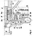
- a centrifugal pump unit 1 consists of a pump housing 2, 3 and a lantern housing 4 ( FIG. 1 ).
- an inlet connection 5 and, circumferentially, tangentially opening, a pressure connection 7 are connected to the front housing part 2.
- the front and rear housing parts 2, 3 are in their radial extent adapted to an impeller 8, each with a narrow annular gap.
- the circumferential outlet cross section closes on the outside a blade-less Annular space 6a on the face of a lateral surface of a cover surface 2b of the front housing part 2 is bordered.
- This cover surface 2b then settles and circumferentially in an outer annular channel wall 2c, this preferably has the shape of a cylinder jacket, i.e. a constant radius of curvature has.
- the rear housing part 3 is in the area of the impeller 8 as radially extending rear surface 3b formed.
- This Rear surface 3b closes an inner annular channel wall oriented in the axial direction 3c, whose local radius of curvature is variable over the circumference, if, as seen in the direction of flow, there is an attachment to the vane-free annular space 6a subsequent ring channel 6 is formed in the form of a spiral housing.
- This Traps form the outer and inner ring channel walls 2c, 3c between them the constantly changing passage cross section of the spiral housing Ring channel 6 out.
- This ring channel 6 has a volume flow ratio axial extension adapted to the respective centrifugal pump.
- the rear housing part 3 merges with the rear surface 3b on the inside into a cylindrical receiving housing 3a, which is essentially cylindrical, has a guide diameter d on the outside and is accommodated in a cylindrical receiving bore 4f in an essentially cylindrical part 4a of the lantern housing 4 ,
- the lantern and pump housings 4 and 2, 3 are centered on the guide diameter d exactly coaxially to one another via the cylindrical receiving bore 4f.
- a lantern flange 4c on the pump side which extends in a plane perpendicular to the pump axis and, starting from the guide diameter d, radially outwards, adjoins the cylindrical part 4a and is detachably fastened to the rear surface 3b via a first fastening surface F 1 .
- first screw connections 11 are provided on a connection diameter D i , in the immediate vicinity of the mounting hole 4f and distributed over the circumference of the connection diameter D i ( FIG. 2 ), threaded bolts 11a are preferably fixed to the rear surface 3b via through holes 4h im Reach through the lantern flange 4c on the pump side and screw the latter to the rear surface 3b using nuts 11b.
- the essentially cylindrical part 4a of the lantern housing 4 continues on the drive side in a conical part 4b which widens outwards to a flange diameter D of a second recess 4e.
- the lantern housing 4 is centered on a connection flange 10 of the drive motor 15 via the latter.
- the conical part 4b seen in the radial direction, merges outside the second recess 4e into a radially oriented drive-side lantern flange 4d which is connected to the connection flange via a third fastening surface F 3 10 rests and is fastened there via third screw connections 16.
- a motor shaft 15a projects into the interior of the conical part 4b of the lantern housing 4 and is connected to a shaft 9 (pump shaft) of the centrifugal pump unit 1 via a shaft coupling 13.
- This shaft coupling 13 is preferably a clamp connection for the shaft 9 flying on the motor shaft 15a, the latter on the motor shaft 15a within its end facing away from the impeller 8 an unspecified receiving bore, also an unspecified one Pot-shaped shaft part, which is due to axial longitudinal slots in the radial direction is designed to be elastically deformable, comprises a force fit by clamping (Further details of the clamp connection are not explicitly shown and in Not designated below).
- the cup-shaped shaft part has a guide and a clamping part and the latter is positioned at the end on the pot-shaped shaft part and has at least two radially oriented, the peripheral wall of the clamping part between the receiving bore and the outer limit in the axial Direction continuously separating longitudinal slots, the receiving hole in Area of the guide part is not covered by the longitudinal slots and all necessary form interventions and connecting means related to the Rotation axis of the shaft 9, are arranged in the clamping part in total unbalanced.
- the shaft 9 engages through a housing bore 3g in the cylindrical housing 3a concentrically into the pump housing 2, 3 and carries at the end Impeller 8. Leaks from the interior of the pump housing 2, 3 over a seal arrangement not specified and the housing bore 3g in can reach the interior of the lantern housing 4 are through openings 4g in the area of the substantially cylindrical part 4a of the lantern housing 4 discharged into the environment of the centrifugal pump unit 1.
- the inside of the cover surface 2b forms an inlet opening 2a, which continues in the inlet nozzle 5.
- the front housing part 2 extends, seen in the radial direction, on the outside in a wall part with a first ring surface 2d, which ends with a first recess 2e.
- the latter comprises, on an outer diameter D a, a third ring surface 3f on the rear housing part 3 which corresponds to the first ring surface 2d and is connected via a second fastening surface F 2 .
- the third ring surface 3f is followed on the inside by a second ring surface 3d, which axially delimits the annular channel 6 and around the third annular surface 3f an axial offset a axially offset in the direction of the front housing part 2 is molded.
- the axial offset a is on an unspecified diameter arranged, in such a way that the resulting housing-side Paragraph is part of a sealing groove 3e, in which a housing seal 14 between the second and third ring surfaces 3d, 3f on the one hand and the outer Annular duct wall 2c in connection with the first annular surface 2d on the other hand place.
- the radial offset a makes the arrangement of the sealing groove 3e in rear housing part 3 possible without receiving the sealing groove 3e Ring surfaces 3d, 3f should be significantly reduced in their wall thickness.
- the first and the third ring surfaces 2d, 3f are dimensioned such that in the area of their second fastening surface F 2 second screw connections 12, with which the front housing part 2 is fastened to the rear housing part 3 under prestress, without further ado are to be accommodated.
Landscapes
- Engineering & Computer Science (AREA)
- Mechanical Engineering (AREA)
- General Engineering & Computer Science (AREA)
- Structures Of Non-Positive Displacement Pumps (AREA)
- Reciprocating Pumps (AREA)
Abstract
Description
- Figur 1
- im Meridianschnitt eine Kreiselpumpeneinheit gemäß der Erfindung in Verbindung mit einem, bezogen auf die Darstellungslage, rechtsseitig angedeuteten Antriebsmotor und
- Figur 2
- gleichfalls im Meridianschnitt eine Teilansicht der Kreiselpumpeneinheit, und zwar, bezogen auf die Darstellungslage, unterhalb der Pumpenachse, wobei die Schnittebene so gelegt ist, dass eine erste Schraubverbindung zwischen dem Pumpengehäuse und dem pumpenseitigen Laternenflansch dargestellt ist.
- 1
- Kreiselpumpeneinheit
- 2, 3
- Pumpengehäuse
- 2
- vorderes Gehäuseteil
- 2a
- Eintrittsöffnung
- 2b
- Deckelfläche
- 2c
- äußere Ringkanalwand
- 2d
- erste Ringfläche
- 2e
- erster Rezess
- 3
- hinteres Gehäuseteil
- 3a
- zylindrisches Aufnahmegehäuse
- 3b
- Rückfläche
- 3c
- innere Ringkanalwand
- 3d
- zweite Ringfläche
- 3e
- Dichtungsnut
- 3f
- dritte Ringfläche
- 3g
- Gehäusebohrung
- 4
- Laternengehäuse
- 4a
- zylinderförmiger Teil
- 4b
- konischer Teil
- 4c
- pumpenseitiger Laternenflansch
- 4d
- antriebsseitiger Laternenflansch
- 4e
- zweiter Rezess
- 4f
- zylindrische Aufnahmebohrung
- 4g
- Öffnungen
- 4h
- Durchgangsbohrung
- 5
- Eintrittsstutzen
- 6
- Ringkanal (Spiralgehäuse)
- 6a
- schaufelloser Ringraum
- 7
- Druckstutzen
- 8
- Laufrad
- 9
- Welle
- 10
- Anschlussflansch (Antriebsmotor)
- 11
- erste Schraubverbindungen
- 11a
- Gewindebolzen
- 11 b
- Mutter
- 12
- zweite Schraubverbindungen
- 13
- Wellenkupplung
- 14
- Gehäusedichtung
- 15
- Antriebsmotor
- 15a
- Motorwelle
- 16
- dritte Schraubverbindungen
- a
- axialer Versatz
- d
- Führungsdurchmesser
- D
- Flanschdurchmesser
- Da
- Außendurchmesser
- Di
- Anbindungsdurchmesser
- F1
- erste Befestigungsfläche
- F2
- zweite Befestigungsfläche
- F3
- dritte Befestigungsfläche
Claims (7)
- Kreiselpumpeneinheit (1) mit einem aus einem vorderen (2) und einem hinteren Gehäuseteil (3) bestehenden Pumpengehäuse (2, 3), an dessen vorderem Gehäuseteil (2) koaxial zur Pumpenachse ein Eintrittsstutzen (5) und an dessen hinterem Gehäuseteil (3), dem Eintrittsstutzen (5) gegenüberliegend, Vorkehrungen zur Befestigung eines Laternengehäuses (4), das das Pumpengehäuse frei trägt und über das hintere Gehäuseteil (3) mit einem Antriebsmotor (15) verbindet, vorgesehen sind, sowie mit einem Laufrad (8), welches von einer außerhalb des Pumpengehäuses (2, 3) gelagerten, abgedichtet in dessen Innenraum hineingeführten Welle (9) angetrieben wird, und mit einem das Laufrad (8) umfassenden, im Pumpengehäuse (2, 3) ausgebildeten Ringkanal (6), vorzugsweise ein Spiralgehäuse, der einen Druckstutzen (7) aufweist,
dadurch gekennzeichnet, dass sich das hintere Gehäuseteil (3) antriebsseitig und an seinem inneren Bereich in ein zylindrisches Aufnahmegehäuse (3a) mit einem Führungsdurchmesser (d) verlängert,
dass das zylindrische Aufnahmegehäuse (3a) in einer zylindrischen Aufnahmebohrung (4f) in einem im Wesentlichen zylinderförmigen Teil (4a) des Laternengehäuses (4) geführt ist,
und dass das im Wesentlichen zylinderförmige Teil (4a) pumpenseitig einen die zylindrische Aufnahmebohrung (4f) radial außenseits umschließenden pumpenseitigen Laternenflansch (4c) aufweist,
der auf einem Anbindungsdurchmesser (Di), in unmittelbarer Nachbarschaft zur zylindrischen Aufnahmebohrung (4f), unmittelbar mit einer Rückfläche (3b) des hinteren Gehäuseteils (3) lösbar verbunden ist. - Kreiselpumpeneinheit nach Anspruch 1,
dadurch gekennzeichnet, dass der pumpenseitige Laternenflansch (4c) und die Rückfläche (3b) miteinander eine erste Befestigungsfläche (F1) bilden, die senkrecht zur Pumpenachse orientiert ist und eine relativ kurze radiale Erstreckung aufweist. - Kreiselpumpeneinheit nach Anspruch 1 oder 2,
dadurch gekennzeichnet, dass die Rückfläche (3b) und der pumpenseitige Laternenflansch (4c) über mehrere Gewindebolzen (11a) miteinander verschraubt sind, die in Teilkreisanordnung auf dem Anbindungsdurchmesser (Di) angeordnet und mit der Rückfläche (3b) stoffschlüssig verbunden sind. - Kreiselpumpeneinheit nach einem der Ansprüche 1 bis 3,
dadurch gekennzeichnet, dass sich das hintere Gehäuseteil (3), in radialer Richtung gesehen, möglichst weit außerhalb der äußeren radialen Abmessung des Ringkanals (6) in einem Wandteil mit einer radial orientierten dritten Ringfläche (3f) fortsetzt, und dass eine Mantelfläche des die dritte Ringfläche (3f) bildenden Wandteils von einem ersten Rezess (2e) umfasst ist, der an einer am vorderen Gehäuseteil (2) ausgebildeten, mit der dritten Ringfläche (3f) korrespondierenden ersten Ringfläche (2d) angeordnet ist. - Kreiselpumpeneinheit nach Anspruch 4,
dadurch gekennzeichnet, dass die dritte Ringfläche (3f) gegenüber einer den Ringkanal (6) axial begrenzenden zweiten Ringfläche (3d) um einen axialen Versatz (a) vom Ringkanal (6) weg axial versetzt an der zweiten Ringfläche (3d) angeordnet ist, und dass zur Abdichtung zwischen der ersten und der dritten Ringfläche (2d, 3f) eine Gehäusedichtung (14) vorgesehen ist, die in eine im Übergangsbereich zwischen der zweiten und der dritten Ringfläche (3d, 3f) und an den Innenraum des Ringkanals (6) angrenzend angeordnete Dichtungsnut (3e) eingelegt ist. - Kreiselpumpeneinheit nach einem der Ansprüche 1 bis 5,
dadurch gekennzeichnet, dass sich an dem zylindrischen Teil (4a) des Laternengehäuses (4) ein sich radial erweiternder konischer Teil (4b) anschließt, der außenseits in einem radial orientierten antriebsseitigen Laternenflansch (4d) mit einem zweiten Rezess (4e) endet. - Kreiselpumpeneinheit nach einem der Ansprüche 1 bis 6,
dadurch gekennzeichnet, dass die Welle (9) und eine Motorwelle (15a) des Antriebsmotors (15) über eine als Klemmverbindung ausgebildete, innerhalb des Laternengehäuses (4) angeordnete Wellenkupplung (13) miteinander verbunden sind.
Applications Claiming Priority (2)
| Application Number | Priority Date | Filing Date | Title |
|---|---|---|---|
| DE10247956 | 2002-10-15 | ||
| DE10247956 | 2002-10-15 |
Publications (2)
| Publication Number | Publication Date |
|---|---|
| EP1411249A1 true EP1411249A1 (de) | 2004-04-21 |
| EP1411249B1 EP1411249B1 (de) | 2005-09-14 |
Family
ID=32038691
Family Applications (1)
| Application Number | Title | Priority Date | Filing Date |
|---|---|---|---|
| EP03022413A Expired - Lifetime EP1411249B1 (de) | 2002-10-15 | 2003-10-07 | Kreiselpumpeneinheit |
Country Status (5)
| Country | Link |
|---|---|
| EP (1) | EP1411249B1 (de) |
| AT (1) | ATE304658T1 (de) |
| DE (1) | DE50301181D1 (de) |
| DK (1) | DK1411249T3 (de) |
| ES (1) | ES2248696T3 (de) |
Cited By (1)
| Publication number | Priority date | Publication date | Assignee | Title |
|---|---|---|---|---|
| WO2007064605A2 (en) | 2005-11-30 | 2007-06-07 | Dresser-Rand Company | End closure device for a turbomachine casing |
Families Citing this family (1)
| Publication number | Priority date | Publication date | Assignee | Title |
|---|---|---|---|---|
| IT202200016425A1 (it) * | 2022-08-03 | 2022-11-03 | Affetti Pumps S R L | Elettropompa o motopompa dotata di dispositivo di fissaggio, e relativo procedimento di fissaggio |
Citations (5)
| Publication number | Priority date | Publication date | Assignee | Title |
|---|---|---|---|---|
| GB1062946A (en) * | 1963-11-14 | 1967-03-22 | Speedwell Res Ltd | Improvements in or relating to centrifugal pumps |
| US3411450A (en) * | 1967-03-07 | 1968-11-19 | Little Giant Corp | Pump |
| FR2485646A1 (fr) * | 1980-06-30 | 1981-12-31 | Seh Electro Hydraulique | Dispositif de raccordement d'une pompe a un moteur et groupe de pompage comportant un tel dispositif |
| DE19541195A1 (de) * | 1995-11-04 | 1997-05-07 | Tuchenhagen Otto Gmbh | Kreiselpumpenaggregat |
| US6200090B1 (en) * | 1999-04-12 | 2001-03-13 | Industrial Technology Research Institute | Pump casing for sheet metal pump |
-
2003
- 2003-10-07 DK DK03022413T patent/DK1411249T3/da active
- 2003-10-07 ES ES03022413T patent/ES2248696T3/es not_active Expired - Lifetime
- 2003-10-07 AT AT03022413T patent/ATE304658T1/de not_active IP Right Cessation
- 2003-10-07 EP EP03022413A patent/EP1411249B1/de not_active Expired - Lifetime
- 2003-10-07 DE DE50301181T patent/DE50301181D1/de not_active Expired - Lifetime
Patent Citations (5)
| Publication number | Priority date | Publication date | Assignee | Title |
|---|---|---|---|---|
| GB1062946A (en) * | 1963-11-14 | 1967-03-22 | Speedwell Res Ltd | Improvements in or relating to centrifugal pumps |
| US3411450A (en) * | 1967-03-07 | 1968-11-19 | Little Giant Corp | Pump |
| FR2485646A1 (fr) * | 1980-06-30 | 1981-12-31 | Seh Electro Hydraulique | Dispositif de raccordement d'une pompe a un moteur et groupe de pompage comportant un tel dispositif |
| DE19541195A1 (de) * | 1995-11-04 | 1997-05-07 | Tuchenhagen Otto Gmbh | Kreiselpumpenaggregat |
| US6200090B1 (en) * | 1999-04-12 | 2001-03-13 | Industrial Technology Research Institute | Pump casing for sheet metal pump |
Cited By (2)
| Publication number | Priority date | Publication date | Assignee | Title |
|---|---|---|---|---|
| WO2007064605A2 (en) | 2005-11-30 | 2007-06-07 | Dresser-Rand Company | End closure device for a turbomachine casing |
| EP1960632A4 (de) * | 2005-11-30 | 2011-09-21 | Dresser Rand Co | Endverschlussvorrichtung für ein turbomaschinengehäuse |
Also Published As
| Publication number | Publication date |
|---|---|
| ATE304658T1 (de) | 2005-09-15 |
| EP1411249B1 (de) | 2005-09-14 |
| DK1411249T3 (da) | 2005-11-14 |
| DE50301181D1 (de) | 2006-01-26 |
| ES2248696T3 (es) | 2006-03-16 |
Similar Documents
| Publication | Publication Date | Title |
|---|---|---|
| DE69005510T2 (de) | Pumpe um Gas von einer zu pumpenden Flüssigkeit abzutrennen. | |
| DE69209854T2 (de) | Pumpengehäuse in Blechbauweise | |
| DE2811724A1 (de) | Zentrifugalverdichter und verdichtergehaeuse | |
| EP2143953B1 (de) | Pumpenaggregat | |
| EP0715692B1 (de) | Pumpenschutzventil | |
| WO2011035985A1 (de) | Adapter sowie pumpenanlage | |
| DE4022378A1 (de) | Kreiselpumpengehaeuse aus metallblech | |
| EP1509308B1 (de) | Vorrichtung zum filtern von unter einem hohen druck geförderten fluiden | |
| DE10344718B3 (de) | Seitenkanalverdichter | |
| EP0797737B1 (de) | Kreiselpumpengehäuse mit innengehäuse aus kunststoff | |
| EP1519049A2 (de) | Seitenkanalverdichter mit einem ringförmigen Gehäuse | |
| DE102017104087A1 (de) | Verfahren zur Herstellung eines Gehäuses eines Schraubenkompressors | |
| EP1411249B1 (de) | Kreiselpumpeneinheit | |
| DE102020133327A1 (de) | Pumpenanordnung | |
| DE20305113U1 (de) | Leitvorrichtung für ein in Blechbauweise ausgeführtes Gehäuse einer Kreiselpumpe | |
| DE3445400A1 (de) | Oelabscheider | |
| EP0099000B1 (de) | Kolbenmaschine mit sternförmig angeordneten Zylindern | |
| DE4011475C2 (de) | Topfgehäusepumpe | |
| DE8137709U1 (de) | Druckmaschine | |
| WO2018130463A1 (de) | Exzenterschneckenpumpe | |
| DE8136101U1 (de) | "kupplung zur reibschluessigen drehverbindung von maschinenteilen, wie z.b. nabe und welle" | |
| EP0797736B1 (de) | Pumpengehäuse | |
| DE9310091U1 (de) | Vertikale kreiselpumpe | |
| DE3818746C1 (en) | Pipe branch | |
| WO1992020925A1 (de) | Mehrflutige flüssigkeitsringpumpe |
Legal Events
| Date | Code | Title | Description |
|---|---|---|---|
| PUAI | Public reference made under article 153(3) epc to a published international application that has entered the european phase |
Free format text: ORIGINAL CODE: 0009012 |
|
| AK | Designated contracting states |
Kind code of ref document: A1 Designated state(s): AT BE BG CH CY CZ DE DK EE ES FI FR GB GR HU IE IT LI LU MC NL PT RO SE SI SK TR |
|
| AX | Request for extension of the european patent |
Extension state: AL LT LV MK |
|
| 17P | Request for examination filed |
Effective date: 20040423 |
|
| 17Q | First examination report despatched |
Effective date: 20040729 |
|
| AKX | Designation fees paid |
Designated state(s): AT BE BG CH CY CZ DE DK EE ES FI FR GB GR HU IE IT LI LU MC NL PT RO SE SI SK TR |
|
| GRAP | Despatch of communication of intention to grant a patent |
Free format text: ORIGINAL CODE: EPIDOSNIGR1 |
|
| GRAS | Grant fee paid |
Free format text: ORIGINAL CODE: EPIDOSNIGR3 |
|
| RIN1 | Information on inventor provided before grant (corrected) |
Inventor name: PAWLIK, MARKUS Inventor name: LUDWIG, MAICO |
|
| GRAA | (expected) grant |
Free format text: ORIGINAL CODE: 0009210 |
|
| AK | Designated contracting states |
Kind code of ref document: B1 Designated state(s): AT BE BG CH CY CZ DE DK EE ES FI FR GB GR HU IE IT LI LU MC NL PT RO SE SI SK TR |
|
| PG25 | Lapsed in a contracting state [announced via postgrant information from national office to epo] |
Ref country code: EE Free format text: LAPSE BECAUSE OF FAILURE TO SUBMIT A TRANSLATION OF THE DESCRIPTION OR TO PAY THE FEE WITHIN THE PRESCRIBED TIME-LIMIT Effective date: 20050914 Ref country code: IT Free format text: LAPSE BECAUSE OF FAILURE TO SUBMIT A TRANSLATION OF THE DESCRIPTION OR TO PAY THE FEE WITHIN THE PRESCRIBED TIME-LIMIT;WARNING: LAPSES OF ITALIAN PATENTS WITH EFFECTIVE DATE BEFORE 2007 MAY HAVE OCCURRED AT ANY TIME BEFORE 2007. THE CORRECT EFFECTIVE DATE MAY BE DIFFERENT FROM THE ONE RECORDED. Effective date: 20050914 Ref country code: CZ Free format text: LAPSE BECAUSE OF FAILURE TO SUBMIT A TRANSLATION OF THE DESCRIPTION OR TO PAY THE FEE WITHIN THE PRESCRIBED TIME-LIMIT Effective date: 20050914 Ref country code: TR Free format text: LAPSE BECAUSE OF FAILURE TO SUBMIT A TRANSLATION OF THE DESCRIPTION OR TO PAY THE FEE WITHIN THE PRESCRIBED TIME-LIMIT Effective date: 20050914 Ref country code: SI Free format text: LAPSE BECAUSE OF FAILURE TO SUBMIT A TRANSLATION OF THE DESCRIPTION OR TO PAY THE FEE WITHIN THE PRESCRIBED TIME-LIMIT Effective date: 20050914 Ref country code: NL Free format text: LAPSE BECAUSE OF FAILURE TO SUBMIT A TRANSLATION OF THE DESCRIPTION OR TO PAY THE FEE WITHIN THE PRESCRIBED TIME-LIMIT Effective date: 20050914 Ref country code: SK Free format text: LAPSE BECAUSE OF FAILURE TO SUBMIT A TRANSLATION OF THE DESCRIPTION OR TO PAY THE FEE WITHIN THE PRESCRIBED TIME-LIMIT Effective date: 20050914 Ref country code: IE Free format text: LAPSE BECAUSE OF FAILURE TO SUBMIT A TRANSLATION OF THE DESCRIPTION OR TO PAY THE FEE WITHIN THE PRESCRIBED TIME-LIMIT Effective date: 20050914 Ref country code: RO Free format text: LAPSE BECAUSE OF FAILURE TO SUBMIT A TRANSLATION OF THE DESCRIPTION OR TO PAY THE FEE WITHIN THE PRESCRIBED TIME-LIMIT Effective date: 20050914 Ref country code: FI Free format text: LAPSE BECAUSE OF FAILURE TO SUBMIT A TRANSLATION OF THE DESCRIPTION OR TO PAY THE FEE WITHIN THE PRESCRIBED TIME-LIMIT Effective date: 20050914 Ref country code: GB Free format text: LAPSE BECAUSE OF FAILURE TO SUBMIT A TRANSLATION OF THE DESCRIPTION OR TO PAY THE FEE WITHIN THE PRESCRIBED TIME-LIMIT Effective date: 20050914 |
|
| REG | Reference to a national code |
Ref country code: GB Ref legal event code: FG4D Free format text: NOT ENGLISH |
|
| REG | Reference to a national code |
Ref country code: CH Ref legal event code: EP |
|
| PG25 | Lapsed in a contracting state [announced via postgrant information from national office to epo] |
Ref country code: AT Free format text: LAPSE BECAUSE OF NON-PAYMENT OF DUE FEES Effective date: 20051007 Ref country code: CY Free format text: LAPSE BECAUSE OF FAILURE TO SUBMIT A TRANSLATION OF THE DESCRIPTION OR TO PAY THE FEE WITHIN THE PRESCRIBED TIME-LIMIT Effective date: 20051007 |
|
| REG | Reference to a national code |
Ref country code: IE Ref legal event code: FG4D Free format text: LANGUAGE OF EP DOCUMENT: GERMAN |
|
| REF | Corresponds to: |
Ref document number: 50301181 Country of ref document: DE Date of ref document: 20051020 Kind code of ref document: P |
|
| PG25 | Lapsed in a contracting state [announced via postgrant information from national office to epo] |
Ref country code: MC Free format text: LAPSE BECAUSE OF NON-PAYMENT OF DUE FEES Effective date: 20051031 Ref country code: BE Free format text: LAPSE BECAUSE OF NON-PAYMENT OF DUE FEES Effective date: 20051031 |
|
| REG | Reference to a national code |
Ref country code: SE Ref legal event code: TRGR |
|
| PG25 | Lapsed in a contracting state [announced via postgrant information from national office to epo] |
Ref country code: LU Free format text: LAPSE BECAUSE OF NON-PAYMENT OF DUE FEES Effective date: 20051114 |
|
| REG | Reference to a national code |
Ref country code: DK Ref legal event code: T3 |
|
| PG25 | Lapsed in a contracting state [announced via postgrant information from national office to epo] |
Ref country code: BG Free format text: LAPSE BECAUSE OF FAILURE TO SUBMIT A TRANSLATION OF THE DESCRIPTION OR TO PAY THE FEE WITHIN THE PRESCRIBED TIME-LIMIT Effective date: 20051214 Ref country code: GR Free format text: LAPSE BECAUSE OF FAILURE TO SUBMIT A TRANSLATION OF THE DESCRIPTION OR TO PAY THE FEE WITHIN THE PRESCRIBED TIME-LIMIT Effective date: 20051214 |
|
| REF | Corresponds to: |
Ref document number: 50301181 Country of ref document: DE Date of ref document: 20060126 Kind code of ref document: P |
|
| PG25 | Lapsed in a contracting state [announced via postgrant information from national office to epo] |
Ref country code: PT Free format text: LAPSE BECAUSE OF FAILURE TO SUBMIT A TRANSLATION OF THE DESCRIPTION OR TO PAY THE FEE WITHIN THE PRESCRIBED TIME-LIMIT Effective date: 20060214 |
|
| NLV1 | Nl: lapsed or annulled due to failure to fulfill the requirements of art. 29p and 29m of the patents act | ||
| PG25 | Lapsed in a contracting state [announced via postgrant information from national office to epo] |
Ref country code: HU Free format text: LAPSE BECAUSE OF FAILURE TO SUBMIT A TRANSLATION OF THE DESCRIPTION OR TO PAY THE FEE WITHIN THE PRESCRIBED TIME-LIMIT Effective date: 20060315 |
|
| REG | Reference to a national code |
Ref country code: ES Ref legal event code: FG2A Ref document number: 2248696 Country of ref document: ES Kind code of ref document: T3 |
|
| GBV | Gb: ep patent (uk) treated as always having been void in accordance with gb section 77(7)/1977 [no translation filed] |
Effective date: 20050914 |
|
| REG | Reference to a national code |
Ref country code: IE Ref legal event code: FD4D |
|
| PLBE | No opposition filed within time limit |
Free format text: ORIGINAL CODE: 0009261 |
|
| STAA | Information on the status of an ep patent application or granted ep patent |
Free format text: STATUS: NO OPPOSITION FILED WITHIN TIME LIMIT |
|
| 26N | No opposition filed |
Effective date: 20060615 |
|
| PG25 | Lapsed in a contracting state [announced via postgrant information from national office to epo] |
Ref country code: FR Free format text: LAPSE BECAUSE OF FAILURE TO SUBMIT A TRANSLATION OF THE DESCRIPTION OR TO PAY THE FEE WITHIN THE PRESCRIBED TIME-LIMIT Effective date: 20061020 |
|
| EN | Fr: translation not filed | ||
| EN | Fr: translation not filed | ||
| BERE | Be: lapsed |
Owner name: TUCHENHAGEN G.M.B.H. Effective date: 20051031 |
|
| REG | Reference to a national code |
Ref country code: CH Ref legal event code: PL |
|
| PG25 | Lapsed in a contracting state [announced via postgrant information from national office to epo] |
Ref country code: LI Free format text: LAPSE BECAUSE OF NON-PAYMENT OF DUE FEES Effective date: 20071031 Ref country code: CH Free format text: LAPSE BECAUSE OF NON-PAYMENT OF DUE FEES Effective date: 20071031 |
|
| PG25 | Lapsed in a contracting state [announced via postgrant information from national office to epo] |
Ref country code: FR Free format text: LAPSE BECAUSE OF FAILURE TO SUBMIT A TRANSLATION OF THE DESCRIPTION OR TO PAY THE FEE WITHIN THE PRESCRIBED TIME-LIMIT Effective date: 20051031 |
|
| PG25 | Lapsed in a contracting state [announced via postgrant information from national office to epo] |
Ref country code: FR Free format text: LAPSE BECAUSE OF FAILURE TO SUBMIT A TRANSLATION OF THE DESCRIPTION OR TO PAY THE FEE WITHIN THE PRESCRIBED TIME-LIMIT Effective date: 20050914 |
|
| PGFP | Annual fee paid to national office [announced via postgrant information from national office to epo] |
Ref country code: SE Payment date: 20221020 Year of fee payment: 20 Ref country code: ES Payment date: 20221118 Year of fee payment: 20 Ref country code: DK Payment date: 20221021 Year of fee payment: 20 Ref country code: DE Payment date: 20221031 Year of fee payment: 20 |
|
| REG | Reference to a national code |
Ref country code: DE Ref legal event code: R071 Ref document number: 50301181 Country of ref document: DE |
|
| REG | Reference to a national code |
Ref country code: DK Ref legal event code: EUP Expiry date: 20231007 |
|
| REG | Reference to a national code |
Ref country code: ES Ref legal event code: FD2A Effective date: 20231026 |
|
| REG | Reference to a national code |
Ref country code: SE Ref legal event code: EUG |
|
| PG25 | Lapsed in a contracting state [announced via postgrant information from national office to epo] |
Ref country code: ES Free format text: LAPSE BECAUSE OF EXPIRATION OF PROTECTION Effective date: 20231008 |
|
| PG25 | Lapsed in a contracting state [announced via postgrant information from national office to epo] |
Ref country code: ES Free format text: LAPSE BECAUSE OF EXPIRATION OF PROTECTION Effective date: 20231008 |