EP1411246A2 - Innenzahnradpumpe mit einem verzahnten Hohlrad und einem damit kämmenden Laufrad - Google Patents
Innenzahnradpumpe mit einem verzahnten Hohlrad und einem damit kämmenden Laufrad Download PDFInfo
- Publication number
- EP1411246A2 EP1411246A2 EP03014014A EP03014014A EP1411246A2 EP 1411246 A2 EP1411246 A2 EP 1411246A2 EP 03014014 A EP03014014 A EP 03014014A EP 03014014 A EP03014014 A EP 03014014A EP 1411246 A2 EP1411246 A2 EP 1411246A2
- Authority
- EP
- European Patent Office
- Prior art keywords
- gear pump
- containment shell
- housing
- pump according
- impeller
- Prior art date
- Legal status (The legal status is an assumption and is not a legal conclusion. Google has not performed a legal analysis and makes no representation as to the accuracy of the status listed.)
- Granted
Links
Images

Classifications
-
- H—ELECTRICITY
- H02—GENERATION; CONVERSION OR DISTRIBUTION OF ELECTRIC POWER
- H02K—DYNAMO-ELECTRIC MACHINES
- H02K7/00—Arrangements for handling mechanical energy structurally associated with dynamo-electric machines, e.g. structural association with mechanical driving motors or auxiliary dynamo-electric machines
- H02K7/10—Structural association with clutches, brakes, gears, pulleys or mechanical starters
- H02K7/116—Structural association with clutches, brakes, gears, pulleys or mechanical starters with gears
-
- F—MECHANICAL ENGINEERING; LIGHTING; HEATING; WEAPONS; BLASTING
- F04—POSITIVE - DISPLACEMENT MACHINES FOR LIQUIDS; PUMPS FOR LIQUIDS OR ELASTIC FLUIDS
- F04C—ROTARY-PISTON, OR OSCILLATING-PISTON, POSITIVE-DISPLACEMENT MACHINES FOR LIQUIDS; ROTARY-PISTON, OR OSCILLATING-PISTON, POSITIVE-DISPLACEMENT PUMPS
- F04C11/00—Combinations of two or more machines or pumps, each being of rotary-piston or oscillating-piston type; Pumping installations
- F04C11/008—Enclosed motor pump units
-
- F—MECHANICAL ENGINEERING; LIGHTING; HEATING; WEAPONS; BLASTING
- F04—POSITIVE - DISPLACEMENT MACHINES FOR LIQUIDS; PUMPS FOR LIQUIDS OR ELASTIC FLUIDS
- F04C—ROTARY-PISTON, OR OSCILLATING-PISTON, POSITIVE-DISPLACEMENT MACHINES FOR LIQUIDS; ROTARY-PISTON, OR OSCILLATING-PISTON, POSITIVE-DISPLACEMENT PUMPS
- F04C15/00—Component parts, details or accessories of machines, pumps or pumping installations, not provided for in groups F04C2/00 - F04C14/00
- F04C15/0057—Driving elements, brakes, couplings, transmission specially adapted for machines or pumps
- F04C15/008—Prime movers
-
- F—MECHANICAL ENGINEERING; LIGHTING; HEATING; WEAPONS; BLASTING
- F04—POSITIVE - DISPLACEMENT MACHINES FOR LIQUIDS; PUMPS FOR LIQUIDS OR ELASTIC FLUIDS
- F04C—ROTARY-PISTON, OR OSCILLATING-PISTON, POSITIVE-DISPLACEMENT MACHINES FOR LIQUIDS; ROTARY-PISTON, OR OSCILLATING-PISTON, POSITIVE-DISPLACEMENT PUMPS
- F04C2/00—Rotary-piston machines or pumps
- F04C2/08—Rotary-piston machines or pumps of intermeshing-engagement type, i.e. with engagement of co-operating members similar to that of toothed gearing
- F04C2/082—Details specially related to intermeshing engagement type machines or pumps
- F04C2/086—Carter
-
- F—MECHANICAL ENGINEERING; LIGHTING; HEATING; WEAPONS; BLASTING
- F04—POSITIVE - DISPLACEMENT MACHINES FOR LIQUIDS; PUMPS FOR LIQUIDS OR ELASTIC FLUIDS
- F04C—ROTARY-PISTON, OR OSCILLATING-PISTON, POSITIVE-DISPLACEMENT MACHINES FOR LIQUIDS; ROTARY-PISTON, OR OSCILLATING-PISTON, POSITIVE-DISPLACEMENT PUMPS
- F04C2/00—Rotary-piston machines or pumps
- F04C2/08—Rotary-piston machines or pumps of intermeshing-engagement type, i.e. with engagement of co-operating members similar to that of toothed gearing
- F04C2/10—Rotary-piston machines or pumps of intermeshing-engagement type, i.e. with engagement of co-operating members similar to that of toothed gearing of internal-axis type with the outer member having more teeth or tooth-equivalents, e.g. rollers, than the inner member
- F04C2/101—Rotary-piston machines or pumps of intermeshing-engagement type, i.e. with engagement of co-operating members similar to that of toothed gearing of internal-axis type with the outer member having more teeth or tooth-equivalents, e.g. rollers, than the inner member with a crescent-shaped filler element, located between the inner and outer intermeshing members
-
- F—MECHANICAL ENGINEERING; LIGHTING; HEATING; WEAPONS; BLASTING
- F04—POSITIVE - DISPLACEMENT MACHINES FOR LIQUIDS; PUMPS FOR LIQUIDS OR ELASTIC FLUIDS
- F04C—ROTARY-PISTON, OR OSCILLATING-PISTON, POSITIVE-DISPLACEMENT MACHINES FOR LIQUIDS; ROTARY-PISTON, OR OSCILLATING-PISTON, POSITIVE-DISPLACEMENT PUMPS
- F04C2/00—Rotary-piston machines or pumps
- F04C2/08—Rotary-piston machines or pumps of intermeshing-engagement type, i.e. with engagement of co-operating members similar to that of toothed gearing
- F04C2/10—Rotary-piston machines or pumps of intermeshing-engagement type, i.e. with engagement of co-operating members similar to that of toothed gearing of internal-axis type with the outer member having more teeth or tooth-equivalents, e.g. rollers, than the inner member
- F04C2/102—Rotary-piston machines or pumps of intermeshing-engagement type, i.e. with engagement of co-operating members similar to that of toothed gearing of internal-axis type with the outer member having more teeth or tooth-equivalents, e.g. rollers, than the inner member the two members rotating simultaneously around their respective axes
-
- H—ELECTRICITY
- H02—GENERATION; CONVERSION OR DISTRIBUTION OF ELECTRIC POWER
- H02K—DYNAMO-ELECTRIC MACHINES
- H02K5/00—Casings; Enclosures; Supports
- H02K5/04—Casings or enclosures characterised by the shape, form or construction thereof
- H02K5/12—Casings or enclosures characterised by the shape, form or construction thereof specially adapted for operating in liquid or gas
- H02K5/128—Casings or enclosures characterised by the shape, form or construction thereof specially adapted for operating in liquid or gas using air-gap sleeves or air-gap discs
Definitions
- the invention relates to an internal gear pump with at least an internally toothed ring gear and with a meshing, externally toothed impeller, with or without sickle, and with a electric drive, which is formed by the ring gear the inside of a rotor, especially a brushless one Electric motor forms or is connected to the rotor and that a stator is arranged adjacent to this rotor, the Ring gear and the impeller from an end face of the impeller and the ring gear with a bottom covering closed Containment shell and its wall area protruding from the floor is shielded from the stator.
- Such a gear pump is known from DE 299 13 367 U1 and has proven itself. Compared to indoor gear pumps where the shield between the ring gear and the stator, for example according to DE 41 06 060 C2 or according to US 2,711,286 only by a pipe is effected, there is the advantage of that too with one and the same shielding element, namely with the containment shell, a tight seal is achieved.
- the containment can also be the bearing for the Ring gear forms or receives, so that this containment shell in the Storage area must also be made very precisely.
- the containment can at its edge area facing away from the floor is flangeless and with this edge area one to the housing the gear pump centering overlaps and / or in a centering of the housing engages and that the containment can in the use position with its bottom axially against a bearing journal for the impeller and / or against the sickle, in particular is pressed plane-parallel.
- the housing has an axially inward, inside of the containment shell has a protruding pin or projection, that of a gear tooth-free, which has the ring gear Inner cylinder is rotatably gripped as a bearing point and in particular an axial stop for the ring gear or has its storage cylinder.
- the ring gear can therefore with a in particular in one piece connected to it in the axial direction connected to him attacking cylinder on the mentioned pin or projection is mounted, so that a bearing on the inside of the can is not necessary.
- the containment can against a bearing journal for the impeller and / or on a sickle can in particular with the housing releasably connectable cover and / or an intermediate piece between this lid and the outside of the bottom of the containment can be provided.
- Closing the case with the Lid also causes the can to be fixed at the same time in the axial direction and the practically backlash-free pressing on a trunnion or a sickle, so that the Assembly is simplified.
- abutment On the face of the flangeless rim area of the containment can can be an abutment, especially a resilient abutment or a sealing ring can be provided which through the axial Pressing the can is compressible at the same time. Consequently can this abutment, preferably a sealing ring with a corresponding additional function, namely a sealing function, compensate for any tolerances in the axial direction or allow the bottom of the containment shell to be sufficient firmly pressed onto a bearing journal of the impeller and / or a sickle becomes. At the same time, the edge area of the containment can sealed.
- Gear pump can consist of the containment can on its flange-free edge area has a screw thread with a centering and that tightening the thread this screw connection also for pressing the bottom of the Containment shell on the front of the bearing pin of the impeller and / or serves on the front of the sickle.
- the flangeless The can can also be used for centering serving threads are screwed, which at the same time its axial adjustment leads up to the bottom on the trunnion or the sickle with the desired force.
- a sealing ring cooperating with a housing section is provided be, for example, adjacent to a centering thread.
- a sealing ring cooperating with a housing section is provided be, for example, adjacent to a centering thread.
- Such front sealing ring can also be used on the Wall of the containment shell near the edge attacking sealing ring Effect or improve sealing.
- An advantageous embodiment of the gear pump can provide that the part of the Housing detachably connected to the rest of the gear pump housing and is interchangeable. Especially with an arrangement at which is provided for centering, results this gives you the opportunity to use the can together with the pump in it, consisting of ring gear and impeller and their storage, quickly and easily as a compact unit to exchange what, especially in such cases, in which the internal tooth rim puppet due to the pumped medium is subject to high wear and tear, is particularly cheap because of this Pump downtimes can be reduced to a minimum can.
- the housing part having the centering can be in an opening of the housing insertable and by means of flange or bayonet lock or thread or plug screws or the like be connected to the rest of the housing in the position of use.
- the type of attachment of the detachable housing part can therefore largely chosen arbitrarily.
- the bearing pin for the impeller can be used with the ring gear respectively a cylinder connected to the ring gear Housing projection connected, in particular connected in one piece his.
- This journal for the impeller can be provided with a relatively large diameter, so that a correspondingly large contact surface for the bottom of the containment shell on the front side of this journal. simultaneously the result is a relatively large plain bearing for the Impeller, which can have a long life.
- the bearing protrusion of the housing for the impeller and / or for the ring gear - or for the one connected to the ring gear Bearing cylinder - can channels leading to the storage areas or have holes for a lubricant. Thereby it is possible to lubricate the pumped medium at the same time of the bearings. At the same time one turns out one-piece manufacture of this bearing projection as advantageous, because the corresponding holes and channels are very simple and regardless of any parts to be connected can be attached.
- the flangeless containment can be deep-drawn. Because a flange Such an inexpensive production is avoided by Deep drawing possible, which also leads to a reduction in the Wall thickness of the containment can can be exploited so that it can be accommodated accordingly to save space and the magnetic flux between rotor and stator is correspondingly little impaired.
- the radial dimension of the end face of the containment can at least partially correspond to the radial thickness of this wall, so stop in the border area without a paragraph. It is but it is also possible that the thickness of the wall of the containment shell at a distance from its free edge, especially in the area of the stator, opposite the wall thickness in the area near the edge is reduced. This can be done from the outset through the deep-drawing process and / or also achieved through post-processing become a, especially in the area of the windings of the stator advantageously the smallest possible wall thickness of the containment shell to have. If necessary, the inside of the Soil in the area of his system on the bearing journal and / or the Sickle and in the area of the end faces of the impeller and ring gear be machined for better sealing.
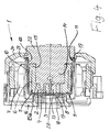
- An internal gear pump generally designated 1 has one internally toothed ring gear 2 and a meshing externally toothed within this ring gear 2 arranged impeller 3 and 2, 3, 4 and 5 a sickle 4.
- An electric one Drive of this internal gear pump 1 is formed in that the ring gear 2 the inside of a rotor 5 of a brushless Electric motor is or with the magnet 6 containing Rotor 5 is connected, this rotor 5 adjacent one Stator 7 is arranged.
- the ring gear 2 and the impeller 3 are one end face the impeller 3 and the ring gear 2 with a bottom 8 covering closed containment shell 9 shielded while whose wall area 10 which stands up relative to the floor 8 Shielding between rotor 5 and stator 7 causes.
- the whole The containment shell 9 thus encloses the essential mechanical parts the gear pump 1.
- the containment shell 9 is also in Use position with its bottom 8 and with the inside this bottom 8 axially against a journal 13 for the Impeller 3 and / or pressed against the sickle 4, so that the Gear pump on the corresponding end faces of the ring gear 2 and the impeller 3 sealed by the bottom 8 of the containment shell 9 is, but nevertheless with the appropriate dimensioning of a possibly remaining gap are easily rotatable.
- the pressures of the containment shell 9 mentioned above its bottom 8 to the journal 13 or the sickle 4 can can be effected in different ways and leads to a plane-parallel system of the plane inside of the bottom 8 on the corresponding to the flat end face of the journal 13 and / or the Sickle 4.
- a cover which can be detachably connected to the housing 16 and an intermediate piece 17 between this cover 16 and the Outside of the bottom 8 of the containment shell 9 is provided. It is also arranged in the cover 16, a pressure ring 18, the acts on the outside of the intermediate piece 17 and either itself could be resilient or something elastic intermediate piece 17 is applied.
- a flexible abutment 19 which also acts as a sealing ring, arranged in an annular groove, into the end face of the edge region 11 of the containment shell 9 intervenes somewhat in the position of use.
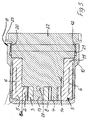
- the pressing can be done in that the containment shell has a thread on its flangeless edge region 11 20 for screwing with a centering overlapped in this case 12, so that the tightening of the thread 20 this screw connection also for pressing the bottom 8 of the containment shell 9 on the end face of the journal 13 or on the Front side of the sickle 4 is used. Pressing the can 9 with the help of the lid 16 and an intermediate piece 17 can omitted. It can be seen in FIG. 5 that in the edge region 11 of the containment shell 9 on the inside a cooperating with a housing section Sealing ring 21 is provided, which is adjacent to the centering thread 20.
- the in Fig. 5 unit shown from the essential mechanical Parts of the gear pump 1 and the containment shell 9 sealed to the outside.
- the part 22 having the centering 12 for the containment shell 9 belongs to the housing of the gear pump 1 and is in both embodiments detachably connected to the rest of the housing and interchangeable.
- this part 22 on an annular projection 23 overlapped on the outside and held with a second cover 24 is, it has a in the embodiment of FIGS. 2 and 5 Flange 25 or instead similarly shaped radial projections, overlapped with nuts 26 and with push-through screws 27 (see FIG. 2) compared to the cover 16 are fixed and thereby fix the housing part 22.
- the housing part 22 together with the containment shell 9 and its contents easily exchangeable in case the gear pump for example is worn out.
- the housing part 22 having the centering 12 is in accordance with 2 and 5 thus axially in a corresponding opening of the housing insertable and by means of flange 25 or flange-like Projections and plug screws 27 with the rest of the housing in Use position connected or connectable.
- the flangeless containment shell 9 is expediently deep-drawn, which is also possible because it has practically none Machining required to take up bearings, for example.
- the radial dimension corresponds to the end face of the containment shell 9 in the edge region at least the radial thickness the wall 10 in this edge region 11. At a distance from the free The edge of the wall 10 is reduced, so that in the area of the stator 7 this thinner wall area is arranged and affect the magnetic flux as little as possible.
- the internal gear pump 1 with an internally toothed ring gear 2 and a meshing, externally toothed impeller 3, with or without sickle, has an electric drive, which is formed by it is that the ring gear 2 the inside of a rotor 5 one especially forms brushless electric motor or with the rotor 5 is connected and that this rotor 5 is adjacent to a stator 7 is arranged.
- the ring gear 2 and the impeller 3 are one end of the impeller 3 and the ring gear 2 with a closed can 9 covering a bottom 8 opposite the stator 7 through the wall area 10 of this containment shell 9 shielded.
- This containment shell 9 is at its base 8 facing away from the bottom Edge region 11 flangeless and has a centering in particular in this edge region 11 with which the containment can 9 receives its position of use, at the same time with its bottom 8 axially against a journal 13 for the impeller 3 and / or pressed against the sickle 4, if present is that is called an edge flange for its attachment is avoided.
Landscapes
- Engineering & Computer Science (AREA)
- Mechanical Engineering (AREA)
- General Engineering & Computer Science (AREA)
- Power Engineering (AREA)
- Rotary Pumps (AREA)
- Structures Of Non-Positive Displacement Pumps (AREA)
- Details And Applications Of Rotary Liquid Pumps (AREA)
Abstract
Description
- Fig. 1
- eine Seitenansicht einer erfindungsgemäßen Innen-Zahnradpumpe,
- Fig. 2
- einen Längsschnitt der Zahnradpumpe gemäß Fig. 1,
- Fig. 3
- einen Querschnitt der Zahnradpumpe gemäß der Schnittlinie III - III in Fig. 1,
- Fig. 4
- im vergrößertem Maßstab einen Längsschnitt analog dem der Fig. 2, wobei die Befestigung des die Lagerung für Hohlrad und Laufrad aufweisenden Gehäuseteils gegenüber Fig. 2 abgewandelt ist, sowie
- Fig. 5
- in vergrößertem Maßstab die auswechselbare Einheit aus dem Gehäuseteil mit der Lagerung für Hohlrad und Laufrad und daran zentriertem Spalttopf, die gemäß Fig. 2 auswechselbar ist.
Claims (14)
- Innen-Zahnradpumpe (1) mit wenigstens einem innen verzahnten Hohlrad (2) und mit einem damit kämmenden, außen verzahnten Laufrad (3), mit oder ohne Sichel (4), und mit einem elektrischen Antrieb, der dadurch gebildet ist, dass das Hohlrad (2) das Innere eines Rotors (5) eines insbesondere bürstenlosen Elektromotors bildet oder mit dem Rotor (5) verbunden ist und dass diesem Rotor (5) benachbart ein Stator (7) angeordnet ist, wobei das Hohlrad (2) und das Laufrad (3) von einem eine Stirnseite des Laufrads (3) und des Hohlrads (2) mit einem Boden (8) überdeckenden geschlossenen Spalttopf (9) und von dessen gegenüber dem Boden (8) vorstehenden Wandbereich (10) gegenüber dem Stator (7) abgeschirmt ist, dadurch gekennzeichnet, dass der Spalttopf (9) an seinem dem Boden (8) abgewandten Randbereich (11) flanschlos ist und mit diesem Randbereich (11) eine zu dem Gehäuse der Zahnradpumpe (1) gehörende Zentrierung (12) übergreift und/oder in eine Zentrierung des Gehäuses eingreift und dass der Spalttopf (9) in Gebrauchsstellung mit seinem Boden (8) axial gegen einen Lagerzapfen (13) für das Laufrad (3) und/oder gegen die Sichel (4) angedrückt ist.
- Zahnradpumpe nach Anspruch 1, dadurch gekennzeichnet, dass das Gehäuse einen axial nach innen gerichteten, innerhalb des Spalttopfs (9) verlaufenden Zapfen (14) oder Vorsprung aufweist, der von einem das Hohlrad (2) tragenden, verzahnungsfreien Hohlzylinder (15) drehbar als Lagerstelle übergriffen ist und insbesondere einen axialen Anschlag (15a) für das Hohlrad (2) oder seinen Lagerzylinder aufweist.
- Zahnradpumpe nach Anspruch 1 oder 2, dadurch gekennzeichnet, dass der Hohlzylinder (15) Teil des Rotors (5) ist oder diesen zumindest teilweise bildet.
- Zahnradpumpe nach einem der Ansprüche 1 bis 3, dadurch gekennzeichnet, dass zum Andrücken des Spalttopfs (9) an einen Lagerzapfen (13) für das Laufrad und/oder an eine Sichel (4) ein mit dem Gehäuse insbesondere lösbar verbindbarer Deckel (16) und/oder ein Zwischenstück (17) zwischen diesem Deckel (16) und der Außenseite des Bodens (8) des Spalttopfs (9) vorgesehen ist.
- Zahnradpumpe nach einem der Ansprüche 1 bis 4, dadurch gekennzeichnet, dass an der Stirnseite des flanschlosen Randbereichs (11) des Spalttopfs (9) ein Widerlager, insbesondere ein nachgiebiges Widerlager (19) oder ein Dichtrings vorgesehen ist, welches durch das Andrücken des Spalttopfs (9) gleichzeitig zusammendrückbar ist.
- Zahnradpumpe nach einem der Ansprüche 1 bis 5, dadurch gekennzeichnet, dass der Spalttopf (9) an seinem flanschlosen Randbereich (11) ein Gewinde (20) zum Verschrauben mit einer Zentrierung aufweist und dass das Anziehen des Gewindes dieser Verschraubung auch zum Andrücken des Bodens (8) des Spalttopfs (9) an die Stirnseite des Lagerzapfens (13) des Laufrades und/oder an die Stirnseite der Sichel (4) dient.
- Zahnradpumpe nach einem der Ansprüche 1 bis 6, dadurch gekennzeichnet, dass im Randbereich (11) des Spalttopfs (9), insbesondere innenseitig ein mit einem Gehäuseabschnitt zusammenwirkender Dichtring (21) vorgesehen ist, beispielsweise benachbart zu einem Zentriergewinde.
- Zahnradpumpe nach einem der Ansprüche 1 bis 7, dadurch gekennzeichnet, dass das die Zentrierung (12) für den Spalttopf (9) aufweisende Teil (22) des Gehäuses mit dem übrigen Gehäuse der Zahnradpumpe (1) lösbar verbunden und austauschbar ist.
- Zahnradpumpe nach einem der Ansprüche 1 bis 8, dadurch gekennzeichnet, dass das die Zentrierung (12) aufweisende Gehäuseteil (22) in eine Öffnung des Gehäuses einfügbar und mittels Flansch (25) oder Bajonetteverschluss oder Gewinde oder Steckschrauben (27) mit dem übrigen Gehäuse in Gebrauchsstellung verbunden ist.
- Zahnradpumpe nach einem der Ansprüche 1 bis 9, dadurch gekennzeichnet, dass der Lagerzapfen (13) für das Laufrad (3) mit dem das Hohlrad (2) lagernden Gehäusevorsprung (14) verbunden, insbesondere einstückig verbunden ist.
- Zahnradpumpe nach einem der Ansprüche 1 bis 10, dadurch gekennzeichnet, dass der Lagervorsprung (14) des Gehäuses für das Hohlrad (2) und/oder für das Laufrad (3) zu den Lagerbereichen führende Kanäle (28) oder Bohrungen für ein Schmiermedium aufweist.
- Zahnradpumpe nach einem der Ansprüche 1 bis 11, dadurch gekennzeichnet, dass der flanschlose Spalttopf (9) tiefgezogen ist.
- Zahnradpumpe nach einem der Ansprüche 1 bis 12, dadurch gekennzeichnet, dass die radiale Abmessung der Stirnseite des Spalttopfes (9) zumindest bereichsweise der radialen Dicke dieser Wandung (10) entspricht.
- Zahnradpumpe nach einem der Ansprüche 1 bis 13, dadurch gekennzeichnet, dass die Dicke der Wandung (10) des Spalttopfes mit Abstand zu seinem freien Rand, insbesondere im Bereich des Stators (7), gegenüber der Wandstärke im randnahen Bereich vermindert ist.
Applications Claiming Priority (2)
| Application Number | Priority Date | Filing Date | Title |
|---|---|---|---|
| DE10248933A DE10248933C1 (de) | 2002-10-19 | 2002-10-19 | Innen-Zahnradpumpe mit einem verzahnten Hohlrad und einem damit kämmenden Laufrad |
| DE10248933 | 2002-10-19 |
Publications (3)
| Publication Number | Publication Date |
|---|---|
| EP1411246A2 true EP1411246A2 (de) | 2004-04-21 |
| EP1411246A3 EP1411246A3 (de) | 2004-11-17 |
| EP1411246B1 EP1411246B1 (de) | 2005-09-28 |
Family
ID=29432758
Family Applications (1)
| Application Number | Title | Priority Date | Filing Date |
|---|---|---|---|
| EP03014014A Expired - Lifetime EP1411246B1 (de) | 2002-10-19 | 2003-06-21 | Innenzahnradpumpe mit einem verzahnten Hohlrad und einem damit kämmenden Laufrad |
Country Status (3)
| Country | Link |
|---|---|
| EP (1) | EP1411246B1 (de) |
| AT (1) | ATE305566T1 (de) |
| DE (2) | DE10248933C1 (de) |
Cited By (3)
| Publication number | Priority date | Publication date | Assignee | Title |
|---|---|---|---|---|
| US7786634B2 (en) | 2004-07-27 | 2010-08-31 | Gas Power Energy Ab | Motor- or a generator-related arrangement |
| CN109563830A (zh) * | 2016-08-09 | 2019-04-02 | 日本电产株式会社 | 驱动装置 |
| KR20200099191A (ko) * | 2017-12-22 | 2020-08-21 | 한온 시스템즈 이에프피 도이칠란드 게엠베하 | 지로터 펌프 및 그의 제조 방법 |
Families Citing this family (3)
| Publication number | Priority date | Publication date | Assignee | Title |
|---|---|---|---|---|
| DE102007035239A1 (de) | 2007-07-25 | 2009-01-29 | Joma-Hydromechanic Gmbh | Rotorpumpe |
| DE102009028148A1 (de) * | 2009-07-31 | 2011-02-03 | Robert Bosch Gmbh | Zahnradpumpe |
| DE102013018159A1 (de) * | 2013-12-05 | 2015-06-11 | Klaus Union Gmbh & Co. Kg | Spalttopf und Verfahren zur Herstellung desselben |
Citations (4)
| Publication number | Priority date | Publication date | Assignee | Title |
|---|---|---|---|---|
| JPS6081488A (ja) * | 1983-10-13 | 1985-05-09 | Honda Motor Co Ltd | ポンプ装置 |
| DE3943369A1 (de) * | 1989-12-30 | 1991-07-11 | Fresenius Ag | Zahnradpumpe, insbesondere gekapselte medizinische zahnradpumpe |
| DE29913367U1 (de) * | 1999-07-30 | 1999-12-09 | Pumpenfabrik Ernst Scherzinger GmbH & Co. KG, 78120 Furtwangen | Innen-Zahnradpumpe, deren Hohlrad das Innere eines Rotors eines Elektromotors ist |
| USH1966H1 (en) * | 1997-08-28 | 2001-06-05 | The United States Of America As Represented By The Secretary Of The Navy | Integrated motor/gear pump |
Family Cites Families (2)
| Publication number | Priority date | Publication date | Assignee | Title |
|---|---|---|---|---|
| US2711286A (en) * | 1952-08-01 | 1955-06-21 | Wetmore Hodges | Motor-pump or compressor |
| DE4106060C2 (de) * | 1991-02-27 | 1995-11-30 | Fresenius Ag | Pumpe, insbesondere gekapselte medizinische Pumpe |
-
2002
- 2002-10-19 DE DE10248933A patent/DE10248933C1/de not_active Expired - Fee Related
-
2003
- 2003-06-21 EP EP03014014A patent/EP1411246B1/de not_active Expired - Lifetime
- 2003-06-21 DE DE50301254T patent/DE50301254D1/de not_active Expired - Lifetime
- 2003-06-21 AT AT03014014T patent/ATE305566T1/de not_active IP Right Cessation
Patent Citations (4)
| Publication number | Priority date | Publication date | Assignee | Title |
|---|---|---|---|---|
| JPS6081488A (ja) * | 1983-10-13 | 1985-05-09 | Honda Motor Co Ltd | ポンプ装置 |
| DE3943369A1 (de) * | 1989-12-30 | 1991-07-11 | Fresenius Ag | Zahnradpumpe, insbesondere gekapselte medizinische zahnradpumpe |
| USH1966H1 (en) * | 1997-08-28 | 2001-06-05 | The United States Of America As Represented By The Secretary Of The Navy | Integrated motor/gear pump |
| DE29913367U1 (de) * | 1999-07-30 | 1999-12-09 | Pumpenfabrik Ernst Scherzinger GmbH & Co. KG, 78120 Furtwangen | Innen-Zahnradpumpe, deren Hohlrad das Innere eines Rotors eines Elektromotors ist |
Non-Patent Citations (1)
| Title |
|---|
| PATENT ABSTRACTS OF JAPAN Bd. 0092, Nr. 23 (M-411), 10. September 1985 (1985-09-10) & JP 60 081488 A (HONDA GIKEN KOGYO KK), 9. Mai 1985 (1985-05-09) * |
Cited By (4)
| Publication number | Priority date | Publication date | Assignee | Title |
|---|---|---|---|---|
| US7786634B2 (en) | 2004-07-27 | 2010-08-31 | Gas Power Energy Ab | Motor- or a generator-related arrangement |
| CN109563830A (zh) * | 2016-08-09 | 2019-04-02 | 日本电产株式会社 | 驱动装置 |
| CN109563830B (zh) * | 2016-08-09 | 2020-06-09 | 日本电产株式会社 | 驱动装置 |
| KR20200099191A (ko) * | 2017-12-22 | 2020-08-21 | 한온 시스템즈 이에프피 도이칠란드 게엠베하 | 지로터 펌프 및 그의 제조 방법 |
Also Published As
| Publication number | Publication date |
|---|---|
| EP1411246B1 (de) | 2005-09-28 |
| EP1411246A3 (de) | 2004-11-17 |
| ATE305566T1 (de) | 2005-10-15 |
| DE50301254D1 (de) | 2006-02-09 |
| DE10248933C1 (de) | 2003-12-11 |
Similar Documents
| Publication | Publication Date | Title |
|---|---|---|
| DE29913367U1 (de) | Innen-Zahnradpumpe, deren Hohlrad das Innere eines Rotors eines Elektromotors ist | |
| DE4315826B4 (de) | Motor-Pumpen-Aggregat | |
| DE4331560B4 (de) | Magnetisch gekuppelte Kreiselpumpe | |
| DE2554105C2 (de) | Zahnradmaschine (Pumpe oder Motor) | |
| DE102012001700A1 (de) | Zweispindelige Schraubenspindelpumpe in einflutiger Bauweise | |
| DE4412928A1 (de) | Hydraulisch betätigbare Vorrichtung zum Ausrücken einer Schalttrennkupplung eines Kraftfahrzeugs | |
| DE3620705A1 (de) | Innenzahnradpumpe als schmieroelpumpe | |
| DE102015011888A1 (de) | Fahrzeug-Antriebsvorrichtung | |
| EP1859170A1 (de) | Drehkolbenmaschine | |
| DE4102932C2 (de) | Getriebemotor | |
| EP1411246B1 (de) | Innenzahnradpumpe mit einem verzahnten Hohlrad und einem damit kämmenden Laufrad | |
| DE102016207093A1 (de) | Zahnradfluidmaschine | |
| DE102008014379A1 (de) | Elektromechanische Maschine | |
| DE8208734U1 (de) | Zahnradpumpe | |
| DE3616672C2 (de) | ||
| EP0405002A1 (de) | Elektrischer Aussenläufermotor | |
| EP0918932B1 (de) | Elektromotor-/pumpenaggregat | |
| DE102015007521B4 (de) | Pumpengehäuse für eine Exzenterschneckenpumpe und damit ausgestattete Exzenterschneckenpumpe | |
| DE8128186U1 (de) | Getriebemotor, insbesondere elektromotorischer fensterheber-antrieb fuer kraftfahrzeuge | |
| DE3136132C2 (de) | Zentraldrehkupplung | |
| EP0297147B1 (de) | Innenzahnradpumpe als Schmierölpumpe | |
| DE102011082012A1 (de) | Antriebsvorrichtung | |
| DE102008043569B4 (de) | Motorbaugruppe für Fensterheberanwendungen | |
| DE102008000728A1 (de) | Handwerkzeugmaschine, insbesondere handgeführte Schleifmaschine | |
| DE3545886C2 (de) |
Legal Events
| Date | Code | Title | Description |
|---|---|---|---|
| PUAI | Public reference made under article 153(3) epc to a published international application that has entered the european phase |
Free format text: ORIGINAL CODE: 0009012 |
|
| AK | Designated contracting states |
Kind code of ref document: A2 Designated state(s): AT BE BG CH CY CZ DE DK EE ES FI FR GB GR HU IE IT LI LU MC NL PT RO SE SI SK TR |
|
| AX | Request for extension of the european patent |
Extension state: AL LT LV MK |
|
| PUAL | Search report despatched |
Free format text: ORIGINAL CODE: 0009013 |
|
| AK | Designated contracting states |
Kind code of ref document: A3 Designated state(s): AT BE BG CH CY CZ DE DK EE ES FI FR GB GR HU IE IT LI LU MC NL PT RO SE SI SK TR |
|
| AX | Request for extension of the european patent |
Extension state: AL LT LV MK |
|
| RIC1 | Information provided on ipc code assigned before grant |
Ipc: 7F 04C 15/00 B Ipc: 7F 04C 2/08 B Ipc: 7F 04C 2/10 A |
|
| 17P | Request for examination filed |
Effective date: 20050119 |
|
| GRAP | Despatch of communication of intention to grant a patent |
Free format text: ORIGINAL CODE: EPIDOSNIGR1 |
|
| AKX | Designation fees paid |
Designated state(s): AT BE BG CH CY CZ DE DK EE ES FI FR GB GR HU IE IT LI LU MC NL PT RO SE SI SK TR |
|
| GRAS | Grant fee paid |
Free format text: ORIGINAL CODE: EPIDOSNIGR3 |
|
| GRAA | (expected) grant |
Free format text: ORIGINAL CODE: 0009210 |
|
| AK | Designated contracting states |
Kind code of ref document: B1 Designated state(s): AT BE BG CH CY CZ DE DK EE ES FI FR GB GR HU IE IT LI LU MC NL PT RO SE SI SK TR |
|
| PG25 | Lapsed in a contracting state [announced via postgrant information from national office to epo] |
Ref country code: IT Free format text: LAPSE BECAUSE OF FAILURE TO SUBMIT A TRANSLATION OF THE DESCRIPTION OR TO PAY THE FEE WITHIN THE PRESCRIBED TIME-LIMIT;WARNING: LAPSES OF ITALIAN PATENTS WITH EFFECTIVE DATE BEFORE 2007 MAY HAVE OCCURRED AT ANY TIME BEFORE 2007. THE CORRECT EFFECTIVE DATE MAY BE DIFFERENT FROM THE ONE RECORDED. Effective date: 20050928 Ref country code: CZ Free format text: LAPSE BECAUSE OF FAILURE TO SUBMIT A TRANSLATION OF THE DESCRIPTION OR TO PAY THE FEE WITHIN THE PRESCRIBED TIME-LIMIT Effective date: 20050928 Ref country code: SK Free format text: LAPSE BECAUSE OF FAILURE TO SUBMIT A TRANSLATION OF THE DESCRIPTION OR TO PAY THE FEE WITHIN THE PRESCRIBED TIME-LIMIT Effective date: 20050928 Ref country code: RO Free format text: LAPSE BECAUSE OF FAILURE TO SUBMIT A TRANSLATION OF THE DESCRIPTION OR TO PAY THE FEE WITHIN THE PRESCRIBED TIME-LIMIT Effective date: 20050928 Ref country code: IE Free format text: LAPSE BECAUSE OF FAILURE TO SUBMIT A TRANSLATION OF THE DESCRIPTION OR TO PAY THE FEE WITHIN THE PRESCRIBED TIME-LIMIT Effective date: 20050928 Ref country code: SI Free format text: LAPSE BECAUSE OF FAILURE TO SUBMIT A TRANSLATION OF THE DESCRIPTION OR TO PAY THE FEE WITHIN THE PRESCRIBED TIME-LIMIT Effective date: 20050928 Ref country code: NL Free format text: LAPSE BECAUSE OF FAILURE TO SUBMIT A TRANSLATION OF THE DESCRIPTION OR TO PAY THE FEE WITHIN THE PRESCRIBED TIME-LIMIT Effective date: 20050928 Ref country code: FI Free format text: LAPSE BECAUSE OF FAILURE TO SUBMIT A TRANSLATION OF THE DESCRIPTION OR TO PAY THE FEE WITHIN THE PRESCRIBED TIME-LIMIT Effective date: 20050928 |
|
| REG | Reference to a national code |
Ref country code: GB Ref legal event code: FG4D Free format text: NOT ENGLISH |
|
| REG | Reference to a national code |
Ref country code: CH Ref legal event code: EP |
|
| REG | Reference to a national code |
Ref country code: IE Ref legal event code: FG4D Free format text: LANGUAGE OF EP DOCUMENT: GERMAN |
|
| PG25 | Lapsed in a contracting state [announced via postgrant information from national office to epo] |
Ref country code: BG Free format text: LAPSE BECAUSE OF FAILURE TO SUBMIT A TRANSLATION OF THE DESCRIPTION OR TO PAY THE FEE WITHIN THE PRESCRIBED TIME-LIMIT Effective date: 20051228 Ref country code: SE Free format text: LAPSE BECAUSE OF FAILURE TO SUBMIT A TRANSLATION OF THE DESCRIPTION OR TO PAY THE FEE WITHIN THE PRESCRIBED TIME-LIMIT Effective date: 20051228 Ref country code: DK Free format text: LAPSE BECAUSE OF FAILURE TO SUBMIT A TRANSLATION OF THE DESCRIPTION OR TO PAY THE FEE WITHIN THE PRESCRIBED TIME-LIMIT Effective date: 20051228 Ref country code: GR Free format text: LAPSE BECAUSE OF FAILURE TO SUBMIT A TRANSLATION OF THE DESCRIPTION OR TO PAY THE FEE WITHIN THE PRESCRIBED TIME-LIMIT Effective date: 20051228 |
|
| PG25 | Lapsed in a contracting state [announced via postgrant information from national office to epo] |
Ref country code: ES Free format text: LAPSE BECAUSE OF FAILURE TO SUBMIT A TRANSLATION OF THE DESCRIPTION OR TO PAY THE FEE WITHIN THE PRESCRIBED TIME-LIMIT Effective date: 20060108 |
|
| GBT | Gb: translation of ep patent filed (gb section 77(6)(a)/1977) |
Effective date: 20060112 |
|
| REF | Corresponds to: |
Ref document number: 50301254 Country of ref document: DE Date of ref document: 20060209 Kind code of ref document: P |
|
| PG25 | Lapsed in a contracting state [announced via postgrant information from national office to epo] |
Ref country code: PT Free format text: LAPSE BECAUSE OF FAILURE TO SUBMIT A TRANSLATION OF THE DESCRIPTION OR TO PAY THE FEE WITHIN THE PRESCRIBED TIME-LIMIT Effective date: 20060228 |
|
| NLV1 | Nl: lapsed or annulled due to failure to fulfill the requirements of art. 29p and 29m of the patents act | ||
| PG25 | Lapsed in a contracting state [announced via postgrant information from national office to epo] |
Ref country code: HU Free format text: LAPSE BECAUSE OF FAILURE TO SUBMIT A TRANSLATION OF THE DESCRIPTION OR TO PAY THE FEE WITHIN THE PRESCRIBED TIME-LIMIT Effective date: 20060329 |
|
| ET | Fr: translation filed | ||
| REG | Reference to a national code |
Ref country code: IE Ref legal event code: FD4D |
|
| PG25 | Lapsed in a contracting state [announced via postgrant information from national office to epo] |
Ref country code: BE Free format text: LAPSE BECAUSE OF NON-PAYMENT OF DUE FEES Effective date: 20060630 Ref country code: MC Free format text: LAPSE BECAUSE OF NON-PAYMENT OF DUE FEES Effective date: 20060630 |
|
| PLBE | No opposition filed within time limit |
Free format text: ORIGINAL CODE: 0009261 |
|
| STAA | Information on the status of an ep patent application or granted ep patent |
Free format text: STATUS: NO OPPOSITION FILED WITHIN TIME LIMIT |
|
| 26N | No opposition filed |
Effective date: 20060629 |
|
| REG | Reference to a national code |
Ref country code: FR Ref legal event code: ST Effective date: 20070228 |
|
| PG25 | Lapsed in a contracting state [announced via postgrant information from national office to epo] |
Ref country code: AT Free format text: LAPSE BECAUSE OF NON-PAYMENT OF DUE FEES Effective date: 20060621 |
|
| BERE | Be: lapsed |
Owner name: PUMPENFABRIK ERNST SCHERZINGER G.M.B.H. & CO. KG Effective date: 20060630 |
|
| REG | Reference to a national code |
Ref country code: CH Ref legal event code: PL |
|
| PG25 | Lapsed in a contracting state [announced via postgrant information from national office to epo] |
Ref country code: FR Free format text: LAPSE BECAUSE OF NON-PAYMENT OF DUE FEES Effective date: 20060630 Ref country code: LI Free format text: LAPSE BECAUSE OF NON-PAYMENT OF DUE FEES Effective date: 20070630 Ref country code: CH Free format text: LAPSE BECAUSE OF NON-PAYMENT OF DUE FEES Effective date: 20070630 |
|
| PG25 | Lapsed in a contracting state [announced via postgrant information from national office to epo] |
Ref country code: EE Free format text: LAPSE BECAUSE OF FAILURE TO SUBMIT A TRANSLATION OF THE DESCRIPTION OR TO PAY THE FEE WITHIN THE PRESCRIBED TIME-LIMIT Effective date: 20050928 |
|
| PG25 | Lapsed in a contracting state [announced via postgrant information from national office to epo] |
Ref country code: TR Free format text: LAPSE BECAUSE OF FAILURE TO SUBMIT A TRANSLATION OF THE DESCRIPTION OR TO PAY THE FEE WITHIN THE PRESCRIBED TIME-LIMIT Effective date: 20050928 Ref country code: LU Free format text: LAPSE BECAUSE OF NON-PAYMENT OF DUE FEES Effective date: 20060621 |
|
| PG25 | Lapsed in a contracting state [announced via postgrant information from national office to epo] |
Ref country code: CY Free format text: LAPSE BECAUSE OF FAILURE TO SUBMIT A TRANSLATION OF THE DESCRIPTION OR TO PAY THE FEE WITHIN THE PRESCRIBED TIME-LIMIT Effective date: 20050928 |
|
| PGFP | Annual fee paid to national office [announced via postgrant information from national office to epo] |
Ref country code: DE Payment date: 20100428 Year of fee payment: 8 Ref country code: GB Payment date: 20100614 Year of fee payment: 8 |
|
| GBPC | Gb: european patent ceased through non-payment of renewal fee |
Effective date: 20110621 |
|
| PG25 | Lapsed in a contracting state [announced via postgrant information from national office to epo] |
Ref country code: DE Free format text: LAPSE BECAUSE OF NON-PAYMENT OF DUE FEES Effective date: 20120103 |
|
| REG | Reference to a national code |
Ref country code: DE Ref legal event code: R119 Ref document number: 50301254 Country of ref document: DE Effective date: 20120103 |
|
| PG25 | Lapsed in a contracting state [announced via postgrant information from national office to epo] |
Ref country code: GB Free format text: LAPSE BECAUSE OF NON-PAYMENT OF DUE FEES Effective date: 20110621 |