EP1411194B1 - Vehicle door lock - Google Patents
Vehicle door lock Download PDFInfo
- Publication number
- EP1411194B1 EP1411194B1 EP20030020658 EP03020658A EP1411194B1 EP 1411194 B1 EP1411194 B1 EP 1411194B1 EP 20030020658 EP20030020658 EP 20030020658 EP 03020658 A EP03020658 A EP 03020658A EP 1411194 B1 EP1411194 B1 EP 1411194B1
- Authority
- EP
- European Patent Office
- Prior art keywords
- adjustment element
- adjustment
- slotted guide
- switching lever
- vehicle door
- Prior art date
- Legal status (The legal status is an assumption and is not a legal conclusion. Google has not performed a legal analysis and makes no representation as to the accuracy of the status listed.)
- Expired - Fee Related
Links
Images


Classifications
-
- E—FIXED CONSTRUCTIONS
- E05—LOCKS; KEYS; WINDOW OR DOOR FITTINGS; SAFES
- E05B—LOCKS; ACCESSORIES THEREFOR; HANDCUFFS
- E05B81/00—Power-actuated vehicle locks
- E05B81/02—Power-actuated vehicle locks characterised by the type of actuators used
- E05B81/04—Electrical
- E05B81/06—Electrical using rotary motors
-
- E—FIXED CONSTRUCTIONS
- E05—LOCKS; KEYS; WINDOW OR DOOR FITTINGS; SAFES
- E05B—LOCKS; ACCESSORIES THEREFOR; HANDCUFFS
- E05B81/00—Power-actuated vehicle locks
- E05B81/12—Power-actuated vehicle locks characterised by the function or purpose of the powered actuators
- E05B81/16—Power-actuated vehicle locks characterised by the function or purpose of the powered actuators operating on locking elements for locking or unlocking action
-
- E—FIXED CONSTRUCTIONS
- E05—LOCKS; KEYS; WINDOW OR DOOR FITTINGS; SAFES
- E05B—LOCKS; ACCESSORIES THEREFOR; HANDCUFFS
- E05B81/00—Power-actuated vehicle locks
- E05B81/24—Power-actuated vehicle locks characterised by constructional features of the actuator or the power transmission
- E05B81/32—Details of the actuator transmission
- E05B81/42—Cams
- E05B81/44—Cams in the form of grooves
-
- E—FIXED CONSTRUCTIONS
- E05—LOCKS; KEYS; WINDOW OR DOOR FITTINGS; SAFES
- E05B—LOCKS; ACCESSORIES THEREFOR; HANDCUFFS
- E05B81/00—Power-actuated vehicle locks
- E05B81/54—Electrical circuits
- E05B81/56—Control of actuators
- E05B81/62—Control of actuators for opening or closing of a circuit depending on electrical parameters, e.g. increase of motor current
-
- E—FIXED CONSTRUCTIONS
- E05—LOCKS; KEYS; WINDOW OR DOOR FITTINGS; SAFES
- E05B—LOCKS; ACCESSORIES THEREFOR; HANDCUFFS
- E05B81/00—Power-actuated vehicle locks
- E05B81/54—Electrical circuits
- E05B81/90—Manual override in case of power failure
-
- Y—GENERAL TAGGING OF NEW TECHNOLOGICAL DEVELOPMENTS; GENERAL TAGGING OF CROSS-SECTIONAL TECHNOLOGIES SPANNING OVER SEVERAL SECTIONS OF THE IPC; TECHNICAL SUBJECTS COVERED BY FORMER USPC CROSS-REFERENCE ART COLLECTIONS [XRACs] AND DIGESTS
- Y10—TECHNICAL SUBJECTS COVERED BY FORMER USPC
- Y10S—TECHNICAL SUBJECTS COVERED BY FORMER USPC CROSS-REFERENCE ART COLLECTIONS [XRACs] AND DIGESTS
- Y10S292/00—Closure fasteners
- Y10S292/23—Vehicle door latches
-
- Y—GENERAL TAGGING OF NEW TECHNOLOGICAL DEVELOPMENTS; GENERAL TAGGING OF CROSS-SECTIONAL TECHNOLOGIES SPANNING OVER SEVERAL SECTIONS OF THE IPC; TECHNICAL SUBJECTS COVERED BY FORMER USPC CROSS-REFERENCE ART COLLECTIONS [XRACs] AND DIGESTS
- Y10—TECHNICAL SUBJECTS COVERED BY FORMER USPC
- Y10T—TECHNICAL SUBJECTS COVERED BY FORMER US CLASSIFICATION
- Y10T292/00—Closure fasteners
- Y10T292/08—Bolts
- Y10T292/096—Sliding
- Y10T292/1014—Operating means
- Y10T292/1021—Motor
-
- Y—GENERAL TAGGING OF NEW TECHNOLOGICAL DEVELOPMENTS; GENERAL TAGGING OF CROSS-SECTIONAL TECHNOLOGIES SPANNING OVER SEVERAL SECTIONS OF THE IPC; TECHNICAL SUBJECTS COVERED BY FORMER USPC CROSS-REFERENCE ART COLLECTIONS [XRACs] AND DIGESTS
- Y10—TECHNICAL SUBJECTS COVERED BY FORMER USPC
- Y10T—TECHNICAL SUBJECTS COVERED BY FORMER US CLASSIFICATION
- Y10T292/00—Closure fasteners
- Y10T292/08—Bolts
- Y10T292/1043—Swinging
- Y10T292/1044—Multiple head
- Y10T292/1045—Operating means
- Y10T292/1047—Closure
-
- Y—GENERAL TAGGING OF NEW TECHNOLOGICAL DEVELOPMENTS; GENERAL TAGGING OF CROSS-SECTIONAL TECHNOLOGIES SPANNING OVER SEVERAL SECTIONS OF THE IPC; TECHNICAL SUBJECTS COVERED BY FORMER USPC CROSS-REFERENCE ART COLLECTIONS [XRACs] AND DIGESTS
- Y10—TECHNICAL SUBJECTS COVERED BY FORMER USPC
- Y10T—TECHNICAL SUBJECTS COVERED BY FORMER US CLASSIFICATION
- Y10T292/00—Closure fasteners
- Y10T292/08—Bolts
- Y10T292/1043—Swinging
- Y10T292/1075—Operating means
- Y10T292/1082—Motor
Description
Die vorliegende Erfindung betrifft ein Kraftfahrzeug-Türschloß mit den Merkmalen des Oberbegriffs von Anspruch 1 sowie ein Stellelement für ein Kraftfahrzeug-Türschloß mit den Merkmalen des Oberbegriffs von Anspruch 9. Vorliegend sind unter dem Begriff Kraftfahrzeug-Türschloß alle Arten von Tür-, Hauben- oder Klappenschlössern zusammengefaßt.The present invention relates to a motor vehicle door lock with the features of the preamble of
Nachteilig bei bekannten Kraftfahrzeug-Türschlössern ist die Tatsache, daß die leichte manuelle Verstellbarkeit des Schalthebels durch einen vergleichsweise langen und damit zeitaufwendigen anfänglichen Freilauf des Stellelements bei der Entriegelung erkauft wird. Es ist nämlich so, daß bei der motorischen Verstellung des Schalthebels das Stellelement bzw. der Zapfen in der Kulissenfuhrung des Stellelements zunächst den aufgeweiteten Teil der Kulissenführung durchlaufen muß, um in den kanalförmigen Bereich der Kulissenführung zu gelangen, so daß eine entsprechende Kraftwirkung auf den Schalthebel möglich ist.A disadvantage of known motor vehicle door locks is the fact that the slight manual adjustability of the shift lever is paid for by a comparatively long and thus time-consuming initial freewheeling of the actuating element during unlocking. It is such that in the motorized adjustment of the shift lever, the actuator or the pin in the Kulissenfuhrung of the actuating element must first pass through the expanded part of the slotted guide to get into the channel-shaped region of the slotted guide, so that a corresponding force on the shift lever is possible.
Die zuvor aufgezeigte Problemstellung ist bereits erkannt und behandelt worden (
Bei diesem bekannten Kraftfahrzeug-Türschloß ist die Konstruktion von Antrieb und Stellelement so gewählt, daß einem Schaltzustand des Schalthebels mindestens zwei, dort in verschiedenen Ausführungsbeispielen zwei oder vier hinsichtlich der Wirkung des Stellelementes auf den Schalthebel gleichwertige Stellungen des Stellelementes zugeordnet sind. Das Verhalten des in verschiedenen Stellungen befindlichen Stellelementes gegenüber dem Schalthebel ist nicht nur in der jeweiligen Stellung selbst, sondern auch bei einer Verstellung aus der jeweiligen Stellung heraus jeweils identisch.In this known motor vehicle door lock, the construction of drive and control element is chosen so that a switching state of the lever at least two, there are assigned in different embodiments two or four with respect to the effect of the control element on the shift lever equivalent positions of the control element. The behavior of the control element located in different positions relative to the shift lever is identical not only in the respective position itself, but also in an adjustment from the respective position.
Damit läßt sich ein langer Freilauf des Stellelements bis zum Erreichen einer bestimmten Stellung vermeiden, da diese bestimmte Stellung bei der symmetrischen Ausgestaltung über den Verstellbereich des Stellelements gesehen mehrfach vorliegt. Besonders vorteilhaft ist es, wenn die Verstellung des Stellelements aus einer Ausgangsstellung heraus in einer weiteren, gleichwertigen Ausgangsstellung endet.Thus, a long freewheeling of the actuator can be avoided until reaching a certain position, as this particular position in the symmetrical Embodiment over the adjustment of the control element seen multiple times. It is particularly advantageous if the adjustment of the actuating element ends in a further, equivalent starting position from an initial position.
Für die manuelle Verstellbarkeit des Schalthebels insbesondere im Fehlerfall ist die symmetrische Ausgestaltung des Stellelements von besonderem Vorteil. In einem solchen Fall kommt das Stellelement inmitten der Verstellbewegung aus einer Ausgangsstellung heraus, beispielsweise durch den Ausfall des Motors, zu stehen. Bei symmetrischer Ausgestaltung des Stellelements kann hier grundsätzlich vorgesehen werden, durch eine manuelle Verstellung des Schalthebels das Stellelement in die "nächstliegende" Ausgangsstellung zu verstellen.For the manual adjustability of the shift lever, in particular in the event of a fault, the symmetrical design of the actuating element is of particular advantage. In such a case, the actuator comes in the middle of the adjustment of an initial position out, for example, by the failure of the engine to stand. In the case of a symmetrical design of the control element, it is fundamentally possible to adjust the control element to the "closest" starting position by manual adjustment of the control lever.
Bei dem bekannten, zuvor erläuterten Kraftfahrzeug-Türschloß, von dem die Erfindung ausgeht, ist weiter eine manuelle Verstellung des Schalthebels vom ersten in den zweiten Schaltzustand und umgekehrt ohne Verstellung des Stellelements bei in der Ausgangsstellung befindlichem Stellelement möglich. Das Stellelement ist um eine Achse drehbar und eine Stellung des Stellelementes ist der entsprechend gedrehten Stellung gleichwertig.In the known, previously explained motor vehicle door lock, from which the invention proceeds, is further a manual adjustment of the shift lever from the first to the second switching state and vice versa possible without adjustment of the actuating element befindlichem in the starting position actuator. The adjusting element is rotatable about an axis and a position of the adjusting element is equivalent to the corresponding rotated position.
Bei dem bekannten Kraftfahrzeug-Türschloß weist das Stellelement eine Kulissenführung und der Schalthebel einen in die Kulissenführung eingreifenden Zapfen auf. Die Kulissenführung hat eine der Anzahl der Ausgangsstellungen entsprechende Anzahl von Kulissenabschnitten. Je zwei Kulissenabschnitte sind über einen kurzen, radial verlaufenden Querabschnitt miteinander verbunden. In diesem Querabschnitt kann die Verstellung des Schalthebels manuell von der ersten in die zweite Schaltstellung und umgekehrt ohne Verstellung des Stellelements erfolgen. Blockiert der Antrieb in einer Stellung, in der sich der Zapfen gerade in einer der viertelkreisförmigen Kulissenabschnitte befindet, so ist eine manuelle Verstellung des Schalthebels zwar ebenfalls möglich, jedoch schwieriger. Der Zapfen kann nämlich im Kulissenabschnitt aufgrund dessen Formgebung nur in einer Richtung weiterbewegt werden. Ggf. wird der eigentlich gewünschte Schaltzustand nur über den zunächst nicht gewünschten Schaltzustand und ein anschließendes Rückschalten im radial verlaufenden Querabschnitt erreicht.In the known motor vehicle door lock, the actuator has a slotted guide and the shift lever engaging in the slotted guide pin. The slide guide has a number of starting positions corresponding number of slide sections. Two link sections are connected to each other via a short, radially extending transverse section. In this cross section, the adjustment of the shift lever can be done manually from the first to the second switching position and vice versa without adjustment of the actuating element. Blocked the drive in a position in which the pin is currently located in one of the quarter-circular link sections, a manual adjustment of the shift lever is also possible, but more difficult. The pin can namely be moved in the gate section due to its shape only in one direction. Possibly. the actually desired switching state is achieved only via the initially undesirable switching state and a subsequent switching back in the radially extending transverse section.
Das bekannte Kraftfahrzeug-Türschloß weist im übrigen noch eine zusätzliche Konstruktion mit einem Freilaufelement auf. Das Freilaufelement ist mit dem Stellelement mittels einer Freilaufverbindung verbunden. Dadurch ist es möglich, eine Verstellung des Schalthebels manuell und unter Verstellung des Stellelementes zu bewirken, obwohl der Antrieb selbst an sich selbsthemmend ist.The well-known motor vehicle door lock has, moreover, an additional construction with a freewheeling element. The freewheeling element is connected to the actuating element by means of a freewheeling connection. This makes it possible to effect an adjustment of the shift lever manually and under adjustment of the actuating element, although the drive itself is self-locking in itself.
Von der zuvor erläuterten bekannten Konstruktion ausgehend liegt der Lehre das Problem zugrunde, das Kraftfahrzeug-Türschloß so auszugestalten und weiterzubilden, daß die manuelle Verstellbarkeit des Schalthebels mit minimalem Bewegungsweg und Zeitaufwand gewährleistet ist.Starting from the above-described known construction, the teaching is based on the problem of designing and further developing the motor vehicle door lock in such a way that the manual adjustability of the shift lever is ensured with minimal movement path and expenditure of time.
Das zuvor aufgezeigte Problem wird durch ein Kraftfahrzeug-Türschloß gemäß dem Oberbegriff von Anspruch 1 mit den Merkmalen des kennzeichnenden Teils von Anspruch 1 gelöst.The above-identified problem is solved by a motor vehicle door lock according to the preamble of
Bei dem den Ausgangspunkt bildenden Kraftfahrzeug-Türschloß ist die zuvor erläuterte, vom Bewegungsweg her aufwendige manuelle Verstellung ursächlich damit verbunden, daß die Kulissenabschnitte auch gleichzeitig, nämlich am radial verlaufenden Querabschnitt, jeweils die Anschläge für die Drehbewegung des Stellelementes bilden. Hier setzt die Lösung der zuvor erörterten Problemstellung an, die Gegenstand des Anspruchs 1 ist.In the motor vehicle door lock forming the starting point, the above-described manual adjustment, which is complicated by the movement path, is causally linked to the fact that the slide sections simultaneously also form the stops for the rotary movement of the control element, namely at the radially extending transverse section. This is where the solution to the above-discussed problem, which is the subject of
Bevorzugte Ausgestaltungen und Weiterbildungen der zuvor erläuterten Lehre sind Gegenstand der Ansprüche 2 bis 8.Preferred embodiments and further developments of the teaching explained above are the subject matter of
Die Realisierung eines Wendepunktes zwischen den Kulissenabschnitten gemäß Anspruch 3 macht es möglich, auf dem kürzesten Weg in die jeweils wirklich "nächstliegende" Ausgangsstellung zu gelangen.The realization of a turning point between the gate sections according to
Nach einer weiteren Lehre, der ebenfalls eigenständige Bedeutung zukommt, wird das Stellelement eines Kraftfahrzeug-Türschlosses als solches, wie oben beschrieben beansprucht. Auf die obigen Ausführungen darf verwiesen werden.According to another teaching, which also has independent significance, the actuator of a motor vehicle door lock is claimed as such, as described above. Reference may be made to the above statements.
Im folgenden wird die Erfindung anhand einer lediglich ein Ausführungsbeispiel darstellenden Zeichnung näher erläutert. In der Zeichnung zeigt
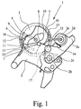
- Fig. 1
- ein bevorzugtes Ausführungsbeispiel eines erfindungsgemäßen Kraftfahrzeug-Türschlosses in einem ersten Schaltzustand, beispielsweise dem verriegelten Zustand,
- Fig. 2
- das Kraftfahrzeug-Türschloß aus
Fig. 1 in einem Zwischenzustand vor Erreichen eines Wendepunkts, - Fig. 3
- das Kraftfahrzeug-Türschloß aus
Fig. 1 in einem zweiten Schaltzustand, beispielsweise dem entriegelten Zustand.
- Fig. 1
- A preferred embodiment of a motor vehicle door lock according to the invention in a first switching state, for example, the locked state,
- Fig. 2
- the motor vehicle door lock
Fig. 1 in an intermediate state before reaching a turning point, - Fig. 3
- the motor vehicle door lock
Fig. 1 in a second switching state, for example the unlocked state.
Das ansonsten nicht weiter dargestellte Kraftfahrzeug-Türschloß weist die üblichen Schließelemente wie Schloßfalle und Sperrklinke sowie eine Schloßmechanik mit der Zentralverriegelungsanordnung 1 auf. Für die Gestaltung eines Beispiels eines solchen Kraftfahrzeug-Türschlosses hinsichtlich Schloßfalle und Sperrklinke sowie Schloßmechanik darf auf die eingangs erläuterte
Die Zentralverriegelungsanordnung 1 beinhaltet einen Antrieb und einen Schalthebel 2, wobei der Antrieb einen nicht weiter dargestellten Motor und ein Stellelement 3 aufweist. Der Schalthebel 2 ist durch den Antrieb in verschiedene Schaltzustände, vorliegend in den entriegelten Zustand und in den dargestellten verriegelten Zustand, bringbar. Es kann auch sein, daß der Schalthebel 2 in mehrere Schaltzustände bringbar ist. Für die Verstellung des Schalthebels 2 durch den Antrieb ist das Stellelement 3 mit dem Schalthebel 2 in Eingriff bringbar, wie im folgenden gezeigt wird.The
Das Stellelement 3 ist derart symmetrisch ausgestaltet, daß einem Schaltzustand des Schalthebels 2 mindestens zwei hinsichtlich der Wirkung des Stellelements 3 auf den Schalthebel 2 gleichwertige Stellungen des Stellelements 3 zugeordnet sind. Im vorliegenden Ausführungsbeispiel ist dies dadurch realisiert, daß eine Stellung des Stellelements 3 die gleiche Wirkung auf den Schalthebel 2 hat wie die zu dieser Stellung um 180° gedrehte Stellung. Möglich und interessant ist auch eine Dreiteilung mit einem Winkel von 120°. Die grundsätzlichen Vorzüge einer derart symmetrischen Ausgestaltung wurden im allgemeinen Teil der Beschreibung erläutert.The adjusting
Um für die beschriebene Zentralverriegelungsanordnung 1 auch einen Blockbetrieb zu ermöglichen, ist erfindungsgemäß es vorgesehen, daß das Stellelement 3 einen ersten Anschlag 12 und einen zweiten Anschlag 13 und der Schalthebel 2 einen ersten Gegenanschlag 14 und einen zweiten Gegenanschlag 15 aufweist. Bei der Verstellung des Stellelements 3 aus der in
Im Hinblick auf den oben beschriebenen Blockbetrieb darf darauf hingewiesen werden, daß der Schalthebel 2 ausschließlich über seine Gegenanschläge 14, 15 in Anlage mit den Anschlägen 12, 13 des Stellelements 3 kommen kann und damit das Stellelement 3 blockiert. Befindet sich ein Gegenanschlag 14; 15 außerhalb der Bewegungsbahn des korrespondierenden Anschlags 12; 13, so ist dieser Anschlag 12; 13 frei vom Schalthebel 2 und läßt sich insbesondere - durch die entsprechende Verstellung des Stellelements 3 - am Schalthebel 2 vorbeibewegen.With regard to the block operation described above, it should be noted that the
Die Symmetrie des Stellelements 3 erstreckt sich auch auf die beschriebenen Anschläge 12, 13 und Gegenanschläge 14, 15, so daß im dargestellten und insoweit bevorzugten Ausführungsbeispiel die am Stellelement 3 angeordneten Anschläge 12, 13 jeweils doppelt vorgesehen sind, wobei die jeweils korrespondierenden Anschläge zueinander vorzugsweise im wesentlichen punktsymmetrisch ausgestaltet sind.The symmetry of the
Interessant ist die Anordnung der Anschläge 12, 13 am Stellelement 3. Diese ist nämlich nicht beliebig. Sie sind im dargestellten und bevorzugten Ausführungsbeispiel radial relativ weit, vorzugsweise so weit wie möglich außenliegend angeordnet. Dadurch ergibt sich ein großer Hebelarm für die Anschläge 12, 13 bezüglich der Achse 4 des Stellelements 3. Die Bremswirkung ist damit optimiert.Interestingly, the arrangement of the
In bevorzugter Ausgestaltung ist vorgesehen, daß die Verstellung des Schalthebels 2 mittels des Stellelements 3 von einem ersten Schaltzustand (
Nach einer bevorzugten Ausgestaltung kommt nach der motorischen Verstellung des Schalthebels 2 vom ersten Schaltzustand (
Im dargestellten und insoweit bevorzugten Ausführungsbeispiel ist es so, daß das Stellelement 3 bei einer ausschließlich motorischen Verstellung des Schalthebels 2 zwischen den beiden gleichwertigen Ausgangsstellungen verstellt wird. Hiermit ergibt sich für die manuelle Verstellung ein ganz besonderer Vorzug. Es ist nach weiterer bevorzugter Ausgestaltung nämlich vorgesehen, daß eine manuelle Verstellung des Schalthebels 2 vom ersten in den zweiten Schaltzustand und umgekehrt ohne Verstellung des Stellelements 3 zumindest bei in der Ausgangsstellung befindlichem Stellelement 3 möglich ist. Nach der motorischen Verstellung des Schalthebels 2 vom ersten in den zweiten Schaltzustand (
Es läßt sich zusammenfassen, daß im Normalbetrieb durch die symmetrische Ausgestaltung des Stellelements 3 der im ersten Schaltzustand befindliche Schalthebel 2 - unabhängig davon, ob der Schalthebel 2 manuell oder motorisch dorthin gebracht wurde - durch eine Verstellung des Stellelements 3 aus einer Ausgangsstellung heraus in den zweiten Schaltzustand (
Es ist in besonders bevorzugter Ausgestaltung vorgesehen, daß die Verstellung des Schalthebels 2 vom ersten Schaltzustand (
Die vorgestellte Lösung ist nicht auf bestimmte konstruktive Ausgestaltungen beschränkt. Die folgenden Ausführungen beziehen sich zwar auf ein drehbares Stellelement 3, sind jedoch auf alle anderen aus dem Stand der Technik bekannten konstruktiven Ausgestaltungen von Stellelementen anwendbar. Aus dem Stand der Technik sind beispielsweise auch zylindrische bzw. trommelartige Stellelemente bekannt, die ebenfalls entsprechend konstruiert werden können.The solution presented is not limited to specific constructive embodiments. Although the following statements relate to a
Im dargestellten Ausführungsbeispiel ist eine Stellung des Stellelements 3 verglichen mit dieser um 180° gedrehten Stellung im oben beschriebenen Sinne gleichwertig. Damit ist das Stellelement 3 in zwei zueinander symmetrische Teilbereiche geteilt, wobei jeder Teilbereich 180 ° überstreicht. Es kann auch vorgesehen werden, daß ein Teilbereich weniger als 180°, vorzugsweise 90 ° überstreicht. Die geometrische Randbedingung besteht hier darin, daß der gesamte Verstellbereich von 360 ° durch den Winkelbetrag eines Teilbereichs teilbar ist.In the illustrated embodiment, a position of the
Es gibt zahlreiche Möglichkeiten zur konstruktiven Ausgestaltung des Eingriffs zwischen Stellelement 3 und Schalthebel 2. Eine Möglichkeit besteht darin, das Stellelement 3 an seiner Stirnseite mit Zapfen auszustatten, die bezogen auf die Achse 4 des Stellelements 3 in gleichen Winkelabständen am Stellelement 3 angeordnet sind. Der Schalthebel 2 weist dann eine gabelförmige Ausformung o. dgl. auf, die mit den Zapfen in Eingriff bringbar ist.There are numerous possibilities for constructive design of the engagement between
Die in der Zeichnung dargestellte und insoweit bevorzugte Ausgestaltung des Stellelements 3 zeigt eine Kulissenführung 5, 6 an der Stirnseite des Stellelements 3 und einen Zapfen 7 am Schalthebel 2, der in die Kulissenführung 5, 6 eingreift.The illustrated in the drawing and so far preferred embodiment of the
Um die oben beschriebene manuelle Verstellbarkeit des Schalthebels 2 gewährleisten zu können, weist die Kulissenführung 5, 6 zwei Kulissenabschnitte 5, 6 auf, die geschlossen verbunden sind. Zur manuellen Verstellung des Schalthebels 2 ist im Normalfall der Übergang des Zapfens 7 von der einen in die andere Kulissenführung 5, 6 vorgesehen, wie im folgenden noch erläutert wird.In order to ensure the above-described manual adjustability of the
Vorliegend ist es vorgesehen, daß die beiden Kulissenabschnitte 5, 6 im Querschnitt des Stellelements 3 gesehen, zum Mittelpunkt des Stellelements 3, durch den die Achse 4 des Stellelements 3 verläuft, zueinander im wesentlichen punktsymmetrisch ausgebildet sind. Es darf darauf hingewiesen werden, daß eine derartig geometrische Symmetrie zur Realisierung der Symmetrie im vorliegenden Sinn nicht unbedingt erforderlich ist. Vorliegend ist die Symmetrie nämlich in funktionaler Hinsicht gemeint, insbesondere, daß einem Schaltzustand des Schalthebels 2 mindestens zwei gleichwertige Stellungen des Stellelements 3 zugeordnet sind.In the present case, it is provided that the two
Die in der Zeichnung dargestellte Kulissenführung 5, 6 ist insofern besonders vorteilhaft, als daß eine manuelle Verstellung des Schalthebels 2 von einem ersten (
Bei in der Ausgangsstellung befindlichem Stellelement 3 und im ersten Schaltzustand befindlichem Schalthebel 2 ist eine Kante 8, 9 der Kulissenführung 5, 6 derart gelegen, daß ein Verstellung des Stellelements 3 mit minimalem Freilauf eine Verstellung des Schalthebels 2 bewirkt. Die damit verbundenen Vorzüge wurden weiter oben erläutert.When befindlichem in the starting
Insbesondere für den Fehlerfall bietet die dargestellte Ausgestaltung des Stellelements 3 besondere Vorzüge. Es ist nämlich so, daß bei nicht abgeschlossener Verstellbewegung des Stellelements 3, also beispielsweise nach einem Ausfall des Motors während der Verstellung des Schalthebels 2 vom ersten in den zweiten Zustand, eine manuelle Rückstellung des Schalthebels 2 in den ersten Schaltzustand bei gleichzeitiger Verstellung des Stellelements 3 in die Ausgangsstellung möglich ist. Dabei gibt es in Abhängigkeit von der Stellung des Stellelements 3 zwei Varianten der Rückstellung, die zu unterscheiden sind.In particular, for the case of error, the illustrated embodiment of the
Bei der ersten Variante ist das Stellelement 3 in nur geringem Maße aus seiner Ausgangsstellung heraus verstellt und der Zapfen 7 hat einen von der Kulissenführung 5, 6 gebildeten Wendepunkt 10, 11 noch nicht erreicht. Diese Position zeigt
Die zweite Variante der Rückstellung erfolgt dann, wenn die Verstellung des Schalthebels 2 durch das Stellelement 3 zum Zeitpunkt des Fehlereintritts bereits weit fortgeschritten ist und den besagten Wendepunkt 10, 11 überschritten hat. Dann wird der Zapfen 7 bei der manuellen Rückstellung in den anderen der beiden Kulissenabschnitte 5, 6 Überfuhrt, so daß das Stellelement 3 entsprechend in die andere der beiden Ausgangsstellungen gebracht wird (gewissermaßen von
Die zuvor gemachte Aussage hinsichtlich der Funktionsweise des Kraftfahrzeug-Türschlosses ist technisch gleichbedeutend damit, daß die Konturen der Kulissenabschnitte 5, 6 und die Relativlage des Zapfens 7 und der Schwenkachse 2b des Schalthebels 2 zu den Kulissenabschnitten 5, 6 des Stellelementes 3 eine nicht selbsthemmende Kopplung des Zapfens 7 mit der Kulissenführung 5, 6 des Stellelementes 3 realisiert. Die nicht selbsthemmende Kopplung wird durch entsprechende Winkel zwischen den Wandungen der Kulissenabschnitte 5, 6 bezogen auf die Verbindungslinie Zapfen 7 / Schwenkachse 2b realisiert.The above statement regarding the operation of the motor vehicle door lock is technically synonymous with the fact that the contours of the
Es läßt sich zusammenfassen, daß durch die symmetrische Ausgestaltung des Stellelements 3 die manuelle Verstellbarkeit des Schalthebels 2 gewährleistet wird, ohne die nachfolgende motorische Verstellung des Schalthebels 2 in irgendeiner Weise zu beeinträchtigen.It can be summarized that the manual adjustment of the
Eine weitere Lehre betrifft die Verstellung des Schalthebels 2 mittels des Stellelements 3 von einem ersten Schaltzustand in einen zweiten Schaltzustand durch eine Verstellung des Stellelements 3 aus einer Ausgangsstellung heraus, wobei hier insbesondere der Moment kurz nach Beginn der Verstellbewegung des Stellelements 3 von Interesse ist.Another teaching relates to the adjustment of the
Wesentlich ist nach der obigen weiteren Lehre die Tatsache, daß eine minimale Verstellung des Stellelements 3 aus der Ausgangsstellung heraus bereits eine Verstellung des Schalthebels 2 bewirkt. Durch den verstellten Schalthebel 2 wird es grundsätzlich möglich, das minimal verstellte Stellelement 3 durch eine manuelle Betätigung des Schalthebels 2 bei abgeschaltetem Motor manuell zurückzustellen. Hierfür ist eine entsprechende Kopplung zwischen Motor und Stellelement 3 sowie eine entsprechende Kopplung des Stellelements 3 mit dem Schalthebel 2 vorzusehen. Diese bevorzugte Ausgestaltung stellt sicher, daß auch bei minimaler Verstellung des Stellelements 3 eine manuelle Rückstellung durch den Schalthebel 2 möglich ist.It is essential according to the above further teaching, the fact that a minimum adjustment of the
Die oben beschriebenen Lösungsansätze sind auf alle Arten von Antrieben in Kraftfahrzeug-Türschlössern anwendbar. Neben dem Zentralverriegelungsantrieb sei hier beispielhaft der Öffnungshilfsantrieb genannt.The solutions described above are applicable to all types of drives in automotive door locks. In addition to the central locking drive, the opening auxiliary drive is mentioned here by way of example.
Abschließend darf darauf hingewiesen werden, daß nach einer weiteren Lehre, der ebenfalls eigenständige Bedeutung zukommt, das Stellelement 3 als solches für ein Kraftfahrzeug-Türschloß beansprucht wird. Hierfür darf auf die voranstehenden Ausführungen verwiesen werden.Finally, it should be noted that according to another teaching, which also has independent significance, the
Claims (11)
- Motor vehicle door lock with a lock mechanism, wherein the lock mechanism has a drive and a switching lever (2), wherein the drive has a motor and an adjustment element (3), wherein the switching lever (2) can be brought by the drive into different switching states, and wherein, for this purpose, the adjustment element (3) can be brought into engagement with the switching lever (2) and can be driven in a reversing manner, wherein, furthermore, the adjustment element (3) is of symmetrical configuration in such a manner that a switching state of the switching lever (2) is assigned at least two positions of the adjustment element (3) that are equivalent with respect to the action of the adjustment element (3) on the switching lever (2), and wherein, finally, the switching lever (2) is adjusted by means of the adjustment element (3) from a first switching state into a second switching state by adjustment of the adjustment element (3) from a starting position, and the adjustment element (3) has at least two equivalent starting positions, wherein, furthermore, the adjustment element (3) has a slotted guide mechanism (5, 6) and the switching lever (2) has a pin (7) engaging in the slotted guide mechanism (5, 6), and the slotted guide mechanism (5, 6) has a number of slotted guide sections (5, 6) corresponding to the number of starting positions, said slotted guide sections being connected to each other in a closed manner, characterized in that the adjustment element (3) has, radially on the outside, a first stop (12) which is not formed by the slotted guide mechanism (5, 6) and a second stop (13) which is not formed by the slotted guide mechanism (5, 6), in that the switching lever (2) has a first counter stop (14) and a second counter stop (15), and in that, after adjustment of the switching lever (2) by the corresponding adjustment of the adjustment element (3), the first stop (12) or optionally the second stop (13) comes into contact with the first counter stop (14) or optionally the second counter stop (15) and blocks the adjustment movement of the adjustment element (3).
- Motor vehicle door lock according to Claim 1, characterized in that the stops (12, 13) on the adjustment element (3) are located as far as possible on the outside.
- Motor vehicle door lock according to either of the preceding claims, characterized in that the slotted guide sections (5, 6) of the adjustment element (3) each have a turning point (10; 11).
- Motor vehicle door lock according to Claim 3, characterized in that, in the event of a non-completed adjustment movement of the adjustment element (3) for adjusting the switching lever (2) from the first into the second switching state, i.e. in the event of the adjustment element (3) being located in an intermediate position, depending in each case on the progress of the adjustment movement of the adjustment element (3) a manual resetting of the switching lever (2) into the first switching statea) on the near side of a turning point (10; 11) causes the pin (7) to remain in the first slotted guide section (5; 6) and the adjustment element (3) to be reset into the starting position, orb) on the far side of the turning point (10; 11) causes the pin (7) to be transferred into the other of the two slotted guide sections (5, 6) and causes adjustment of the adjustment element (3) into the other of the two starting positions.
- Motor vehicle door lock according to one of the preceding claims, characterized in that the contours of the slotted guide sections (5, 6) and the relative position of the pin (7) and of the pivot axis (2b) of the switching lever (2) to the slotted guide sections (5, 6) of the adjustment element (3) bring about a non-self-locking coupling of the pin (7) to the slotted guide mechanism (5, 6) of the adjustment element (3).
- Motor vehicle door lock according to one of the preceding claims, characterized in that the adjustment element (3) is configured in such a manner that the switching lever (2) is adjusted from the first switching state into the second switching state by adjustment of the adjustment element (3) from the starting position with minimal initial free-running.
- Motor vehicle door lock according to one of the preceding claims, characterized in that the two slotted guide sections (5, 6) are configured substantially point-symmetrically with respect to each other and to the centre point of the adjustment element (3), as seen in the cross section through the adjustment element (3), the cross section running perpendicularly to the axis (4) of the adjustment element (3).
- Motor vehicle door lock according to one of the preceding claims, characterized in that even a minimal adjustment of the adjustment element (3) from the starting position causes adjustment of the switching lever (2), and in that, depending on the configuration of the coupling between the motor and adjustment element (3), the adjustment element (3) engages with the switching lever (2) in such a manner that, when the motor is switched off, the minimally adjusted adjustment element (3) can already be manually reset by manual actuation of the switching lever (2).
- Adjustment element for a motor vehicle door lock according to one of the preceding claims, wherein, in the fitted state, the adjustment element (3) is coupled to a motor and is part of a drive and is engaged in engagement with a switching lever (2) such that the switching lever (2) can be brought by the drive via the adjustment element (3) into different switching states, wherein the adjustment element (3) has a slotted guide mechanism (5, 6) and the slotted guide mechanism (5, 6) has a number of slotted guide sections (5, 6) corresponding to a number of starting positions, said slotted guide sections being connected in a closed manner to each other, characterized in that the adjustment element (3) has, radially on the outside, a first stop (12) which is not formed by the slotted guide mechanism (5, 6) and a second stop (13) which is not formed by the slotted guide mechanism (5, 6), wherein, in the fitted state, after adjustment of the switching lever (2), which is provided with two counter stops (14, 15), by corresponding adjustment of the adjustment element (3), the first stop (12) or optionally the second stop (13) comes into contact with one of the counter stops (14, 15) of the switching lever (2) and blocks the adjustment movement of the adjustment element (3).
- Adjustment element according to Claim 9, characterized in that the stops (12, 13) on the adjustment element (3) are located on the outside as far as possible.
- Adjustment element according to Claim 9 or 10, characterized in that the slotted guide sections (5, 6) of the adjustment element (3) each have a turning point (10; 11).
Applications Claiming Priority (2)
| Application Number | Priority Date | Filing Date | Title |
|---|---|---|---|
| DE2002147843 DE10247843A1 (en) | 2002-10-14 | 2002-10-14 | Motor vehicle door lock |
| DE10247843 | 2002-10-14 |
Publications (2)
| Publication Number | Publication Date |
|---|---|
| EP1411194A1 EP1411194A1 (en) | 2004-04-21 |
| EP1411194B1 true EP1411194B1 (en) | 2012-07-04 |
Family
ID=32038652
Family Applications (1)
| Application Number | Title | Priority Date | Filing Date |
|---|---|---|---|
| EP20030020658 Expired - Fee Related EP1411194B1 (en) | 2002-10-14 | 2003-09-11 | Vehicle door lock |
Country Status (4)
| Country | Link |
|---|---|
| US (1) | US7032938B2 (en) |
| EP (1) | EP1411194B1 (en) |
| DE (1) | DE10247843A1 (en) |
| ES (1) | ES2390660T3 (en) |
Families Citing this family (6)
| Publication number | Priority date | Publication date | Assignee | Title |
|---|---|---|---|---|
| DE10319743B4 (en) * | 2003-03-08 | 2006-01-12 | Brose Schließsysteme GmbH & Co.KG | A multi function motor vehicle door lock has an electronically controlled motor driven worm drive operating a blocking lever against the locking plate |
| DE202004015779U1 (en) * | 2004-10-11 | 2006-02-16 | Brose Schließsysteme GmbH & Co.KG | Actuator in a motor vehicle |
| WO2008064234A2 (en) | 2006-11-20 | 2008-05-29 | Southco, Inc. | Electromechanical rotary pawl latch |
| ES2351747B1 (en) * | 2008-09-16 | 2011-12-05 | Tubsa Automocion, S.L. | MOTORIZED LOCK OF ROTATING LATCH. |
| CA2788576A1 (en) * | 2010-02-05 | 2011-08-11 | Magna Closures S.P.A. | Vehicular latch with double pawl arrangement |
| WO2011116147A2 (en) | 2010-03-16 | 2011-09-22 | Southco, Inc. | Electromechanical compression latch |
Family Cites Families (17)
| Publication number | Priority date | Publication date | Assignee | Title |
|---|---|---|---|---|
| FR2585057B1 (en) * | 1985-07-22 | 1987-11-27 | Mecanismes Comp Ind De | CONVICTION ACTUATOR FOR VEHICLE DOOR LOCK |
| FR2586744B1 (en) * | 1985-09-05 | 1987-12-04 | Mecanismes Comp Ind De | LOCK WITH ELECTRIC OPENING AND CLOSING, PARTICULARLY FOR MOTOR VEHICLE DOORS |
| US4796932A (en) * | 1987-09-22 | 1989-01-10 | Hoover Universal, Inc. | Remote release and pull-down unit |
| GB2262769B (en) * | 1991-12-24 | 1994-09-21 | Ohi Seisakusho Co Ltd | Antitheft type power door lock system |
| US5409277A (en) * | 1993-03-01 | 1995-04-25 | General Motors Corporation | Door lock actuator with superlock feature |
| GB2306551B (en) * | 1995-10-24 | 1999-09-01 | Rockwell Lvs | Vehicle door lock actuator |
| GB9609842D0 (en) * | 1996-05-10 | 1996-07-17 | Lucas Ind Plc | Vehicle door locking system |
| US5649726A (en) * | 1996-05-21 | 1997-07-22 | General Motors Corporation | Vehicle closure latch |
| DE19755207A1 (en) * | 1996-12-21 | 1998-06-25 | Mannesmann Vdo Ag | Door locking arrangement for doors, tailgates, etc. of motor vehicles |
| DE19739340A1 (en) * | 1997-09-09 | 1999-03-18 | Mannesmann Vdo Ag | Electrically operated lock |
| GB2342385B (en) * | 1998-10-10 | 2002-06-12 | Meritor Light Vehicle Sys Ltd | Vehicle door latch actuator |
| AU757846B2 (en) * | 1999-02-17 | 2003-03-06 | Huf Hulsbeck & Furst Gmbh & Co. Kg | Door lock, especially for motor vehicles |
| DE19958288A1 (en) * | 1999-12-03 | 2001-06-13 | Bosch Gmbh Robert | Electromotive actuator for a motor vehicle lock |
| JP2001173290A (en) * | 1999-12-21 | 2001-06-26 | Mitsui Mining & Smelting Co Ltd | Actuator unit |
| GB0029058D0 (en) * | 2000-11-29 | 2001-01-10 | Meritor Light Vehicle Sys Ltd | Actuator |
| US6557911B2 (en) * | 2001-01-23 | 2003-05-06 | Kiekert Ag | Power-open motor-vehicle door latch |
| FR2821108B1 (en) * | 2001-02-22 | 2003-08-15 | Valeo Securite Habitacle | MOTOR VEHICLE OPENING LOCK WITH RELEASABLE CRANK |
-
2002
- 2002-10-14 DE DE2002147843 patent/DE10247843A1/en not_active Withdrawn
-
2003
- 2003-09-11 EP EP20030020658 patent/EP1411194B1/en not_active Expired - Fee Related
- 2003-09-11 ES ES03020658T patent/ES2390660T3/en not_active Expired - Lifetime
- 2003-10-10 US US10/684,255 patent/US7032938B2/en not_active Expired - Lifetime
Also Published As
| Publication number | Publication date |
|---|---|
| DE10247843A1 (en) | 2004-04-22 |
| US7032938B2 (en) | 2006-04-25 |
| US20040130163A1 (en) | 2004-07-08 |
| ES2390660T3 (en) | 2012-11-15 |
| EP1411194A1 (en) | 2004-04-21 |
Similar Documents
| Publication | Publication Date | Title |
|---|---|---|
| DE3906473C2 (en) | Locking device | |
| EP2420642B1 (en) | Motor vehicle lock | |
| EP2518246A2 (en) | Motor vehicle lock | |
| WO2012119581A2 (en) | Motor vehicle door lock | |
| EP2828456B1 (en) | Motor vehicle door lock | |
| DE102005052190A1 (en) | Motor vehicle door lock, has two drive motors e.g. locking motor and anti-theft or child protection motor, and locking units comprising coupling unit that engages three positions opposite to internally and externally operated lever chains | |
| DE19626745C1 (en) | Self-securing panic door lock with spring-loaded cruciform latch | |
| DE3202946C2 (en) | Remote-controlled door lock for a front and a rear door lock of a motor vehicle | |
| EP0007395A1 (en) | Door lock with key-operated locking cylinder | |
| DE4325693C2 (en) | Door locking device | |
| DE102011108438A1 (en) | Lock for e.g. closure elements of motor car, has actuating lever whose actuation causes temporary transfer of coupling element in open-by-wire position when coupling element is in unlocking and locking positions | |
| EP1411194B1 (en) | Vehicle door lock | |
| EP1629166B1 (en) | Motor vehicle door lock | |
| DE1907061B2 (en) | Espagnolette closure for door or window - has slide rod with closing and opening stop actuated by single spring loaded rotatable cam | |
| DE4407912C2 (en) | Electromechanical lock | |
| EP3870785B1 (en) | Motor vehicle lock, in particular motor vehicle door lock | |
| DE10122466A1 (en) | Lock comprises a latch pulled out of the closed position against the force of a spring by a locking lug of a profile cylinder, and two rods moving in opposite directions | |
| DE3825909C2 (en) | ||
| DE2727601C2 (en) | ||
| DE1281889B (en) | Central lock for windows, doors or the like with an intermediate frame | |
| DE19526660A1 (en) | Electromechanical lock | |
| DE102019117557A1 (en) | Motor vehicle lock | |
| DE102004034529B3 (en) | Electromechanical door lock | |
| DE3131513C2 (en) | Locking device for doors, in particular for motor vehicle doors | |
| WO2024012616A1 (en) | Motor vehicle lock, in particular motor vehicle door lock |
Legal Events
| Date | Code | Title | Description |
|---|---|---|---|
| PUAI | Public reference made under article 153(3) epc to a published international application that has entered the european phase |
Free format text: ORIGINAL CODE: 0009012 |
|
| AK | Designated contracting states |
Kind code of ref document: A1 Designated state(s): AT BE BG CH CY CZ DE DK EE ES FI FR GB GR HU IE IT LI LU MC NL PT RO SE SI SK TR |
|
| AX | Request for extension of the european patent |
Extension state: AL LT LV MK |
|
| 17P | Request for examination filed |
Effective date: 20041021 |
|
| AKX | Designation fees paid |
Designated state(s): DE ES FR GB IT |
|
| GRAP | Despatch of communication of intention to grant a patent |
Free format text: ORIGINAL CODE: EPIDOSNIGR1 |
|
| GRAS | Grant fee paid |
Free format text: ORIGINAL CODE: EPIDOSNIGR3 |
|
| GRAA | (expected) grant |
Free format text: ORIGINAL CODE: 0009210 |
|
| AK | Designated contracting states |
Kind code of ref document: B1 Designated state(s): DE ES FR GB IT |
|
| REG | Reference to a national code |
Ref country code: GB Ref legal event code: FG4D Free format text: NOT ENGLISH |
|
| REG | Reference to a national code |
Ref country code: DE Ref legal event code: R096 Ref document number: 50314403 Country of ref document: DE Effective date: 20120823 |
|
| REG | Reference to a national code |
Ref country code: ES Ref legal event code: FG2A Ref document number: 2390660 Country of ref document: ES Kind code of ref document: T3 Effective date: 20121115 |
|
| PLBE | No opposition filed within time limit |
Free format text: ORIGINAL CODE: 0009261 |
|
| STAA | Information on the status of an ep patent application or granted ep patent |
Free format text: STATUS: NO OPPOSITION FILED WITHIN TIME LIMIT |
|
| 26N | No opposition filed |
Effective date: 20130405 |
|
| REG | Reference to a national code |
Ref country code: DE Ref legal event code: R097 Ref document number: 50314403 Country of ref document: DE Effective date: 20130405 |
|
| REG | Reference to a national code |
Ref country code: FR Ref legal event code: PLFP Year of fee payment: 14 |
|
| REG | Reference to a national code |
Ref country code: FR Ref legal event code: PLFP Year of fee payment: 15 |
|
| REG | Reference to a national code |
Ref country code: FR Ref legal event code: PLFP Year of fee payment: 16 |
|
| PGFP | Annual fee paid to national office [announced via postgrant information from national office to epo] |
Ref country code: FR Payment date: 20190815 Year of fee payment: 17 Ref country code: IT Payment date: 20190917 Year of fee payment: 17 |
|
| PGFP | Annual fee paid to national office [announced via postgrant information from national office to epo] |
Ref country code: GB Payment date: 20190912 Year of fee payment: 17 |
|
| PGFP | Annual fee paid to national office [announced via postgrant information from national office to epo] |
Ref country code: DE Payment date: 20190930 Year of fee payment: 17 |
|
| PGFP | Annual fee paid to national office [announced via postgrant information from national office to epo] |
Ref country code: ES Payment date: 20191001 Year of fee payment: 17 |
|
| REG | Reference to a national code |
Ref country code: DE Ref legal event code: R119 Ref document number: 50314403 Country of ref document: DE |
|
| GBPC | Gb: european patent ceased through non-payment of renewal fee |
Effective date: 20200911 |
|
| PG25 | Lapsed in a contracting state [announced via postgrant information from national office to epo] |
Ref country code: FR Free format text: LAPSE BECAUSE OF NON-PAYMENT OF DUE FEES Effective date: 20200930 Ref country code: DE Free format text: LAPSE BECAUSE OF NON-PAYMENT OF DUE FEES Effective date: 20210401 |
|
| PG25 | Lapsed in a contracting state [announced via postgrant information from national office to epo] |
Ref country code: GB Free format text: LAPSE BECAUSE OF NON-PAYMENT OF DUE FEES Effective date: 20200911 |
|
| PG25 | Lapsed in a contracting state [announced via postgrant information from national office to epo] |
Ref country code: IT Free format text: LAPSE BECAUSE OF NON-PAYMENT OF DUE FEES Effective date: 20200911 |
|
| REG | Reference to a national code |
Ref country code: ES Ref legal event code: FD2A Effective date: 20220117 |
|
| PG25 | Lapsed in a contracting state [announced via postgrant information from national office to epo] |
Ref country code: ES Free format text: LAPSE BECAUSE OF NON-PAYMENT OF DUE FEES Effective date: 20200912 |