EP1410852A1 - Verfahren und Vorrichtung zum Entfernen einer Lackschicht auf Polymerbasis - Google Patents
Verfahren und Vorrichtung zum Entfernen einer Lackschicht auf Polymerbasis Download PDFInfo
- Publication number
- EP1410852A1 EP1410852A1 EP02023330A EP02023330A EP1410852A1 EP 1410852 A1 EP1410852 A1 EP 1410852A1 EP 02023330 A EP02023330 A EP 02023330A EP 02023330 A EP02023330 A EP 02023330A EP 1410852 A1 EP1410852 A1 EP 1410852A1
- Authority
- EP
- European Patent Office
- Prior art keywords
- plasma
- plasma nozzle
- nozzle
- jet
- frame
- Prior art date
- Legal status (The legal status is an assumption and is not a legal conclusion. Google has not performed a legal analysis and makes no representation as to the accuracy of the status listed.)
- Granted
Links
Images


Classifications
-
- B—PERFORMING OPERATIONS; TRANSPORTING
- B44—DECORATIVE ARTS
- B44D—PAINTING OR ARTISTIC DRAWING, NOT OTHERWISE PROVIDED FOR; PRESERVING PAINTINGS; SURFACE TREATMENT TO OBTAIN SPECIAL ARTISTIC SURFACE EFFECTS OR FINISHES
- B44D3/00—Accessories or implements for use in connection with painting or artistic drawing, not otherwise provided for; Methods or devices for colour determination, selection, or synthesis, e.g. use of colour tables
- B44D3/16—Implements or apparatus for removing dry paint from surfaces, e.g. by scraping, by burning
- B44D3/166—Implements or apparatus for removing dry paint from surfaces, e.g. by scraping, by burning by heating, e.g. by burning
-
- B—PERFORMING OPERATIONS; TRANSPORTING
- B08—CLEANING
- B08B—CLEANING IN GENERAL; PREVENTION OF FOULING IN GENERAL
- B08B7/00—Cleaning by methods not provided for in a single other subclass or a single group in this subclass
- B08B7/0035—Cleaning by methods not provided for in a single other subclass or a single group in this subclass by radiant energy, e.g. UV, laser, light beam or the like
-
- G—PHYSICS
- G01—MEASURING; TESTING
- G01N—INVESTIGATING OR ANALYSING MATERIALS BY DETERMINING THEIR CHEMICAL OR PHYSICAL PROPERTIES
- G01N21/00—Investigating or analysing materials by the use of optical means, i.e. using sub-millimetre waves, infrared, visible or ultraviolet light
- G01N21/62—Systems in which the material investigated is excited whereby it emits light or causes a change in wavelength of the incident light
- G01N21/71—Systems in which the material investigated is excited whereby it emits light or causes a change in wavelength of the incident light thermally excited
Definitions
- the present invention relates to a method for removing a lacquer layer polymer-based from the surface of a facade or wall, as well an apparatus for performing this method.
- the object of the present invention is therefore a method for removal a polymer-based paint layer from a facade or wall surface to create which is more efficient than the known methods and thus the Lacquer layer removed more reliably, but at the same time the surface itself handled more gently and with less work.
- This object is achieved in that the paint layer through a beam of atmospheric plasma directed at the surface is ashes.
- Such an atmospheric plasma jet can be generated by a plasma nozzle, as for example from DE 195 32 412 C2 and from a series other constructions is known.
- Such plasma nozzles generate a jet a relatively cool atmospheric plasma which is relatively low Has temperature and a high concentration of chemically highly reactive Contains ions, radical and excited atoms and molecules. It therefore tends strongly to a chemical reaction with the treated surface layer through which it can be destroyed.
- the applicability of the inventive method is based on the fact that a polymer through the plasma can be completely incinerated, d. that is, the polymer material is replaced by the chemical reaction decomposes.
- the invention is particularly suitable Process for cleaning facades and house walls from layers of paint based on polymer.
- the method according to the invention is compared to the known cleaning method considerably more efficient and ensures gentle treatment of the surfaces to be cleaned because of the use of aggressive chemical solvents and mechanical cleaning devices completely dispensed with can be.
- the varnish can thus be applied gently and without a trace by the Remove the facade.
- the plasma beam is preferably emitted by a high-frequency discharge swirled flow of a working gas generated. This is, for example for air or argon. Experiments have shown that the ashing process runs particularly efficiently when using argon, so that a particularly thorough cleaning can be performed.
- an additive is added to the Plasma jet fed, which serves to support the ashing reaction. It is known for example from WO 01/32949 A1, through which Feeding a precursor material to cause a deposition reaction and to coat a surface. In the present case there is a chemical Reaction of the additive with the polymer layer instead of the peeling of the layer and thus promotes the ashing reaction.
- the additive can be act a nebulized liquid.
- At least one plasma nozzle is used to generate a plasma jet in strips across the surface moved away.
- This movement can preferably be carried out in such a way that the nozzle is traversed to the scanning direction after each scanning of a strip is offset by a maximum of one stripe width and the scanning direction then reversed. So it's a back and forth movement, in which each time the direction is reversed, the nozzle is offset by at most a stripe width is performed. This movement allows one to Efficiently remove the paint layer from the surface area in strips.
- the distance between the nozzle and the surface is preferably determined by a distance sensor measured, whose signal are used for distance control can.
- the coloring of the plasma jet in the reaction area can also be preferred analyze through a color sensor, and the movement of the nozzle, the intensity of the plasma jet and / or the distance of the nozzle from the surface are regulated depending on the discoloration. This is the circumstance exploited that the color of the plasma flame during the ashing process changes. It can thus be determined whether the flame is instantaneous a chemical reaction takes place that leads to ashing. The observation of this color change can thus be used to control the process be used.
- a device for carrying out the method according to the invention is described in the subclaims 8 to 14 described.
- FIG. 1 shows a plasma nozzle 10, which is used to remove a lacquer layer 12
- Polymer base formed from the surface 14 of a facade or wall is.
- the wall can be a building wall made from one mineral material such as stone.
- the surface 14 can, however also consist of metal or another inorganic material.
- the plasma nozzle 10 itself is known and is described, for example, in EP 1 170 066 A1 described in detail. On details of the construction of the plasma nozzle 10 and their operation will be discussed in more detail below.
- the mouth 16 of the plasma nozzle 10 is the one provided with the lacquer layer 12 Surface 14 facing and spaced from this, so that from the mouth 16 emerging plasma jet 18 is directed onto the surface 14.
- the Plasma jet 18 has a relatively low temperature of, for example 500 ° to 1500 ° C, and it contains a high concentration of chemically highly reactive Ions, radicals and excited atoms and molecules.
- the paint layer 12 can thus be incinerated by the impinging plasma jet 18, i. H., a chemical reaction takes place that decomposes the layer so that it separates detaches from the surface 14. As described above, this consists of an inorganic Material, there is no risk of deteriorating the surface 14 through the plasma jet 18.
- the plasma nozzle 10 is held for this purpose in a holder 20, through which the nozzle in a plane can be moved across the surface 14.
- This holder 20, on its components in connection with the following figures To be discussed in more detail includes a retaining ring 22 which encloses the nozzle 10 from the outside and which by a linkage with two to each other vertical guide rods 24, 54 is guided. It is possible that Distance of the plasma nozzle 10 from the surface 14 by a on the retaining ring 22nd attached drive to change, which is shown in Figure 2.
- the plasma nozzle 10 is parallel to the surface 14 in the direction of the arrow X. guided away, the plasma jet 18 sweeps over a longitudinal stripe the layer 12 so that it is incinerated.
- the left half of such in Figure 1 Surface strip 26, which was scanned by the plasma jet 18, has thus already been incinerated and chemically detached from the surface 14.
- a high-pressure jet can additionally be used to remove the detached layer material 26 such as an air pressure jet, a water jet or a steam jet are used, which follows the plasma jet 18 on its way.
- the high-pressure jet can contain abrasive materials such as sand or the like be added to support the detachment process.
- the plasma nozzle 10 itself has a tubular tapered toward the mouth 16 and electrically grounded outer electrode 28, which is attached to the rear End of a tubular housing 30 made of electrically insulating material such as Ceramic connects.
- a cover 32 of the housing 30 forms an inlet 34, via which a working gas is introduced into the plasma nozzle with the aid of a hose can be.
- This can be, for example, air, argon or a trade other suitable working gas such as nitrogen.
- a swirl device 36 is arranged, which has the shape of a cross section of the housing-filling disc with a ring obliquely in the circumferential direction has employed channels 38 and in the middle a coaxial in the outer electrode 28 protruding pin electrode 40 carries.
- the swirl device 36 is swirled and thus vortex-shaped by the proportionally long outer electrode 28 flows to the mouth 16 and thereby on the Center axis of the outer electrode 28 forms a vortex core.
- a high-frequency voltage generator 42 of the order of 5 to 30 kV, the frequency of which, for example Is 10 to 20 kHz.
- the wall of the housing 30 consisting of a ceramic material forms a Dielectric so that it is conductive to the pin electrode 40 and the Material existing swirl device 36 initially applied voltage a corona discharge, through which an arc discharge between the pin electrode 40 and the outer electrode 28 is ignited.
- the arc 44 of this arc discharge is caused by the swirled flow of the working gas carried away and thus prevented from directly on the wall of the outer electrode 28 turn over. Instead, the arc is in the vortex core of the swirl-shaped flow channeled so that it is only in the mouth 16 to External electrode branches.
- a distance sensor 46 For measuring and controlling the distance of the plasma nozzle from the surface a distance sensor 46 is used.
- the coloring of the plasma jet can be in the area where the ashing reaction takes place by a Analyze color sensor 48.
- the color and in particular a color change of the Plasma flame indicates whether the ashing has been carried out successfully becomes.
- the movement of the plasma nozzle 10, the intensity of the plasma jet 18 and / or the distance of the plasma nozzle 10 from the surface 14 can be regulate depending on the discoloration of the plasma flame. For example can be prevented that the plasma nozzle 10 too quickly over the surface 14 is led away and not incinerated residues of the lacquer layer 12 the surface 14 remain.
- the mouth 16 of the nozzle as a transverse to the central axis of the plasma nozzle 10 narrow slot be formed so that the width of the scanned strip can be increased.
- the plasma nozzle 10 eccentrically in one Arrange rotary head the axis of rotation parallel to the central axis the plasma nozzle 10 extends so that the nozzle 10 during the translation movement in the direction of arrow X is simultaneously guided around the axis of rotation.
- the width of the scanned strip can also be increased by that the mouth 16 of the plasma nozzle 10 is angled relative to its central axis is and rotates.
- a conical or fan-shaped expansion of the plasma jet 18 also proves to widen the scanned strip helpful.
- the ashing process can be supported by adding an additive to the Plasma jet 18 is fed.
- a suitable additive is, for example Hexamethylene disiloxane (HMDSO) into consideration.
- the additive can be in the form of a nebulized liquid, that is to say injected as an aerosol into the jet 18, so that it chemically reacts with the polymer when it hits the lacquer layer 12.
- the plasma nozzle 10 differs from the embodiment shown in FIG. 1 to be provided with a suitable feed device, for example a lance or a tube in the mouth area of the Plasma nozzle 10 opens into the plasma jet 18.
- a suitable feed device for example a lance or a tube in the mouth area of the Plasma nozzle 10 opens into the plasma jet 18.
- Corresponding embodiments are disclosed in WO 01/32949 A1.
- holder 20 comprises a frame 50 which is in one plane lies parallel to the surface 14 on this.
- the frame 50 is rectangular and holds inside it a guide rod 24 that is parallel to its Long sides runs.
- the guide rod 24 is in the shorter side sections 52 of the frame 50 held movably by a drive device 53, so that they are in a direction perpendicular to their longitudinal axis along the side portions 52 can be moved.
- a second guide rod 54 extends parallel to the shorter ones Side sections 52, which along by a further drive device 55 of the longer frame section 56 can be moved.
- the retaining ring 22 is each slidably fastened by guides 58, so that it moves along the second guide rod 54 the first guide rod 24 in the direction X or by movement of the first guide rod 24 along the second guide rod 52 in the vertical direction Y is shifted.
- the plasma nozzle 10 in the frame 50 in a plane along the coordinates X, Y back and forth are moved so that the entire surface area extends from the plasma nozzle 10 can be scanned, which is enclosed by the frame 50.
- the movement can in particular take place in such a way that first a strip in the direction X in the figure 1 is scanned, that is to say in FIG. 2 from left to right along the first guide rod 24 until the plasma nozzle 10 is on the right Frame section 52 strikes. Then the plasma nozzle 10 by a stripe width offset by the first guide rod 24 along the second guide rod 54 is moved and the scanning direction is reversed so that the plasma nozzle 10 moves from right to left. So it's about a back-and-forth movement, with one on every change of direction Offset takes place by a maximum of one stripe width.
- This movement can, for example controlled by a control device with a control program become.
- the retaining ring 22 comprises a drive 57 through which the plasma nozzle extends 10 can move in a direction perpendicular to the frame plane, so that the distance of the mouth 16 of the nozzle 10 from the surface 14 is adjustable and including the signal from the distance sensor 46 and if necessary of the color sensor 48 from FIG. 1 can be regulated.
- eyelets 59 are attached through which of the frames 50 by suitable means such as hooks or the like the surface 14 can be hung.
- suitable means such as hooks or the like the surface 14 can be hung.
- the frame 50 only to lean on the surface 14.
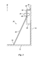
- two Support rods 60, 62 attached, which serve to hold the frame 50 in its operating position to hold on the facade or wall surface. This is in the Side view clearly in Figure 3.
- the frame 50 is supported by spacers 64, 66 against the surface 14 in such a way that the frame plane is parallel to the surface 14 and the plasma nozzle 10 in a suitable Distance to the surface 14 can be kept.
- the parallel support rods 60, 62 are attached by joints 68 to the frame 50 and opposite the Angled frame level and rest with their lower ends 70 on the floor 72 in the area in front of the surface 14, so that the support rods 60, 62, Include surface 14 and bottom 72 in a right triangle.
- suitable means may be a sliding of the support rods 60, 62 onto the floor 72 can be prevented so that the frame 50 in its leaning against the surface 14 Position is held.
- the support rods 60, 62 can also be telescopic be adjustable in length so that the height at which the frame 50 extends leaning against the surface 14 is adjustable.
- the holder comprises a carriage 80 which passes through Wheels 82, 84 rests on the floor 72 and can be moved along the facade or wall is.
- the plasma nozzle 10 is not moved in a frame here, but rather is only attached to a vertical guide rail 86, the one Up and down movement along the coordinate Y parallel to the vertical surface 14 allows.
- a strip-wise scan As described above Corresponds to the scanning process.
- this arrangement can prove necessary, each time the carriage 80 moves, the distance the mouth 16 of the plasma nozzle 10 from the surface 14 and if necessary to correct for tolerances in the distance to compensate between the guide rail 86 and the surface 14.
Landscapes
- Physics & Mathematics (AREA)
- Optics & Photonics (AREA)
- Engineering & Computer Science (AREA)
- Mechanical Engineering (AREA)
- Plasma Technology (AREA)
Abstract
Description
- Figur 1
- zeigt einen Querschnitt durch eine Vorrichtung zur Durchführung des erfindungsgemäßen Verfahrens;
- Figur 2
- zeigt eine schematische Darstellung einer Halterung der erfindungsgemäßen Vorrichtung;
- Figur 3
- ist eine Seitenansicht der Anordnung aus Figur 2; und
- Figur 4
- zeigt eine weitere Ausführungsform der erfindungsgemäßen Vorrichtung aus einer Perspektive entsprechend Figur 3.
Claims (14)
- Verfahren zum Entfernen einer Lackschicht (12) auf Polymerbasis von der Oberfläche (14) einer Fassade oder einer Wand, dadurch gekennzeichnet, daß die Lackschicht (12) durch einen auf die Oberfläche (14) gerichteten Strahl (18) eines atmosphärischen Plasmas verascht wird.
- Verfahren gemäß Anspruch 1, dadurch gekennzeichnet, daß der Plasmastrahl (18) durch eine Hochfrequenzentladung in einer verdrallten Strömung eines Arbeitsgases erzeugt wird.
- Verfahren gemäß Anspruch 1 oder 2, dadurch gekennzeichnet, daß in den Plasmastrahl (18) ein die Veraschung förderndes Additiv eingespeist wird.
- Verfahren gemäß einem der vorhergehenden Ansprüche, dadurch gekennzeichnet, daß zumindest eine Plasmadüse (10) zur Erzeugung eines Plasmastrahls (18) streifenweise über die Oberfläche (14) hinweg bewegt wird.
- Verfahren gemäß Anspruch 4, dadurch gekennzeichnet, daß die Plasmadüse (10) jeweils nach dem Abtasten eines Streifens quer zur Abtastrichtung maximal um eine Streifenbreite versetzt wird und die Abtastrichtung umgekehrt wird.
- Verfahren gemäß Anspruch 4 oder 5, dadurch gekennzeichnet, daß der Abstand der Plasmadüse (10) von der Oberfläche (14) durch einen Abstandssensor (46) gemessen und geregelt wird.
- Verfahren gemäß Anspruch 4, 5 oder 6, dadurch gekennzeichnet, daß die Färbung des Plasmastrahls (18) in dem Bereich, in welchem die Veraschungsreaktion stattfindet, durch einen Farbsensor (48) analysiert wird und daß die Bewegung der Plasmadüse (10), die Intensität des Plasmastrahls (18) und/oder der Abstand der Plasmadüse (10) von der Oberfläche in Abhängigkeit von der Verfärbung geregelt werden.
- Vorrichtung zur Durchführung des Verfahrens gemäß einem der vorstehenden Ansprüche, gekennzeichnet durch mindestens eine Plasmadüse (10) zur Erzeugung eines Strahls (18) eines atmosphärischen Plasmas, sowie durch einen Halter (20), in welchem die Plasmadüse (10) in einer Position gehalten wird, in der ihre Mündung (16) auf die Oberfläche (14) gerichtet ist, welcher Halter (20) zumindest eine Antriebseinrichtung (53, 55) umfaßt, durch welche die Plasmadüse (10) über die Oberfläche (14) hinweg bewegt werden kann.
- Vorrichtung gemäß Anspruch 8, gekennzeichnet durch einen Abstandssensor zur Messung des Abstandes der Plasmadüse (10) von der Oberfläche (14).
- Vorrichtung gemäß einem der Ansprüche 8 oder 9, gekennzeichnet durch einen Farbsensor zur Analyse der Färbung des Plasmastrahls (18) in dem Bereich, in welchem die Veraschungsreaktion stattfindet.
- Vorrichtung gemäß einem der Ansprüche 8 bis 10, dadurch gekennzeichnet, daß der Halter (20) einen auf der Oberfläche (14) aufliegenden Rahmen (50) umfaßt, und daß die Antriebseinrichtung(en) (53, 55) zur zweidimensionalen Bewegung der Plasmadüse (10) innerhalb des Rahmens (50) in einer Ebene parallel zur Oberfläche (14) vorgesehen ist bzw. sind.
- Vorrichtung gemäß Anspruch 11, dadurch gekennzeichnet, daß der Rahmen (50) an der Fassade oder Wand aufhängbar ist.
- Vorrichtung gemäß Anspruch 11 oder 12, dadurch gekennzeichnet, daß an dem Rahmen (50) Stützen (60, 62) angebracht sind, die gegenüber der Ebene des Rahmens (50) abgewinkelt sind und auf dem Boden (72) ruhen und durch welche der Rahmen (50) in einer gegen die Fassade oder Wand angelehnten Position gehalten wird.
- Vorrichtung gemäß Anspruch 11, dadurch gekennzeichnet, daß der Halter (20) einen Wagen (80) umfaßt, der auf einer Bodenfläche (72) entlang der Fassade oder Wand verfahrbar ist, welcher Wagen (80) mit einer Führungseinrichtung (86) zur senkrechten Bewegung der Plasmadüse (10) vorgesehen ist.
Priority Applications (3)
| Application Number | Priority Date | Filing Date | Title |
|---|---|---|---|
| EP20020023330 EP1410852B1 (de) | 2002-10-18 | 2002-10-18 | Verfahren und Vorrichtung zum Entfernen einer Lackschicht auf Polymerbasis |
| ES02023330T ES2262742T3 (es) | 2002-10-18 | 2002-10-18 | Procedimiento y dispositivo para retirar una cpa de barniz con base de polimeros. |
| DE50206486T DE50206486D1 (de) | 2002-10-18 | 2002-10-18 | Verfahren und Vorrichtung zum Entfernen einer Lackschicht auf Polymerbasis |
Applications Claiming Priority (1)
| Application Number | Priority Date | Filing Date | Title |
|---|---|---|---|
| EP20020023330 EP1410852B1 (de) | 2002-10-18 | 2002-10-18 | Verfahren und Vorrichtung zum Entfernen einer Lackschicht auf Polymerbasis |
Publications (2)
| Publication Number | Publication Date |
|---|---|
| EP1410852A1 true EP1410852A1 (de) | 2004-04-21 |
| EP1410852B1 EP1410852B1 (de) | 2006-04-19 |
Family
ID=32039147
Family Applications (1)
| Application Number | Title | Priority Date | Filing Date |
|---|---|---|---|
| EP20020023330 Expired - Lifetime EP1410852B1 (de) | 2002-10-18 | 2002-10-18 | Verfahren und Vorrichtung zum Entfernen einer Lackschicht auf Polymerbasis |
Country Status (3)
| Country | Link |
|---|---|
| EP (1) | EP1410852B1 (de) |
| DE (1) | DE50206486D1 (de) |
| ES (1) | ES2262742T3 (de) |
Cited By (7)
| Publication number | Priority date | Publication date | Assignee | Title |
|---|---|---|---|---|
| WO2006007437A1 (en) * | 2004-06-16 | 2006-01-19 | Ppg Industries Ohio, Inc. | Methods for removal of polymeric coating layers from coated substrates |
| WO2006136467A1 (de) | 2005-04-22 | 2006-12-28 | Plasmatreat Gmbh | Verfahren und vorrichtung zur charakterisierung einer oberfläche eines werkstückes |
| KR100863830B1 (ko) * | 2004-06-16 | 2008-10-15 | 피피지 인더스트리즈 오하이오 인코포레이티드 | 코팅된 기재로부터 중합체 코팅층을 제거하는 방법 |
| DE102007037406A1 (de) * | 2007-08-08 | 2009-06-04 | Neoplas Gmbh | Verfahren und Vorrichtung zur plasmagestützten Oberflächenbehandlung |
| WO2010091361A2 (en) | 2009-02-08 | 2010-08-12 | Ap Solutions, Inc. | Plasma source and method for removing materials from substrates utilizing pressure waves |
| EP1639619B1 (de) * | 2003-06-16 | 2011-12-07 | Saint-Gobain Glass France | Verfahren und vorrichtung zum bereichsweisen entschichten von glasplatten |
| AU2015258178B2 (en) * | 2009-02-08 | 2016-12-01 | Ap Solutions, Inc. | Plasma source and method for removing materials from substrates utilizing pressure waves |
Citations (3)
| Publication number | Priority date | Publication date | Assignee | Title |
|---|---|---|---|---|
| US5789755A (en) * | 1996-08-28 | 1998-08-04 | New Star Lasers, Inc. | Method and apparatus for removal of material utilizing near-blackbody radiator means |
| WO2001043512A1 (de) * | 1999-12-09 | 2001-06-14 | Agrodyn Hochspannungstechnik Gmbh | Plasmadüse |
| EP1170066A1 (de) * | 2000-07-05 | 2002-01-09 | Förnsel, Peter | Verfahren und Vorrichtung zum Reinigen von Walzen oder Bänder |
-
2002
- 2002-10-18 EP EP20020023330 patent/EP1410852B1/de not_active Expired - Lifetime
- 2002-10-18 DE DE50206486T patent/DE50206486D1/de not_active Expired - Lifetime
- 2002-10-18 ES ES02023330T patent/ES2262742T3/es not_active Expired - Lifetime
Patent Citations (3)
| Publication number | Priority date | Publication date | Assignee | Title |
|---|---|---|---|---|
| US5789755A (en) * | 1996-08-28 | 1998-08-04 | New Star Lasers, Inc. | Method and apparatus for removal of material utilizing near-blackbody radiator means |
| WO2001043512A1 (de) * | 1999-12-09 | 2001-06-14 | Agrodyn Hochspannungstechnik Gmbh | Plasmadüse |
| EP1170066A1 (de) * | 2000-07-05 | 2002-01-09 | Förnsel, Peter | Verfahren und Vorrichtung zum Reinigen von Walzen oder Bänder |
Cited By (10)
| Publication number | Priority date | Publication date | Assignee | Title |
|---|---|---|---|---|
| EP1639619B1 (de) * | 2003-06-16 | 2011-12-07 | Saint-Gobain Glass France | Verfahren und vorrichtung zum bereichsweisen entschichten von glasplatten |
| WO2006007437A1 (en) * | 2004-06-16 | 2006-01-19 | Ppg Industries Ohio, Inc. | Methods for removal of polymeric coating layers from coated substrates |
| KR100863830B1 (ko) * | 2004-06-16 | 2008-10-15 | 피피지 인더스트리즈 오하이오 인코포레이티드 | 코팅된 기재로부터 중합체 코팅층을 제거하는 방법 |
| US8133324B2 (en) | 2004-06-16 | 2012-03-13 | Ppg Industries Ohio, Inc | Methods for removal of polymeric coating layers from coated substrates |
| WO2006136467A1 (de) | 2005-04-22 | 2006-12-28 | Plasmatreat Gmbh | Verfahren und vorrichtung zur charakterisierung einer oberfläche eines werkstückes |
| EP1875212A1 (de) * | 2005-04-22 | 2008-01-09 | PlasmaTreat GmbH | Verfahren und vorrichtung zur charakterisierung einer oberfläche eines werkstückes |
| DE102007037406A1 (de) * | 2007-08-08 | 2009-06-04 | Neoplas Gmbh | Verfahren und Vorrichtung zur plasmagestützten Oberflächenbehandlung |
| WO2010091361A2 (en) | 2009-02-08 | 2010-08-12 | Ap Solutions, Inc. | Plasma source and method for removing materials from substrates utilizing pressure waves |
| EP2396456A4 (de) * | 2009-02-08 | 2014-11-19 | Ap Solutions Inc | Plasmaquelle und verfahren zur materialentfernung von substraten mittels druckwellen |
| AU2015258178B2 (en) * | 2009-02-08 | 2016-12-01 | Ap Solutions, Inc. | Plasma source and method for removing materials from substrates utilizing pressure waves |
Also Published As
| Publication number | Publication date |
|---|---|
| EP1410852B1 (de) | 2006-04-19 |
| ES2262742T3 (es) | 2006-12-01 |
| DE50206486D1 (de) | 2006-05-24 |
Similar Documents
| Publication | Publication Date | Title |
|---|---|---|
| EP0582191B1 (de) | Vorrichtung und Verfahren für die Behandlung von empfindlichen Oberflächen, insbesondere von Skulpturen | |
| DE102006014694B3 (de) | Prozesskammer und Verfahren für die Bearbeitung eines Werkstoffs mit einem gerichteten Strahl elektromagnetischer Strahlung, insbesondere für eine Lasersintervorrichtung | |
| DE19822672B4 (de) | Verfahren und Vorrichtung zur Erzeugung eines gerichteten Gasstrahls | |
| EP1214154A2 (de) | Verfahren und vorrichtung zum herstellen einer abziehbaren schutzschicht für oberflächen, insbesondere für lackierte oberflächen von kraftfahrzeugkarosserien | |
| DE19822185A1 (de) | Vorrichtung und Verfahren zum Reinigen eines Transportbandes | |
| DE69410900T2 (de) | Verfahren und Vorrichtung zur Überwachung von Oberflächen-Laserreinigung | |
| EP1410852B1 (de) | Verfahren und Vorrichtung zum Entfernen einer Lackschicht auf Polymerbasis | |
| WO2017178580A1 (de) | Vorrichtung zur bearbeitung einer oberfläche eines werkstücks mit einem laserstrahl und verfahren zum betrieb der vorrichtung | |
| EP3669621B1 (de) | Plasmageneratormodul und dessen verwendung | |
| EP2244846B1 (de) | Verfahren und vorrichtung zum zumindest teilweisen entfernen einer beschichtung sowie oberflächenbehandlungsanlage | |
| DE102016106960A1 (de) | Vorrichtung zur Bearbeitung einer Oberfläche eines Werkstücks mit einem Laserstrahl und Verfahren zum Betrieb der Vorrichtung | |
| DE102005018926B4 (de) | Verfahren und Plasmadüse zum Erzeugen eines mittels hochfrequenter Hochspannung erzeugten atmosphärischen Plasmastrahls umfassend eine Vorrichtung jeweils zur Charakterisierung einer Oberfläche eines Werkstückes | |
| EP1971448A1 (de) | Verfahren und vorrichtung zur behandlung einer oberfläche, insbesondere um diese von verunreinigungen zu befreien | |
| DE3108248A1 (de) | Verfahren zur verbesserung der wirkung des chemikalieneinsatzes bei der geblaesetrocknung von fahrzeugen | |
| DE19746028C2 (de) | Verfahren zur elektrostatischen Oberflächenentladung und Entstaubung von Werkstücken und Vorrichtung zur Durchführung des Verfahrens | |
| EP4360840B1 (de) | Verfahren zum erzeugen eines reliefartigen dekors auf einer oberfläche eines keramischen druckmediums | |
| EP0486711B1 (de) | Vorrichtung zum Abblasen einer Flüssigkeit von einem Gegenstand | |
| DE19934399A1 (de) | Vorrichtung zur Reinigung der Oberfläche von rotationssymmetrischen Körpern, insbesondere von Druckzylindern für das Tiefdruckverfahren | |
| EP0745430A2 (de) | Reinigungsverfahren und Reinigungsvorrichtung für Beschichtungspulver | |
| EP2006409B1 (de) | Verfahren und Vorrichtung zum Ermitteln des Anteils zumindest eines Zuschlagstoffes eines Multikomponentenpulvers zum thermischen Spritzen | |
| DE4219712A1 (de) | Elektroerosions-Schneidevorrichtung und Elektroerosions-Schneideverfahren | |
| EP1587641A1 (de) | Verfahren und vorrichtung zur behandlung von oberfl chen mit fl ssigkeitsstrahlen | |
| DE10016534C2 (de) | Verfahren und Vorrichtung zum Staubschutz in einer Laserbearbeitungsvorrichtung | |
| DE102009025029B4 (de) | Verfahren und Reinigungsgerät zur Reinigung eines Kontaktelements für Halbleiterbausteine | |
| DE3223122C2 (de) |
Legal Events
| Date | Code | Title | Description |
|---|---|---|---|
| PUAI | Public reference made under article 153(3) epc to a published international application that has entered the european phase |
Free format text: ORIGINAL CODE: 0009012 |
|
| AK | Designated contracting states |
Kind code of ref document: A1 Designated state(s): AT BE BG CH CY CZ DE DK EE ES FI FR GB GR IE IT LI LU MC NL PT SE SK TR |
|
| AX | Request for extension of the european patent |
Extension state: AL LT LV MK RO SI |
|
| 17P | Request for examination filed |
Effective date: 20040730 |
|
| AKX | Designation fees paid |
Designated state(s): DE ES FR GB IE IT |
|
| 17Q | First examination report despatched |
Effective date: 20041227 |
|
| GRAP | Despatch of communication of intention to grant a patent |
Free format text: ORIGINAL CODE: EPIDOSNIGR1 |
|
| GRAS | Grant fee paid |
Free format text: ORIGINAL CODE: EPIDOSNIGR3 |
|
| GRAA | (expected) grant |
Free format text: ORIGINAL CODE: 0009210 |
|
| AK | Designated contracting states |
Kind code of ref document: B1 Designated state(s): DE ES FR GB IE IT |
|
| PG25 | Lapsed in a contracting state [announced via postgrant information from national office to epo] |
Ref country code: IT Free format text: LAPSE BECAUSE OF FAILURE TO SUBMIT A TRANSLATION OF THE DESCRIPTION OR TO PAY THE FEE WITHIN THE PRESCRIBED TIME-LIMIT;WARNING: LAPSES OF ITALIAN PATENTS WITH EFFECTIVE DATE BEFORE 2007 MAY HAVE OCCURRED AT ANY TIME BEFORE 2007. THE CORRECT EFFECTIVE DATE MAY BE DIFFERENT FROM THE ONE RECORDED. Effective date: 20060419 |
|
| REG | Reference to a national code |
Ref country code: GB Ref legal event code: FG4D Free format text: NOT ENGLISH |
|
| REF | Corresponds to: |
Ref document number: 50206486 Country of ref document: DE Date of ref document: 20060524 Kind code of ref document: P |
|
| REG | Reference to a national code |
Ref country code: IE Ref legal event code: FG4D Free format text: LANGUAGE OF EP DOCUMENT: GERMAN |
|
| GBT | Gb: translation of ep patent filed (gb section 77(6)(a)/1977) |
Effective date: 20060710 |
|
| REG | Reference to a national code |
Ref country code: ES Ref legal event code: FG2A Ref document number: 2262742 Country of ref document: ES Kind code of ref document: T3 |
|
| ET | Fr: translation filed | ||
| PLBE | No opposition filed within time limit |
Free format text: ORIGINAL CODE: 0009261 |
|
| STAA | Information on the status of an ep patent application or granted ep patent |
Free format text: STATUS: NO OPPOSITION FILED WITHIN TIME LIMIT |
|
| 26N | No opposition filed |
Effective date: 20070122 |
|
| PGFP | Annual fee paid to national office [announced via postgrant information from national office to epo] |
Ref country code: ES Payment date: 20141017 Year of fee payment: 13 Ref country code: IE Payment date: 20141015 Year of fee payment: 13 Ref country code: FR Payment date: 20141016 Year of fee payment: 13 Ref country code: GB Payment date: 20141016 Year of fee payment: 13 |
|
| PGFP | Annual fee paid to national office [announced via postgrant information from national office to epo] |
Ref country code: IT Payment date: 20141017 Year of fee payment: 13 |
|
| GBPC | Gb: european patent ceased through non-payment of renewal fee |
Effective date: 20151018 |
|
| REG | Reference to a national code |
Ref country code: IE Ref legal event code: MM4A |
|
| PG25 | Lapsed in a contracting state [announced via postgrant information from national office to epo] |
Ref country code: GB Free format text: LAPSE BECAUSE OF NON-PAYMENT OF DUE FEES Effective date: 20151018 Ref country code: IT Free format text: LAPSE BECAUSE OF NON-PAYMENT OF DUE FEES Effective date: 20151018 |
|
| REG | Reference to a national code |
Ref country code: FR Ref legal event code: ST Effective date: 20160630 |
|
| PG25 | Lapsed in a contracting state [announced via postgrant information from national office to epo] |
Ref country code: FR Free format text: LAPSE BECAUSE OF NON-PAYMENT OF DUE FEES Effective date: 20151102 |
|
| PG25 | Lapsed in a contracting state [announced via postgrant information from national office to epo] |
Ref country code: IE Free format text: LAPSE BECAUSE OF NON-PAYMENT OF DUE FEES Effective date: 20151018 |
|
| REG | Reference to a national code |
Ref country code: ES Ref legal event code: FD2A Effective date: 20170203 |
|
| PG25 | Lapsed in a contracting state [announced via postgrant information from national office to epo] |
Ref country code: ES Free format text: LAPSE BECAUSE OF NON-PAYMENT OF DUE FEES Effective date: 20151019 |
|
| PGFP | Annual fee paid to national office [announced via postgrant information from national office to epo] |
Ref country code: DE Payment date: 20181022 Year of fee payment: 17 |
|
| REG | Reference to a national code |
Ref country code: DE Ref legal event code: R119 Ref document number: 50206486 Country of ref document: DE |
|
| PG25 | Lapsed in a contracting state [announced via postgrant information from national office to epo] |
Ref country code: DE Free format text: LAPSE BECAUSE OF NON-PAYMENT OF DUE FEES Effective date: 20200501 |