EP1410852A1 - Method and apparatus for the removal of a polymer-based layer of paint - Google Patents
Method and apparatus for the removal of a polymer-based layer of paint Download PDFInfo
- Publication number
- EP1410852A1 EP1410852A1 EP02023330A EP02023330A EP1410852A1 EP 1410852 A1 EP1410852 A1 EP 1410852A1 EP 02023330 A EP02023330 A EP 02023330A EP 02023330 A EP02023330 A EP 02023330A EP 1410852 A1 EP1410852 A1 EP 1410852A1
- Authority
- EP
- European Patent Office
- Prior art keywords
- plasma
- plasma nozzle
- nozzle
- jet
- frame
- Prior art date
- Legal status (The legal status is an assumption and is not a legal conclusion. Google has not performed a legal analysis and makes no representation as to the accuracy of the status listed.)
- Granted
Links
Images


Classifications
-
- B—PERFORMING OPERATIONS; TRANSPORTING
- B44—DECORATIVE ARTS
- B44D—PAINTING OR ARTISTIC DRAWING, NOT OTHERWISE PROVIDED FOR; PRESERVING PAINTINGS; SURFACE TREATMENT TO OBTAIN SPECIAL ARTISTIC SURFACE EFFECTS OR FINISHES
- B44D3/00—Accessories or implements for use in connection with painting or artistic drawing, not otherwise provided for; Methods or devices for colour determination, selection, or synthesis, e.g. use of colour tables
- B44D3/16—Implements or apparatus for removing dry paint from surfaces, e.g. by scraping, by burning
- B44D3/166—Implements or apparatus for removing dry paint from surfaces, e.g. by scraping, by burning by heating, e.g. by burning
-
- B—PERFORMING OPERATIONS; TRANSPORTING
- B08—CLEANING
- B08B—CLEANING IN GENERAL; PREVENTION OF FOULING IN GENERAL
- B08B7/00—Cleaning by methods not provided for in a single other subclass or a single group in this subclass
- B08B7/0035—Cleaning by methods not provided for in a single other subclass or a single group in this subclass by radiant energy, e.g. UV, laser, light beam or the like
-
- G—PHYSICS
- G01—MEASURING; TESTING
- G01N—INVESTIGATING OR ANALYSING MATERIALS BY DETERMINING THEIR CHEMICAL OR PHYSICAL PROPERTIES
- G01N21/00—Investigating or analysing materials by the use of optical means, i.e. using sub-millimetre waves, infrared, visible or ultraviolet light
- G01N21/62—Systems in which the material investigated is excited whereby it emits light or causes a change in wavelength of the incident light
- G01N21/71—Systems in which the material investigated is excited whereby it emits light or causes a change in wavelength of the incident light thermally excited
Landscapes
- Physics & Mathematics (AREA)
- Optics & Photonics (AREA)
- Engineering & Computer Science (AREA)
- Mechanical Engineering (AREA)
- Plasma Technology (AREA)
Abstract
Description
Die vorliegende Erfindung betrifft ein Verfahren zum Entfernen einer Lackschicht auf Polymerbasis von der Oberfläche einer Fassade oder einer Wand, sowie eine Vorrichtung zur Durchführung dieses Verfahrens.The present invention relates to a method for removing a lacquer layer polymer-based from the surface of a facade or wall, as well an apparatus for performing this method.
Das Entfernen eines Lackauftrags auf Polymerbasis von einer Oberfläche erweist sich häufig als problematisch, da der Lack gewöhnlich hartnäckig auf dem Untergrund haftet. Insbesondere stellt sich dieses Problem beim Entfernen von Farbaufträgen, z.B. von Graffiti, von Fassaden und Wandflächen von Häusern, Gebäuden und dergleichen. Durch mechanische Reinigungsmittel in Verbindung mit Wasser und Detergenzien ist die Farbe nur äußerst mühsam oder gar nicht zu entfernen. Selbst wenn ein begrenzter Reinigungserfolg eintritt, verbleiben häufig sichtbare Spuren auf der Fassade. Erfolgversprechender ist der Einsatz lösungsmittelhaltiger Substanzen, doch deren Verwendung ist unter dem Gesichtspunkt des Umweltschutzes problematisch und birgt zudem die Gefahr, daß die Fassadenoberfläche angegriffen und beeinträchtigt wird. Schließlich ist der Reinigungsvorgang auch in diesem Fall sehr zeitaufwendig und führt nicht immer zu einer vollständigen und spurlosen Entfernung der Lackschicht.Removing a polymer-based paint application from a surface proves often proves to be problematic because the varnish is usually stubborn on the surface liable. In particular, this problem arises when removing Paint applications, e.g. of graffiti, of facades and wall surfaces of houses, Buildings and the like. Connected by mechanical cleaning agents with water and detergents, the color is extremely difficult or not at all to remove. Even if the cleaning success is limited, remain often visible traces on the facade. The application is more promising solvent-containing substances, but their use is from the point of view of environmental protection is problematic and also carries the risk of that the facade surface is attacked and impaired. Finally is in this case, the cleaning process is also very time-consuming and does not result always complete and trace-free removal of the paint layer.
Aufgabe der vorliegenden Erfindung ist es daher, ein Verfahren zum Entfernen einer Lackschicht auf Polymerbasis von einer Fassaden- oder Wandoberfläche zu schaffen, welches effizienter ist als die bekannten Verfahren und somit die Lackschicht zuverlässiger entfernt, gleichzeitig jedoch die Oberfläche selbst schonender behandelt und mit geringerem Arbeitsaufwand durchzuführen ist.The object of the present invention is therefore a method for removal a polymer-based paint layer from a facade or wall surface to create which is more efficient than the known methods and thus the Lacquer layer removed more reliably, but at the same time the surface itself handled more gently and with less work.
Diese Aufgabe wird erfindungsgemäß dadurch gelöst, daß die Lackschicht durch einen auf die Oberfläche gerichteten Strahl eines atmosphärischen Plasmas verascht wird.This object is achieved in that the paint layer through a beam of atmospheric plasma directed at the surface is ashes.
Ein solcher atmosphärischer Plasmastrahl läßt sich durch eine Plasmadüse erzeugen, wie sie beispielsweise aus der DE 195 32 412 C2 sowie aus einer Reihe weiterer Konstruktionen bekannt ist. Solche Plasmadüsen erzeugen einen Strahl eines relativ kühlen atmosphärischen Plasmas, welches eine relativ niedrige Temperatur aufweist und eine hohe Konzentration an chemisch hochreaktiven Ionen, radikalen und angeregten Atomen und Molekülen enthält. Es neigt daher stark dazu, mit der behandelten Oberflächenschicht eine chemische Reaktion einzugehen, durch welche diese zerstört werden kann. Die Anwendbarkeit des erfindungsgemäßen Verfahrens beruht darauf, daß ein Polymer durch das Plasma vollständig verascht werden kann, d. h., das Polymermaterial wird durch die chemische Reaktion zersetzt. Besteht die zu behandelnde Oberfläche selbst aus einem anorganischen Material, so wird sie durch den Plasmastrahl nicht angegriffen, so daß lediglich die Polymer-Schicht verascht wird und restlos entfernt werden kann, während die Gefahr von Beschädigungen, Verfärbungen oder dergleichen ausgeschlossen ist. Insbesondere eignet sich das erfindungsgemäße Verfahren daher zum Reinigen von Fassaden und Hauswänden von Lackschichten auf Polymerbasis.Such an atmospheric plasma jet can be generated by a plasma nozzle, as for example from DE 195 32 412 C2 and from a series other constructions is known. Such plasma nozzles generate a jet a relatively cool atmospheric plasma which is relatively low Has temperature and a high concentration of chemically highly reactive Contains ions, radical and excited atoms and molecules. It therefore tends strongly to a chemical reaction with the treated surface layer through which it can be destroyed. The applicability of the The inventive method is based on the fact that a polymer through the plasma can be completely incinerated, d. that is, the polymer material is replaced by the chemical reaction decomposes. Is the surface to be treated itself an inorganic material, so it is not attacked by the plasma beam, so that only the polymer layer is incinerated and completely removed can be, while the risk of damage, discoloration or the like is excluded. The invention is particularly suitable Process for cleaning facades and house walls from layers of paint based on polymer.
Gegenüber dem bekannten Reinigungsverfahren ist das erfindungsgemäße Verfahren erheblich effizienter und gewährleistet eine schonende Behandlung der zu reinigenden Oberflächen, da auf die Verwendung aggressiver chemischer Lösungsmittel und mechanischer Reinigungsvorrichtungen vollständig verzichtet werden kann. Der Lackauftrag läßt sich somit schonend und spurlos von der Fassade entfernen.The method according to the invention is compared to the known cleaning method considerably more efficient and ensures gentle treatment of the surfaces to be cleaned because of the use of aggressive chemical solvents and mechanical cleaning devices completely dispensed with can be. The varnish can thus be applied gently and without a trace by the Remove the facade.
Vorzugsweise wird der Plasmastrahl durch eine Hochfrequenzentladung in einer verdrallten Strömung eines Arbeitsgases erzeugt. Bei diesem handelt es sich beispielsweise um Luft oder Argon. Versuche haben gezeigt, daß der Veraschungsprozeß bei der Verwendung von Argon besonders effizient abläuft, so daß eine besonders gründliche Reinigung durchgeführt werden kann.The plasma beam is preferably emitted by a high-frequency discharge swirled flow of a working gas generated. This is, for example for air or argon. Experiments have shown that the ashing process runs particularly efficiently when using argon, so that a particularly thorough cleaning can be performed.
In einer bevorzugten Ausführungsform des Verfahrens wird ein Additiv in den Plasmastrahl eingespeist, welches dazu dient, die Veraschungsreaktion zu unterstützen. Es ist beispielsweise aus der WO 01/32949 A1 bekannt, durch das Einspeisen eines Precursor-Materials eine Abscheidungsreaktion herbeizuführen und eine Oberfläche zu beschichten. Im vorliegenden Fall findet eine chemische Reaktion des Additivs mit der Polymerschicht statt, die das Ablösen der Schicht und somit die Veraschungsreaktion fördert. Bei dem Additiv kann es sich um eine vernebelte Flüssigkeit handeln. In a preferred embodiment of the method, an additive is added to the Plasma jet fed, which serves to support the ashing reaction. It is known for example from WO 01/32949 A1, through which Feeding a precursor material to cause a deposition reaction and to coat a surface. In the present case there is a chemical Reaction of the additive with the polymer layer instead of the peeling of the layer and thus promotes the ashing reaction. The additive can be act a nebulized liquid.
In einer bevorzugten Ausführungsform des Verfahrens wird zumindest eine Plasmadüse zur Erzeugung eines Plasmastrahls streifenweise über die Oberfläche hinwegbewegt. Diese Bewegung kann vorzugsweise auf solche Weise ausgeführt werden, daß die Düse jeweils nach dem Abtasten eines Streifens quer zur Abtastrichtung maximal um eine Streifenbreite versetzt wird und die Abtastrichtung anschließend umgekehrt wird. Es handelt sich somit um eine Hin- und Herbewegung, bei welcher bei jeder Richtungsumkehr ein Versatz der Düse um höchstens eine Streifenbreite durchgeführt wird. Durch diese Bewegung läßt sich ein Oberflächenareal effizient streifenweise von der Lackschicht befreien.In a preferred embodiment of the method, at least one plasma nozzle is used to generate a plasma jet in strips across the surface moved away. This movement can preferably be carried out in such a way that the nozzle is traversed to the scanning direction after each scanning of a strip is offset by a maximum of one stripe width and the scanning direction then reversed. So it's a back and forth movement, in which each time the direction is reversed, the nozzle is offset by at most a stripe width is performed. This movement allows one to Efficiently remove the paint layer from the surface area in strips.
Vorzugsweise wird der Abstand der Düse von der Oberfläche durch einen Abstandssensor gemessen, dessen Signal zur Abstandsregelung verwendet werden kann. Weiter vorzugsweise läßt sich die Färbung des Plasmastrahls im Reaktionsbereich durch einen Farbsensor analysieren, und die Bewegung der Düse, die Intensität des Plasmastrahls und/oder der Abstand der Düse von der Oberfläche werden in Abhängigkeit von der Verfärbung geregelt. Hierbei wird der Umstand ausgenutzt, daß sich die Farbe der Plasmaflamme während des Veraschungsvorgangs ändert. Es läßt sich somit feststellen, ob in der Flamme augenblicklich eine chemische Reaktion stattfindet, die zu dem Veraschen führt. Die Beobachtung dieses Farbumschlags kann somit zur Steuerung des Verfahrens genutzt werden.The distance between the nozzle and the surface is preferably determined by a distance sensor measured, whose signal are used for distance control can. The coloring of the plasma jet in the reaction area can also be preferred analyze through a color sensor, and the movement of the nozzle, the intensity of the plasma jet and / or the distance of the nozzle from the surface are regulated depending on the discoloration. This is the circumstance exploited that the color of the plasma flame during the ashing process changes. It can thus be determined whether the flame is instantaneous a chemical reaction takes place that leads to ashing. The observation of this color change can thus be used to control the process be used.
Eine Vorrichtung zur Durchführung des erfindungsgemäßen Verfahrens wird in den Unteransprüchen 8 bis 14 beschrieben.A device for carrying out the method according to the invention is described in the subclaims 8 to 14 described.
Im folgenden werden bevorzugte Ausführungsformen der Erfindung anhand der Zeichnung näher erläutert.
- Figur 1
- zeigt einen Querschnitt durch eine Vorrichtung zur Durchführung des erfindungsgemäßen Verfahrens;
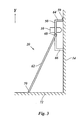
- Figur 2
- zeigt eine schematische Darstellung einer Halterung der erfindungsgemäßen Vorrichtung;
- Figur 3
- ist eine Seitenansicht der Anordnung aus Figur 2; und
- Figur 4
- zeigt eine weitere Ausführungsform der erfindungsgemäßen Vorrichtung aus einer Perspektive entsprechend Figur 3.
- Figure 1
- shows a cross section through an apparatus for performing the method according to the invention;
- Figure 2
- shows a schematic representation of a holder of the device according to the invention;
- Figure 3
- is a side view of the arrangement of Figure 2; and
- Figure 4
- shows a further embodiment of the device according to the invention from a perspective corresponding to FIG. 3.
Figur 1 zeigt eine Plasmadüse 10, die zum Entfernen einer Lackschicht 12 auf
Polymerbasis von der Oberfläche 14 einer Fassade oder einer Wand ausgebildet
ist. Bei der Wand kann es sich beispielsweise um eine Gebäudewand aus einem
mineralischen Material wie etwa Stein handeln. Die Oberfläche 14 kann jedoch
auch aus Metall oder einem anderen anorganischen Material bestehen. Die Plasmadüse
10 selbst ist bekannt und wird beispielsweise in der EP 1 170 066 A1
ausführlich beschrieben. Auf Einzelheiten des Aufbaus der Plasmadüse 10 und
auf deren Funktionsweise soll im folgenden noch näher eingegangen werden.FIG. 1 shows a
Die Mündung 16 der Plasmadüse 10 ist der mit der Lackschicht 12 versehenen
Oberfläche 14 zugewandt und von dieser beabstandet, so daß der aus der Mündung
16 austretende Plasmastrahl 18 auf die Oberfläche 14 gerichtet ist. Im
Plasmastrahl 18 herrscht eine relativ niedrige Temperatur von beispielsweise
500° bis 1500° C, und er enthält eine hohe Konzentration chemisch hochreaktiver
Ionen, Radikalen und angeregten Atomen und Molekülen. Die Lackschicht
12 kann somit durch den auftreffenden Plasmastrahl 18 verascht werden, d. h.,
es findet eine chemische Reaktion statt, die die Schicht zersetzt, so daß sie sich
von der Oberfläche 14 löst. Besteht diese, wie oben beschrieben, aus einem anorganischen
Material, so besteht keine Gefahr der Beeinträchtigung der Oberfläche
14 durch den Plasmastrahl 18.The
Soll ein größerer Oberflächenbereich von der Schicht 12 befreit werden, so empfiehlt
sich eine streifenweise Bearbeitung der Oberfläche 14. Die Plasmadüse 10
wird zu diesem Zweck in einem Halter 20 gehalten, durch welchen die Düse in
einer Ebene über die Oberfläche 14 hinweg bewegt werden kann. Dieser Halter
20, auf dessen Bestandteile im Zusammenhang mit den folgenden Figuren noch
näher eingegangen werden soll, umfaßt unter anderem einen Haltering 22, der
die Düse 10 von außen umschließt und welcher durch ein Gestänge mit zwei zueinander
senkrechten Führungsstangen 24, 54 geführt wird. Es ist möglich, den
Abstand der Plasmadüse 10 von der Oberfläche 14 durch einen am Haltering 22
angebrachten Antrieb zu verändern, der in Figur 2 dargestellt ist.If a larger surface area is to be freed from the
Wird die Plasmadüse 10 in Richtung des Pfeils X parallel zur Oberfläche 14 über
diese hinweg geführt, so überstreicht der Plasmastrahl 18 einen Längsstreifen
der Schicht 12, so daß diese verascht wird. Die in Figur 1 linke Hälfte eines solchen
Oberflächenstreifens 26, der durch den Plasmastrahl 18 abgetastet wurde,
ist somit bereits verascht worden und chemisch von der Oberfläche 14 gelöst.
Zum Entfernen des abgelösten Schichtmaterials 26 kann zusätzlich ein Hochdruckstrahl
wie etwa ein Luftdruckstrahl, ein Wasserstrahl oder ein Dampfstrahl
eingesetzt werden, der dem Plasmastrahl 18 auf seinem Weg nachfolgt.
Ferner können dem Hochdruckstrahl Abrasivstoffe wie etwa Sand oder dergleichen
beigemischt sein, die den Ablösungsprozeß unterstützen.The
Die Plasmadüse 10 selbst weist eine rohrförmige, zur Mündung 16 hin verjüngte
und elektrisch geerdete Außenelektrode 28 auf, an die sich am rückwärtigen
Ende ein rohrförmges Gehäuse 30 aus elektrisch isolierendem Material wie etwa
Keramik anschließt. Ein Deckel 32 des Gehäuses 30 bildet einen Einlaß 34,
über den mit Hilfe eines Schlauches ein Arbeitsgas in die Plasmadüse eingeleitet
werden kann. Bei diesem kann es sich beispielsweise um Luft, Argon oder ein
anderes geeignetes Arbeitsgas wie etwa Stickstoff handeln. Im Inneren des Gehäuses
30 ist eine Dralleinrichtung 36 angeordnet, die die Form einer den Querschnitt
des Gehäuses ausfüllenden Scheibe mit einem Kranz schräg in Umfangsrichtung
angestellter Kanäle 38 hat und in der Mitte eine koaxial in die Außenelektrode
28 ragende Stiftelektrode 40 trägt.The
Im Betrieb wird die Plasmadüse 10 von dem Arbeitsgas durchströmt, das durch
die Dralleinrichtung 36 verdrallt wird und somit wirbelförmig durch die verhältnismäßig
lange Außenelektrode 28 zur Mündung 16 strömt und dabei auf der
Mittelachse der Außenelektrode 28 einen Wirbelkern bildet. An die Stiftelektrode
40 wird mit Hilfe eines Hochfrequenz-Spannungsgenerators 42 eine Spannung
in der Größenordnung von 5 bis 30 kV angelegt, deren Frequenz beispielsweise
10 bis 20 kHz beträgt.In operation, the working gas flows through the
Die aus einem Keramikmaterial bestehende Wand des Gehäuses 30 bildet ein
Dielektrikum, so daß es durch die an die Stiftelektrode 40 und die aus leitendem
Material bestehende Dralleinrichtung 36 angelegte Spannung zunächst zu
einer Koronaentladung kommt, durch die dann eine Bogenentladung zwischen
der Stiftelektrode 40 und der Außenelektrode 28 gezündet wird. Der Lichtbogen
44 dieser Bogenentladung wird durch die verdrallte Strömung des Arbeitsgases
mitgerissen und so daran gehindert, unmittelbar auf die Wand der Außenelektrode
28 überzuschlagen. Statt dessen wird der Lichtbogen im Wirbelkern der
drallförmigen Strömung kanalisiert, so daß er sich erst in der Mündung 16 zur
Außenelektrode verzweigt. Da der Abstand zwischen der Spitze der Stiftelektrode
40 und der Mündung 16 der Plasmadüse 10 deutlich größer ist als der Durchmesser
der Mündung 16, wird eine verhältnismäßig lange Entladungsstrecke gebildet,
in der das mit hoher Geschwindigkeit im Wirbelkern rotierende Arbeitsgas
in innige Berührung mit dem Lichtbogen kommt. Auf diese Weise wird außerhalb
des thermischen Plasmas des Lichtbogens ein Sekundärplasma erzeugt,
das stark mit Ionen, angeregten Atomen und Molekülen und hochreaktiven Radikalen
angereichert ist. Dieses Sekundärplasma wird durch die Mündung 16
ausgeblasen und bildet den Plasmastrahl 18, der sich aufgrund der Verdrallung
gut an die Schicht 12 auf der Oberfläche 14 anschmiegt. Durch dieses Anschmiegen
wird der Plasmastrahl 18 beim Auftreffen auf die Schicht 12 verbreitert.
Diese Aufweitung des Plasmastrahls 18 bestimmt die Breite des von der
Plasmadüse 10 abgetasteten Streifens.The wall of the
Zur Messung und Regelung des Abstandes der Plasmadüse von der Oberfläche
dient ein Abstandssensor 46. Darüber hinaus läßt sich die Färbung des Plasmastrahls
in dem Bereich, in dem die Veraschungsreaktion stattfindet, durch einen
Farbsensor 48 analysieren. Die Farbe und insbesondere ein Farbumschlag der
Plasmaflamme gibt Aufschluß darüber, ob die Veraschung erfolgreich durchgeführt
wird. Die Bewegung der Plasmadüse 10, die Intensität des Plasmastrahls
18 und/oder der Abstand der Plasmadüse 10 von der Oberfläche 14 lassen sich
somit in Abhängigkeit von der Verfärbung der Plasmaflamme regeln. Beispielsweise
kann verhindert werden, daß die Plasmadüse 10 zu schnell über die Oberfläche
14 hinweggeführt wird und nicht veraschte Reste der Lackschicht 12 auf
der Oberfläche 14 verbleiben.For measuring and controlling the distance of the plasma nozzle from the surface
a
Abweichend von der hier dargestellten Ausführungsform der Plasmadüse 10
kommt es in Betracht, Plasmadüsen anderer Konstruktion zu verwenden, die für
den hier dargestellten Einsatz vorteilhaft sind. Beispielsweise kann die Mündung
16 der Düse als ein quer zur Mittelachse der Plasmadüse 10 verlaufender
schmaler Schlitz ausgebildet sein, so daß die Breite des abgetasteten Streifens
erhöht werden kann. Ferner ist es denkbar, die Plasmadüse 10 exzentrisch in einem
Rotationskopf anzuordnen, dessen Rotationsachse parallel zur Mittelachse
der Plasmadüse 10 verläuft, so daß die Düse 10 während der Translationsbewegung
in Pfeilrichtung X gleichzeitig um die Rotationsachse herumgeführt wird.
Die Breite des abgetasteten Streifens kann auch dadurch vergrößert werden,
daß die Mündung 16 der Plasmadüse 10 gegenüber deren Mittelachse abgewinkelt
ist und rotiert. Eine konische oder fächerförmige Aufweitung des Plasmastrahls
18 erweist sich zur Verbreiterung des abgetasteten Streifens ebenfalls als
hilfreich. Im Hinblick auf solche vorteilhaften Ausführungsformen wird insbesondere
auf die WO 01/43512 A1, die WO 99/52333 sowie die EP 1 067 829 A2
verwiesen.Deviating from the embodiment of the
Ferner läßt sich der Veraschungsprozeß unterstützen, indem ein Additiv in den
Plasmastrahl 18 eingespeist wird. Als geeignetes Additiv kommt beispielsweise
Hexamethylendisiloxan (HMDSO) in Betracht. Das Additiv kann in Form einer
vernebelten Flüssigkeit, also als Aerosol in den Strahl 18 injiziert werden, so daß
es beim Auftreffen auf die Lackschicht 12 chemisch mit dem Polymer reagiert.
Hierzu ist die Plasmadüse 10 abweichend von der in Figur 1 dargestellten Ausführungsform
mit einer geeigneten Zufuhreinrichtung zu versehen, wie beispielsweise
einer Lanze oder einem Röhrchen, das im Mündungsbereich der
Plasmadüse 10 in den Plasmastrahl 18 mündet. Entsprechende Ausführungsformen
sind in der WO 01/32949 A1 offenbart.Furthermore, the ashing process can be supported by adding an additive to the
Im folgenden soll näher auf einen Halter 20 eingegangen werden, der dazu geeignet
ist, eine ebene Oberfläche effizient zu bearbeiten und insbesondere an einer
Fassade oder Wand eines Gebäudes eingesetzt zu werden. Der in Figur 2 dargestellte
Halter 20 umfaßt zu diesem Zweck einen Rahmen 50, der in einer Ebene
parallel zu der Oberfläche 14 auf dieser aufliegt. Der Rahmen 50 ist rechteckig
und hält in seinem Inneren eine Führungsstange 24, die parallel zu seinen
Längsseiten verläuft. Die Führungsstange 24 ist in den kürzeren Seitenabschnitten
52 des Rahmes 50 durch eine Antriebseinrichtung 53 beweglich gehalten,
so daß sie in einer Richtung senkrecht zu ihrer Längsachse entlang der Seitenabschnitte
52 bewegt werden kann. Senkrecht zu dieser ersten Führungsstange
24 erstreckt sich eine zweite Führungsstange 54 parallel zu den kürzeren
Seitenabschnitten 52, welche durch eine weitere Antriebseinrichtung 55 entlang
des längeren Rahmenabschnitts 56 bewegt werden kann. An den Führungsstangen
24,54 ist der Haltering 22 jeweils durch Führungen 58 verschiebbar befestigt,
so daß er durch eine Bewegung der zweiten Führungsstange 54 entlang
der ersten Führungsstange 24 in der Richtung X bzw. durch eine Bewegung der
ersten Führungsstange 24 entlang der zweiten Führungsstange 52 in der dazu
senkrechten Richtung Y verschoben wird. Auf diese Weise kann die Plasmadüse
10 in dem Rahmen 50 in einer Ebene entlang der Koordinaten X, Y hin und her
bewegt werden, so daß sich der gesamte Flächenbereich von der Plasmadüse 10
abtasten läßt, der von dem Rahmen 50 umschlossen wird.The following is a closer look at a
Um diesen Flächenbereich möglichst effizient zu bearbeiten, kann die Bewegung
insbesondere so erfolgen, daß zunächst ein Streifen in Richtung X in der in Figur
1 beschriebenen Weise abgetastet wird, also in Figur 2 von links nach rechts
entlang der ersten Führungsstange 24, bis die Plasmadüse 10 an dem rechten
Rahmenabschnittt 52 anschlägt. Dann wird die Plasmadüse 10 um eine Streifenbreite
versetzt, indem die erste Führungsstange 24 entlang der zweiten Führungsstange
54 verfahren wird, und die Abtastrichtung wird umgekehrt, so daß
sich die Plasmadüse 10 von rechts nach links bewegt. Es handelt sich also um
eine hin- und hergehende Bewegung, wobei bei jedem Richtungswechsel ein
Versatz um maximal eine Streifenbreite stattfindet. Diese Bewegung kann beispielsweise
durch eine Steuereinrichtung mit einem Steuerprogramm gesteuert
werden.In order to process this area as efficiently as possible, the movement can
in particular take place in such a way that first a strip in the direction X in the figure
1 is scanned, that is to say in FIG. 2 from left to right
along the
Ferner umfaßt der Haltering 22 einen Antrieb 57, durch welchen sich die Plasmadüse
10 in einer Richtung senkrecht zur Rahmenebene bewegen läßt, so daß
der Abstand der Mündung 16 der Düse 10 von der Oberfläche 14 verstellbar
und unter Einbeziehung des Signals des Abstandssensors 46 und gegebenenfalls
des Farbsensors 48 aus Figur 1 regelbar ist.Furthermore, the retaining
An den oberen beiden Ecken des Rahmens 50 sind Ösen 59 angebracht, durch
welche der Rahmen 50 durch geeignete Mittel wie Haken oder dergleichen an
der Oberfläche 14 aufgehängt werden kann. Alternativ ist es möglich, den Rahmen
50 lediglich an die Oberfläche 14 anzulehnen. Zu diesem Zweck sind an
den gegenüberliegenden kürzeren Seitenabschnitten 52 des Rahmens 50 zwei
Stützstangen 60, 62 angebracht, die dazu dienen, den Rahmen 50 in seiner Betriebsposition
an der Fassaden- oder Wandoberfläche zu halten. Dies wird in der
Seitenansicht in Figur 3 deutlich. Der Rahmen 50 stützt sich durch Abstandshalter
64, 66 auf solche Weise gegen die Oberfläche 14 ab, daß die Rahmenebene
parallel zur Oberfläche 14 liegt und die Plasmadüse 10 in einem geeigneten
Abstand zur Oberfläche 14 gehalten werden kann. Die parallelen Stützstangen
60, 62 sind durch Gelenke 68 am Rahmen 50 angebracht und gegenüber der
Rahmenebene abgewinkelt und ruhen mit ihren unteren Enden 70 auf dem Boden
72 im Bereich vor der Oberfläche 14, so daß die Stützstangen 60, 62, die
Oberfläche 14 und der Boden 72 ein rechtwinkliges Dreieck einschließen. Durch
geeignete Mittel kann ein Abrutschen der Stützstangen 60, 62 auf den Boden 72
verhindert werden, so daß der Rahmen 50 in seiner gegen die Oberfläche 14 gelehnten
Position gehalten wird. Die Stützstangen 60, 62 können ferner teleskopartig
längenverstellbar sein, so daß die Höhe, in welcher der Rahmen 50 sich
an die Oberfläche 14 anlehnt, einstellbar ist.At the top two corners of the
Es ist selbstverständlich möglich, ein Gestell zum Halten des Rahmens an der
Wand auf andere Weise auszubilden, etwa mit vor der Wand angebrachten Gestellen
oder dergleichen. Eine besonders vorteilhafte Ausführungsform ist in Figur
4 dargestellt. In diesem Fall umfaßt der Halter einen Wagen 80, der durch
Räder 82, 84 auf dem Boden 72 ruht und entlang der Fassade oder Wand verfahrbar
ist. Die Plasmadüse 10 wird hier nicht in einem Rahmen bewegt, sondern
ist lediglich an einer senkrechten Führungsschiene 86 angebracht, die eine
Auf- und Abbewegung entlang der Koordinate Y parallel zur senkrechten Oberfläche
14 ermöglicht. Durch diese Bewegung in Verbindung mit einem schrittweisen
Verfahren des Wagens 80 kann ein Flächenbereich der Oberfläche 14
durch eine streifenweise Abtastung bearbeitet werden, die dem oben beschriebenen
Abtastvorgang entspricht. Insbesondere bei dieser Anordnung kann es sich
als erforderlich erweisen, bei jedem Verfahrvorgang des Wagens 80 den Abstand
der Mündung 16 der Plasmadüse 10 von der Oberfläche 14 zu messen und gegebenenfalls
zu korrigieren, um beim Verfahren auftretende Toleranzen im Abstand
zwischen der Führungsschiene 86 und der Oberfläche 14 auszugleichen.It is of course possible to use a frame to hold the frame
Form the wall in a different way, for example with frames attached in front of the wall
or similar. A particularly advantageous embodiment is shown in FIG
4 shown. In this case, the holder comprises a
Claims (14)
Priority Applications (3)
| Application Number | Priority Date | Filing Date | Title |
|---|---|---|---|
| DE50206486T DE50206486D1 (en) | 2002-10-18 | 2002-10-18 | Method and apparatus for removing a polymer-based paint layer |
| ES02023330T ES2262742T3 (en) | 2002-10-18 | 2002-10-18 | PROCEDURE AND DEVICE FOR REMOVING A POLISHER BASED VARNISH CPA. |
| EP20020023330 EP1410852B1 (en) | 2002-10-18 | 2002-10-18 | Method and apparatus for the removal of a polymer-based layer of paint |
Applications Claiming Priority (1)
| Application Number | Priority Date | Filing Date | Title |
|---|---|---|---|
| EP20020023330 EP1410852B1 (en) | 2002-10-18 | 2002-10-18 | Method and apparatus for the removal of a polymer-based layer of paint |
Publications (2)
| Publication Number | Publication Date |
|---|---|
| EP1410852A1 true EP1410852A1 (en) | 2004-04-21 |
| EP1410852B1 EP1410852B1 (en) | 2006-04-19 |
Family
ID=32039147
Family Applications (1)
| Application Number | Title | Priority Date | Filing Date |
|---|---|---|---|
| EP20020023330 Expired - Fee Related EP1410852B1 (en) | 2002-10-18 | 2002-10-18 | Method and apparatus for the removal of a polymer-based layer of paint |
Country Status (3)
| Country | Link |
|---|---|
| EP (1) | EP1410852B1 (en) |
| DE (1) | DE50206486D1 (en) |
| ES (1) | ES2262742T3 (en) |
Cited By (7)
| Publication number | Priority date | Publication date | Assignee | Title |
|---|---|---|---|---|
| WO2006007437A1 (en) * | 2004-06-16 | 2006-01-19 | Ppg Industries Ohio, Inc. | Methods for removal of polymeric coating layers from coated substrates |
| WO2006136467A1 (en) | 2005-04-22 | 2006-12-28 | Plasmatreat Gmbh | Method and device for identifying characteristics of the surface of a workpiece |
| KR100863830B1 (en) * | 2004-06-16 | 2008-10-15 | 피피지 인더스트리즈 오하이오 인코포레이티드 | Methods for removal of polymeric coating layers from coated substrates |
| DE102007037406A1 (en) * | 2007-08-08 | 2009-06-04 | Neoplas Gmbh | Method and device for plasma assisted surface treatment |
| WO2010091361A2 (en) | 2009-02-08 | 2010-08-12 | Ap Solutions, Inc. | Plasma source and method for removing materials from substrates utilizing pressure waves |
| EP1639619B1 (en) * | 2003-06-16 | 2011-12-07 | Saint-Gobain Glass France | Method and device for removing layers in some areas of glass plates |
| AU2015258178B2 (en) * | 2009-02-08 | 2016-12-01 | Ap Solutions, Inc. | Plasma source and method for removing materials from substrates utilizing pressure waves |
Citations (3)
| Publication number | Priority date | Publication date | Assignee | Title |
|---|---|---|---|---|
| US5789755A (en) * | 1996-08-28 | 1998-08-04 | New Star Lasers, Inc. | Method and apparatus for removal of material utilizing near-blackbody radiator means |
| WO2001043512A1 (en) * | 1999-12-09 | 2001-06-14 | Agrodyn Hochspannungstechnik Gmbh | Plasma nozzle |
| EP1170066A1 (en) * | 2000-07-05 | 2002-01-09 | Förnsel, Peter | Process and apparatus for cleaning rollers and bands |
-
2002
- 2002-10-18 EP EP20020023330 patent/EP1410852B1/en not_active Expired - Fee Related
- 2002-10-18 ES ES02023330T patent/ES2262742T3/en not_active Expired - Lifetime
- 2002-10-18 DE DE50206486T patent/DE50206486D1/en not_active Expired - Lifetime
Patent Citations (3)
| Publication number | Priority date | Publication date | Assignee | Title |
|---|---|---|---|---|
| US5789755A (en) * | 1996-08-28 | 1998-08-04 | New Star Lasers, Inc. | Method and apparatus for removal of material utilizing near-blackbody radiator means |
| WO2001043512A1 (en) * | 1999-12-09 | 2001-06-14 | Agrodyn Hochspannungstechnik Gmbh | Plasma nozzle |
| EP1170066A1 (en) * | 2000-07-05 | 2002-01-09 | Förnsel, Peter | Process and apparatus for cleaning rollers and bands |
Cited By (11)
| Publication number | Priority date | Publication date | Assignee | Title |
|---|---|---|---|---|
| EP1639619B1 (en) * | 2003-06-16 | 2011-12-07 | Saint-Gobain Glass France | Method and device for removing layers in some areas of glass plates |
| WO2006007437A1 (en) * | 2004-06-16 | 2006-01-19 | Ppg Industries Ohio, Inc. | Methods for removal of polymeric coating layers from coated substrates |
| KR100863830B1 (en) * | 2004-06-16 | 2008-10-15 | 피피지 인더스트리즈 오하이오 인코포레이티드 | Methods for removal of polymeric coating layers from coated substrates |
| US8133324B2 (en) | 2004-06-16 | 2012-03-13 | Ppg Industries Ohio, Inc | Methods for removal of polymeric coating layers from coated substrates |
| WO2006136467A1 (en) | 2005-04-22 | 2006-12-28 | Plasmatreat Gmbh | Method and device for identifying characteristics of the surface of a workpiece |
| EP1875212A1 (en) * | 2005-04-22 | 2008-01-09 | PlasmaTreat GmbH | Method and device for identifying characteristics of the surface of a workpiece |
| DE102007037406A1 (en) * | 2007-08-08 | 2009-06-04 | Neoplas Gmbh | Method and device for plasma assisted surface treatment |
| WO2010091361A2 (en) | 2009-02-08 | 2010-08-12 | Ap Solutions, Inc. | Plasma source and method for removing materials from substrates utilizing pressure waves |
| EP2396456A2 (en) * | 2009-02-08 | 2011-12-21 | AP Solutions, Inc. | Plasma source and method for removing materials from substrates utilizing pressure waves |
| EP2396456A4 (en) * | 2009-02-08 | 2014-11-19 | Ap Solutions Inc | Plasma source and method for removing materials from substrates utilizing pressure waves |
| AU2015258178B2 (en) * | 2009-02-08 | 2016-12-01 | Ap Solutions, Inc. | Plasma source and method for removing materials from substrates utilizing pressure waves |
Also Published As
| Publication number | Publication date |
|---|---|
| DE50206486D1 (en) | 2006-05-24 |
| ES2262742T3 (en) | 2006-12-01 |
| EP1410852B1 (en) | 2006-04-19 |
Similar Documents
| Publication | Publication Date | Title |
|---|---|---|
| EP1998929B1 (en) | Process chamber and method for processing a material using a directional beam of electromagnetic radiation, in particular for a laser sintering device | |
| EP0582191B1 (en) | Apparatus and method for the treatment of sensitive surfaces, especially sculptures | |
| EP3387886B1 (en) | Device for generating an atmospheric plasma beam, and method for treating the surface of a workpiece | |
| DE19822672B4 (en) | Method and device for producing a directional gas jet | |
| WO2001010570A2 (en) | Method and device for producing a removable protection layer for surfaces, especially varnished surfaces of motor vehicle bodies | |
| DE102005018926B4 (en) | Method and plasma nozzle for generating an atmospheric plasma jet generated by means of high-frequency high voltage comprising a device in each case for characterizing a surface of a workpiece | |
| EP0327542A1 (en) | Car washing installation. | |
| EP1410852B1 (en) | Method and apparatus for the removal of a polymer-based layer of paint | |
| WO2017178580A1 (en) | Device for working a surface of a workpiece by means of a laser beam and method for operating the device | |
| DE19535557A1 (en) | Plant for cleaning inner wall of mould by dry ice | |
| EP2244846B1 (en) | Method and apparatus for the at least partial removal of a coating and surface treatment installation | |
| DE102016106960A1 (en) | Device for processing a surface of a workpiece with a laser beam and method for operating the device | |
| DE3108248A1 (en) | Method for improving the effect of the application of chemicals when drying vehicles with blowers | |
| EP0486711B1 (en) | Apparatus for blowing off a liquid from an article | |
| DE102021105034A1 (en) | Device and method for processing a workpiece made of glass | |
| DE19934399A1 (en) | Device for cleaning surface of print cylinders supplies dry ice to nozzle to produce cleaning jet at sufficient speed to remove impurities | |
| EP0745430A2 (en) | Cleaning method and apparatus for coating powder | |
| EP1971448A1 (en) | Method and apparatus for treating a surface, in particular in order to free it of impurities | |
| DE102007006661A1 (en) | Cylinder head device for removing burrs, relieving tension and/or cleaning water/oil chambers in a cylinder head has a jet lance to be inserted into, and withdrawn from, a water/oil chamber | |
| EP4263117A1 (en) | Method for treating a surface with ir laser light | |
| DE19747841A1 (en) | Suction apparatus and method for laser treatment and cleaning of materials | |
| EP1753909A1 (en) | Cleaning device | |
| DE4219712C2 (en) | Device and method for pretreating a coated wire electrode in a spark-erosive wire cutting machine | |
| EP1587641A1 (en) | Method and device for the treatment of surfaces with fluid jets | |
| DE10016534C2 (en) | Method and device for dust protection in a laser processing device |
Legal Events
| Date | Code | Title | Description |
|---|---|---|---|
| PUAI | Public reference made under article 153(3) epc to a published international application that has entered the european phase |
Free format text: ORIGINAL CODE: 0009012 |
|
| AK | Designated contracting states |
Kind code of ref document: A1 Designated state(s): AT BE BG CH CY CZ DE DK EE ES FI FR GB GR IE IT LI LU MC NL PT SE SK TR |
|
| AX | Request for extension of the european patent |
Extension state: AL LT LV MK RO SI |
|
| 17P | Request for examination filed |
Effective date: 20040730 |
|
| AKX | Designation fees paid |
Designated state(s): DE ES FR GB IE IT |
|
| 17Q | First examination report despatched |
Effective date: 20041227 |
|
| GRAP | Despatch of communication of intention to grant a patent |
Free format text: ORIGINAL CODE: EPIDOSNIGR1 |
|
| GRAS | Grant fee paid |
Free format text: ORIGINAL CODE: EPIDOSNIGR3 |
|
| GRAA | (expected) grant |
Free format text: ORIGINAL CODE: 0009210 |
|
| AK | Designated contracting states |
Kind code of ref document: B1 Designated state(s): DE ES FR GB IE IT |
|
| PG25 | Lapsed in a contracting state [announced via postgrant information from national office to epo] |
Ref country code: IT Free format text: LAPSE BECAUSE OF FAILURE TO SUBMIT A TRANSLATION OF THE DESCRIPTION OR TO PAY THE FEE WITHIN THE PRESCRIBED TIME-LIMIT;WARNING: LAPSES OF ITALIAN PATENTS WITH EFFECTIVE DATE BEFORE 2007 MAY HAVE OCCURRED AT ANY TIME BEFORE 2007. THE CORRECT EFFECTIVE DATE MAY BE DIFFERENT FROM THE ONE RECORDED. Effective date: 20060419 |
|
| REG | Reference to a national code |
Ref country code: GB Ref legal event code: FG4D Free format text: NOT ENGLISH |
|
| REF | Corresponds to: |
Ref document number: 50206486 Country of ref document: DE Date of ref document: 20060524 Kind code of ref document: P |
|
| REG | Reference to a national code |
Ref country code: IE Ref legal event code: FG4D Free format text: LANGUAGE OF EP DOCUMENT: GERMAN |
|
| GBT | Gb: translation of ep patent filed (gb section 77(6)(a)/1977) |
Effective date: 20060710 |
|
| REG | Reference to a national code |
Ref country code: ES Ref legal event code: FG2A Ref document number: 2262742 Country of ref document: ES Kind code of ref document: T3 |
|
| ET | Fr: translation filed | ||
| PLBE | No opposition filed within time limit |
Free format text: ORIGINAL CODE: 0009261 |
|
| STAA | Information on the status of an ep patent application or granted ep patent |
Free format text: STATUS: NO OPPOSITION FILED WITHIN TIME LIMIT |
|
| 26N | No opposition filed |
Effective date: 20070122 |
|
| PGFP | Annual fee paid to national office [announced via postgrant information from national office to epo] |
Ref country code: ES Payment date: 20141017 Year of fee payment: 13 Ref country code: IE Payment date: 20141015 Year of fee payment: 13 Ref country code: FR Payment date: 20141016 Year of fee payment: 13 Ref country code: GB Payment date: 20141016 Year of fee payment: 13 |
|
| PGFP | Annual fee paid to national office [announced via postgrant information from national office to epo] |
Ref country code: IT Payment date: 20141017 Year of fee payment: 13 |
|
| GBPC | Gb: european patent ceased through non-payment of renewal fee |
Effective date: 20151018 |
|
| REG | Reference to a national code |
Ref country code: IE Ref legal event code: MM4A |
|
| PG25 | Lapsed in a contracting state [announced via postgrant information from national office to epo] |
Ref country code: GB Free format text: LAPSE BECAUSE OF NON-PAYMENT OF DUE FEES Effective date: 20151018 Ref country code: IT Free format text: LAPSE BECAUSE OF NON-PAYMENT OF DUE FEES Effective date: 20151018 |
|
| REG | Reference to a national code |
Ref country code: FR Ref legal event code: ST Effective date: 20160630 |
|
| PG25 | Lapsed in a contracting state [announced via postgrant information from national office to epo] |
Ref country code: FR Free format text: LAPSE BECAUSE OF NON-PAYMENT OF DUE FEES Effective date: 20151102 |
|
| PG25 | Lapsed in a contracting state [announced via postgrant information from national office to epo] |
Ref country code: IE Free format text: LAPSE BECAUSE OF NON-PAYMENT OF DUE FEES Effective date: 20151018 |
|
| REG | Reference to a national code |
Ref country code: ES Ref legal event code: FD2A Effective date: 20170203 |
|
| PG25 | Lapsed in a contracting state [announced via postgrant information from national office to epo] |
Ref country code: ES Free format text: LAPSE BECAUSE OF NON-PAYMENT OF DUE FEES Effective date: 20151019 |
|
| PGFP | Annual fee paid to national office [announced via postgrant information from national office to epo] |
Ref country code: DE Payment date: 20181022 Year of fee payment: 17 |
|
| REG | Reference to a national code |
Ref country code: DE Ref legal event code: R119 Ref document number: 50206486 Country of ref document: DE |
|
| PG25 | Lapsed in a contracting state [announced via postgrant information from national office to epo] |
Ref country code: DE Free format text: LAPSE BECAUSE OF NON-PAYMENT OF DUE FEES Effective date: 20200501 |