EP1408469A2 - Méthode de détection de feux, ainsi que détecteur pour son implémentation - Google Patents
Méthode de détection de feux, ainsi que détecteur pour son implémentation Download PDFInfo
- Publication number
- EP1408469A2 EP1408469A2 EP03013270A EP03013270A EP1408469A2 EP 1408469 A2 EP1408469 A2 EP 1408469A2 EP 03013270 A EP03013270 A EP 03013270A EP 03013270 A EP03013270 A EP 03013270A EP 1408469 A2 EP1408469 A2 EP 1408469A2
- Authority
- EP
- European Patent Office
- Prior art keywords
- radiation
- wavelength
- scattered
- measuring volume
- backward
- Prior art date
- Legal status (The legal status is an assumption and is not a legal conclusion. Google has not performed a legal analysis and makes no representation as to the accuracy of the status listed.)
- Granted
Links
- 238000001514 detection method Methods 0.000 title claims description 9
- 230000005855 radiation Effects 0.000 claims abstract description 140
- 239000002245 particle Substances 0.000 claims abstract description 35
- 230000001154 acute effect Effects 0.000 claims abstract description 8
- 239000012080 ambient air Substances 0.000 claims abstract description 4
- 238000000034 method Methods 0.000 claims description 23
- 238000005259 measurement Methods 0.000 claims description 17
- 238000012545 processing Methods 0.000 claims description 9
- 238000011156 evaluation Methods 0.000 claims description 7
- 108091008695 photoreceptors Proteins 0.000 claims description 5
- 230000002441 reversible effect Effects 0.000 description 13
- 230000035945 sensitivity Effects 0.000 description 13
- 239000000779 smoke Substances 0.000 description 6
- 239000000443 aerosol Substances 0.000 description 5
- 230000001419 dependent effect Effects 0.000 description 4
- 230000002349 favourable effect Effects 0.000 description 4
- 238000004519 manufacturing process Methods 0.000 description 3
- 206010061216 Infarction Diseases 0.000 description 2
- 239000003570 air Substances 0.000 description 2
- 230000007423 decrease Effects 0.000 description 2
- 230000000694 effects Effects 0.000 description 2
- 230000007574 infarction Effects 0.000 description 2
- 230000002285 radioactive effect Effects 0.000 description 2
- XLYOFNOQVPJJNP-UHFFFAOYSA-N water Chemical compound O XLYOFNOQVPJJNP-UHFFFAOYSA-N 0.000 description 2
- 239000002023 wood Substances 0.000 description 2
- 229910001218 Gallium arsenide Inorganic materials 0.000 description 1
- 238000010521 absorption reaction Methods 0.000 description 1
- 238000004378 air conditioning Methods 0.000 description 1
- 238000000149 argon plasma sintering Methods 0.000 description 1
- 230000015572 biosynthetic process Effects 0.000 description 1
- 238000006243 chemical reaction Methods 0.000 description 1
- 235000019504 cigarettes Nutrition 0.000 description 1
- 238000002485 combustion reaction Methods 0.000 description 1
- 238000010276 construction Methods 0.000 description 1
- 238000001816 cooling Methods 0.000 description 1
- 230000003247 decreasing effect Effects 0.000 description 1
- 238000013461 design Methods 0.000 description 1
- 230000001066 destructive effect Effects 0.000 description 1
- 239000003814 drug Substances 0.000 description 1
- 229940079593 drug Drugs 0.000 description 1
- 238000005516 engineering process Methods 0.000 description 1
- 238000010438 heat treatment Methods 0.000 description 1
- 238000005286 illumination Methods 0.000 description 1
- 238000009434 installation Methods 0.000 description 1
- 230000003993 interaction Effects 0.000 description 1
- 230000002452 interceptive effect Effects 0.000 description 1
- 230000001678 irradiating effect Effects 0.000 description 1
- 239000000463 material Substances 0.000 description 1
- 230000003287 optical effect Effects 0.000 description 1
- 238000013021 overheating Methods 0.000 description 1
- 238000002360 preparation method Methods 0.000 description 1
- 238000011160 research Methods 0.000 description 1
- 230000000284 resting effect Effects 0.000 description 1
- 230000009919 sequestration Effects 0.000 description 1
- 238000009423 ventilation Methods 0.000 description 1
Images


Classifications
-
- G—PHYSICS
- G08—SIGNALLING
- G08B—SIGNALLING OR CALLING SYSTEMS; ORDER TELEGRAPHS; ALARM SYSTEMS
- G08B17/00—Fire alarms; Alarms responsive to explosion
- G08B17/10—Actuation by presence of smoke or gases, e.g. automatic alarm devices for analysing flowing fluid materials by the use of optical means
- G08B17/103—Actuation by presence of smoke or gases, e.g. automatic alarm devices for analysing flowing fluid materials by the use of optical means using a light emitting and receiving device
- G08B17/107—Actuation by presence of smoke or gases, e.g. automatic alarm devices for analysing flowing fluid materials by the use of optical means using a light emitting and receiving device for detecting light-scattering due to smoke
-
- G—PHYSICS
- G08—SIGNALLING
- G08B—SIGNALLING OR CALLING SYSTEMS; ORDER TELEGRAPHS; ALARM SYSTEMS
- G08B17/00—Fire alarms; Alarms responsive to explosion
- G08B17/10—Actuation by presence of smoke or gases, e.g. automatic alarm devices for analysing flowing fluid materials by the use of optical means
- G08B17/11—Actuation by presence of smoke or gases, e.g. automatic alarm devices for analysing flowing fluid materials by the use of optical means using an ionisation chamber for detecting smoke or gas
- G08B17/113—Constructional details
Definitions
- the invention relates to a method for fire detection according to the scattered light principle by pulsed radiation a radiation of a first wavelength along a first Radiation axis and radiation of a second, in contrast shorter wavelength along a second radiation axis in a measuring volume and measurement of in the Measuring volume particles scattered radiation at a forward spread angle of more than 90 ° and below a backward angle of less than 90 °.
- the invention further relates to a scattered light fire alarm to carry out this process.
- WO 01/59 737 is a particular for installation in Ventilation and air conditioning ducts of certain scattered light detectors known, which works according to the aforementioned method and in the measuring chamber a first LED infrared light and a second LED emitting blue light.
- the LEDs are pulsed alternately.
- the from the "infrared” LED generated radiation allows the detection of large Particles that are typical of a smoldering fire.
- the of The "blue" LED generated scattered radiation allows the Detection of small particles typical of fires are open flame. This is explained by the law of Rayleigh, after which the intensity of the scattered light for Particles that are smaller than the wavelength, with the fourth power of the wavelength decreases.
- the well-known fire detector includes only one photoreceiver, the only two information about the stray radiation intensities provides, depending on the embodiment either the intensity of the forward scattered radiation in the infrared and in the blue waveband or the corresponding intensities the backscatter radiation or the intensity the forward scattered radiation in the infrared wavelength range and the backscatter radiation in the blue wavelength range.
- the respective arrangement geometries lead however, that the measurement volumes that make up the respective Stray radiation is not identical.
- a fire detection method is known in which the alarm decision depending on the ratio the intensity of the IR forward scattered radiation to the Intensity of the IR backscatter radiation is hit.
- the corresponding fire detector works optionally with two Infrared LEDs and a photoreceiver or vice versa with an infrared LED and two photoreceivers.
- the angle, below which the forward scattered radiation is measured is preferably 140 ° and the angle at which the reverse scattered radiation is measured, is preferably 70 °.
- the Forming the ratio of the intensities of the forward and the backward scattering allows the distinction lighter from dark smokes because of the light smoke high forward scatter signal and a comparatively small one Reverse scatter signal provides, while darker reversed Smoke a lesser forward scatter signal but in proportion to higher reverse scatter signal provides.
- the Processing of the absolute intensities or signal levels taking into account the generally lower intensities in the backward scattering area in relation to the the same particles in the same concentration in the forward scattering area generated intensities and the simultaneous Processing the ratios or quotients of these Signal level also allows for certain types of deception to distinguish from smoke. For example, generates water vapor in high concentration a high forward scatter signal, which after the older state of the art for triggering an alarm, in this case, however, a false alarm leads.
- the invention is based on the object, a method to create, with little additional effort, the sensitivity of stray light fire detectors for small particles and thus the usability of such detectors for detection significantly improved by hot and very hot fires, without this at the expense of increased false alarm frequency goes.
- This object is achieved in that the forward scattered radiation and the reverse scattered radiation of the first and the second wavelength measured separately and evaluated become.
- the intelligence implemented by the detector can be result-dependent e.g. a pre-alarm signal, a smoke identification signal, a main alarm signal, etc. are generated.
- the ratio between the weighted Values of the forward scattered radiation intensity and the backward scattered radiation intensity the first wavelength and the ratio between the weighted values of the forward scattered radiation intensity and the backscatter radiation intensity the second wavelength is formed and in an evaluation logic, with stored values compared and compared the comparison results and generates at least one alarm signal depending on the result be (claim 3).
- the determined ratio values can themselves put into proportion and saved the result with Values compared with the comparison result Be considered the further processing (claim 5).
- the scattered radiation of the first and the second wavelength can be on opposite sides of the measuring chamber on the be measured the same major axis (claim 7).
- the first wavelength and the second Wavelength chosen so that they are not in an integer Relative to each other (claim 9). If namely, the first wavelength and the second wavelength e.g. in the ratio of 1: 2, particles would be at the first wavelength e.g. a particularly large forward scatter signal generate even with lighting with the second Wavelength one exaggerated in the manner of a secondary maximum Generate signal. On the other hand, particles with a Extent equal to the longer wavelength, which then special reflect well, absorb strongly at half the wavelength, So generate almost no stray light.
- the first wavelength is in the range of 880 nm and the second wavelength in the range of 475 nm, alternatively 370 nm (claim 11).
- the pulse / pause ratio of the radiation of the first and the second wavelength is suitably greater than 1: 10,000 and preferably in the range of 1: 20000 (claim 12), because of Achieving sufficient sensitivity high radiation intensities necessary.
- the required for this electrical power not only pollutes the power supply of the detector, but also leads to a considerable Heating the radiation-generating chips of the LEDs, so that a sufficiently long cooling time is required after each pulse is to avoid overheating.
- a stray light fire detector with one with the ambient air communicating measuring chamber which limits a measuring volume, in the one infrared radiating and one blue emitting LED irradiate from different directions and in the the scattered in the measuring volume particles Radiation is photoelectrically measured and evaluated, wherein this detector according to the invention two photoreceivers which, when confronted with respect to the measuring volume, comprises have a common axis with which the Radiation axes of the two LEDs make an acute angle of less than 90 ° and in one on the Main axis lying point intersecting in the center of the Measuring volume is (claim 13).
- the LEDs can be arranged on the same side of the main axis be (claim 14).
- the one photo receiver measures then the forward scattered radiation of the infrared emitting LED and the backscatter radiation of the blue emitting LED, conversely, the other photoreceiver forward scattered radiation the blue emitting LED and the reverse scattered radiation the infrared emitting LED measures.
- the LEDs may be symmetrical to the main axis be arranged (claim 15), so that the one photoreceptor both forward scatters and the other photoreceiver both reverse scattered radiation measures.
- the LEDs are point symmetrical to the Center of the measuring volume arranged so that their radiation axes coincide (claim 16). So lie Both the LEDs and the photoreceivers in pairs exactly opposite.
- This has the advantage that the measured four scattered radiation intensities each of an identical Measuring volume go out.
- this facilitates symmetrical arrangement also the largely reflection-free Design of the measuring chamber, allows a substantially symmetrical structure of the board on which the LEDs and the Photo receiver sit and leads to a rotationally symmetric and thus of the air inlet direction at least largely independent sensitivity of the detector.
- the radiation axes of the LEDs close with the main axis each have an acute angle of about 60 ° a (claim 17). At this angle then the respective Reverse scattered radiation measured, the corresponding Forward scattered radiation, however, under the Complementwinkel of 120 °. It has been shown that this is one favorable compromise between that for the measurement of the backscatter radiation in itself more favorable value of 70 ° and the diameter of the measuring chamber, which is the decisive Outer diameter of the detector influenced.
- each LED and each photoreceiver To the photoreceiver from direct illumination by the LEDs and before lighting through on the walls of the measuring chamber to protect reflected radiation as well as the lighting of the measuring volume by reflected radiation to low hold, sits conveniently each LED and each photoreceiver in a separate tube; besides, outside the Measuring volume, between the LEDs and the photoreceivers, Apertures and radiation traps arranged (claim 18).
- the method according to the invention is based on the following:
- Aerosols Depending on the nature of the burning material, a wide range of combustion products is produced, which for the sake of simplicity are referred to below as aerosols or also as particles.
- Hot fires produce large quantities of small diameter aerosols.
- an aerosol formation or cluster comprising 100 molecules of CO 2 has a diameter of approximately 2.5 nm.
- Fires with low energy conversion per unit time ie in particular so-called smoldering fires, generate aerosols with a diameter of up to 100 ⁇ m and sometimes also macroscopic suspended matter. eg ash particles.
- a flare fire detector suitable for detecting all types of fires would therefore have to recognize aerosols with diameters of 2.5 nm to 100 ⁇ m, ie be able to cover a range of five orders of magnitude.
- the Rayleigh scattering is not omnidirectional but has pronounced maxima at 0 ° and 180 ° and pronounced minima at 90 ° and at 270 °.
- the Mie scattering is decisive, which is even more direction-dependent than the Rayleigh scattering and also shows destructive and constructive interference effects by interaction of the irradiated with the reflected radiation on the particle.
- the scattering intensity is largely wavelength-independent and depends primarily on the type and shape of the particle.
- the invention therefore four in each measurement cycle Stray radiation intensities measured, namely the forward scattered radiation and the reverse scattered radiation in the infrared Range and the same values in the blue area Light.
- Signal levels increase the measurement dynamics and to simplify further processing, the corresponding ones Resting level, preferably with a safety discount (corresponding to a multiplication of the quiescent level with a factor ⁇ 1), subtracted.
- the thus obtained Result values are then included in an evaluation logic stored values, in particular thresholds, compared. Additional information will be provided by education Ratios of the results and recent comparison with saved reference values.
- the results of this Operations may themselves, e.g. Voted on the respective environment in which the detector is used, linked and evaluated. This way you can a series of meaningful intermediate results, e.g. For different pre-alarms, and finally alarms win.
- Fig. 1 is a first preferred embodiment of a illustrated for performing this method suitable detector.
- On a base plate 1.7 is one with a thin one Circle schematically indicated, spherical measuring volume defined with a center 1.5.
- this measurement volume sends an infrared emitting LED 1.1a along a first one Radiation axis.
- Her right opposite is a blue-blazing one LED 1.1b, in the measuring volume along a second Radiation axis sends.
- the first and the second radiation axis fall together.
- the photodiode 1.2a measures that of the generated "infrared” LED 1.1a of particles in the measuring volume, infrared forward scattered radiation at an angle of 120 ° and the blue generated on the "blue” LED 1.1b Scattered radiation at a backward angle of 60 °.
- the photodiode 1.2b measures the blue forward scattered radiation, generated by the "blue” LED 1.1b, at the angle ⁇ of 120 ° and the infrared backscatter radiation, generated by the "infrared” LED 1.1a is under a backward angle of 60 °.
- the LEDs and the Photodiodes in tubes such as 1.6.
- the LEDs and the Photodiodes Apertures such as 1.3a, 1.3b and 1.4a and 1.4b arranged.
- a temperature sensor On the base plate 1.7 are further sensors, e.g. at 1.8 a temperature sensor and at 1.9 a gas sensor arranged.
- a Circuit board for generating the current pulses for the LEDs 1.1a and 1.1b and for processing of the photodiodes 1.2a and 1.2b supplied electrical signals.
- the base plate 1.7 in a detector housing (not shown) accommodated an exchange between the ambient air and the air in the measuring chamber allows, but extraneous light from the measuring chamber keeps away.
- Figure 2 shows a second embodiment of the detector, with the same components as in Figure 1, but in another geometric arrangement. To illustrate this, is the first digit of the respective reference numerals instead of "1" here "2".
- the first photodiode 2.2a measures the forward scattered radiation the "infarct” LED 2.1a and the backscatter radiation the "blue” LED 2.1b.
- the second photodiode 2.2b conversely measures the forward scattered radiation, the generated by the "blue” LED 2.1b and the reverse scattered radiation, generated by the "infarct” LED 2.1a becomes.
- the photodiodes 2.2a and 2.2b can their position with the Swap LEDs 2.1a and 2.1b, so that then the two Photodiodes with respect to the measuring center 2.5 exactly opposite.
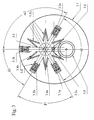
- Figure 3 shows a third embodiment of the detector, with the same components as in Fig. 2, but in another geometric arrangement. To illustrate this, is the first digit of the respective reference instead of "2" here "3".
- the two LEDs and the two photodiodes are not reversed be arranged, because in this case would the two photodiodes simultaneously the forward scattered radiation the one LED and then the reverse scattered radiation the other LED measure, so four Deliver readings, but two in pairs at least approximately the same.
- the stray radiation measured at angles of 120 ° and 60 °, respectively.
- compliance with these angles is not necessary Condition for carrying out the proposed with the invention Process.
- the only important thing is that the Angle be chosen so that in forward scatter direction and sufficient in reverse direction on the one hand high intensities, on the other hand for as many different Brand-following products sufficiently different Intensities in the forward scattering area and in the backward scattering area of the particles concerned.
Applications Claiming Priority (2)
| Application Number | Priority Date | Filing Date | Title |
|---|---|---|---|
| DE10246756 | 2002-10-07 | ||
| DE10246756A DE10246756B4 (de) | 2002-10-07 | 2002-10-07 | Branderkennungsverfahren und Brandmelder zu dessen Durchführung |
Publications (3)
| Publication Number | Publication Date |
|---|---|
| EP1408469A2 true EP1408469A2 (fr) | 2004-04-14 |
| EP1408469A3 EP1408469A3 (fr) | 2004-07-14 |
| EP1408469B1 EP1408469B1 (fr) | 2009-05-27 |
Family
ID=32010359
Family Applications (1)
| Application Number | Title | Priority Date | Filing Date |
|---|---|---|---|
| EP03013270A Expired - Lifetime EP1408469B1 (fr) | 2002-10-07 | 2003-06-12 | Méthode de détection de feux, ainsi que détecteur pour son implémentation |
Country Status (7)
| Country | Link |
|---|---|
| US (2) | US7239387B2 (fr) |
| EP (1) | EP1408469B1 (fr) |
| AT (1) | ATE432518T1 (fr) |
| DE (2) | DE10246756B4 (fr) |
| ES (1) | ES2326631T3 (fr) |
| HK (1) | HK1060426A1 (fr) |
| TW (1) | TW200532593A (fr) |
Cited By (8)
| Publication number | Priority date | Publication date | Assignee | Title |
|---|---|---|---|---|
| EP1879158A1 (fr) * | 2006-07-14 | 2008-01-16 | Siemens Schweiz AG | Procédé de détection de fumée et détecteur de fumée optique |
| WO2008006578A1 (fr) | 2006-07-12 | 2008-01-17 | Hochschule Für Technik Und Wirtschaft Des Saarlandes | Dispositif et procédé de distinction de types de brouillards |
| EP1887536A1 (fr) * | 2006-08-09 | 2008-02-13 | Siemens Schweiz AG | Détecteur de fumée à lumière diffusée |
| EP2706515A1 (fr) * | 2012-09-07 | 2014-03-12 | Amrona AG | Dispositif et procédé de détection de signaux de lumière diffusée |
| DE202015000820U1 (de) | 2014-12-01 | 2015-03-04 | Siemens Schweiz Ag | Streulichtrauchmelder mit zwei zweifarbigen Leuchtdioden und einem gemeinsamen Photosensor oder mit einer zweifarbigen Leuchtdiode und mit zwei Photosensoren jeweils in einer Vorwärts- und Rückwärtsstreulichtanordnung |
| US9036150B2 (en) | 2011-11-25 | 2015-05-19 | Apparatebau Gauting Gmbh | Scattered radiation fire detector and method for the automatic detection of a fire situation |
| EP3287999A1 (fr) | 2016-08-25 | 2018-02-28 | Siemens Schweiz AG | Procede de detection d'incendie selon le principe de diffusion de la lumiere avec connexion echelonnee d'une autre unite a del pour emettre d'autres impulsions de lumiere de differentes longueurs d'onde et angle de diffusion de lumiere et un tel detecteur de fumee a ecran diffusant |
| EP3321906A1 (fr) * | 2016-11-11 | 2018-05-16 | Kidde Technologies, Inc. | Détection à base de fibres optiques à haute sensibilité |
Families Citing this family (28)
| Publication number | Priority date | Publication date | Assignee | Title |
|---|---|---|---|---|
| US7111496B1 (en) * | 2004-04-29 | 2006-09-26 | Pedro Lilienfeld | Methods and apparatus for monitoring a mass concentration of particulate matter |
| EP1619640A1 (fr) * | 2004-07-23 | 2006-01-25 | Siemens Schweiz AG | Detecteur de fumée à lumière diffusée |
| EP1630758B1 (fr) * | 2004-08-31 | 2008-01-02 | Siemens Schweiz AG | Capteur de fumée à lumière disperse |
| DE102007013295A1 (de) | 2007-03-16 | 2008-09-18 | Aoa Apparatebau Gauting Gmbh | Rauchmelder |
| AU2015224408B2 (en) * | 2008-09-05 | 2016-05-26 | Garrett Thermal Systems Limited | Optical detection of particle characteristics |
| AU2009290147C1 (en) | 2008-09-05 | 2016-01-21 | Garrett Thermal Systems Limited | Optical detection of particle characteristics |
| US8717181B2 (en) | 2010-07-29 | 2014-05-06 | Hill-Rom Services, Inc. | Bed exit alert silence with automatic re-enable |
| JP5853143B2 (ja) * | 2011-03-11 | 2016-02-09 | パナソニックIpマネジメント株式会社 | 火災感知器 |
| DE102011108390B4 (de) | 2011-07-22 | 2019-07-11 | PPP "KB Pribor" Ltd. | Verfahren zur Herstellung eines Rauchdetektors vom offenen Typ |
| DE102011108389A1 (de) | 2011-07-22 | 2013-01-24 | PPP "KB Pribor" Ltd. | Rauchdetektor |
| GB2499256A (en) | 2012-02-13 | 2013-08-14 | Thorn Security | Fire detector sensing photo-luminescent emissions from illuminated particles |
| US8952821B2 (en) * | 2012-04-29 | 2015-02-10 | Valor Fire Safety, Llc | Smoke detector utilizing ambient-light sensor, external sampling volume, and internally reflected light |
| DE102013201049A1 (de) * | 2013-01-23 | 2014-07-24 | Robert Bosch Gmbh | Brandmelder |
| JP6407295B2 (ja) | 2013-10-30 | 2018-10-17 | ヴァラー ファイヤー セーフティー, エルエルシー | 外部サンプリング体積および周囲光拒絶を有する煙検出器 |
| US9355542B2 (en) * | 2014-01-27 | 2016-05-31 | Kidde Technologies, Inc. | Apparatuses, systems and methods for self-testing optical fire detectors |
| ES2721929T3 (es) * | 2014-12-01 | 2019-08-06 | Siemens Schweiz Ag | Detector de humo de luz dispersa con un diodo emisor de luz de dos colores |
| JP6315641B2 (ja) * | 2015-06-23 | 2018-04-25 | 華中科技大学 | 2波長の散乱光信号に基づくエアロゾルの特徴パラメータの取得方法及びその使用 |
| US11087605B2 (en) | 2016-06-15 | 2021-08-10 | Carrier Corporation | Smoke detection methodology |
| WO2018027104A1 (fr) * | 2016-08-04 | 2018-02-08 | Carrier Corporation | Détecteur de fumée |
| WO2018226567A1 (fr) | 2017-06-09 | 2018-12-13 | Carrier Corporation | Détecteur de fumée sans chambre avec détection et surveillance de la qualité de l'air intérieur |
| JP7320959B2 (ja) * | 2019-03-11 | 2023-08-04 | 能美防災株式会社 | 煙感知器 |
| US10697880B1 (en) * | 2019-04-07 | 2020-06-30 | Everday Technology Co., Ltd. | Smoke detecting device |
| CN109949534A (zh) * | 2019-04-19 | 2019-06-28 | 汉威科技集团股份有限公司 | 一种多光路双向散射感烟探测器迷宫 |
| US10950108B2 (en) * | 2019-08-09 | 2021-03-16 | Rosemount Aerospace Inc. | Characterization of aerosols |
| CN112562253B (zh) * | 2019-09-26 | 2022-06-03 | 杭州海康消防科技有限公司 | 一种烟雾传感器、烟雾报警方法及装置 |
| US11127284B1 (en) | 2020-07-02 | 2021-09-21 | Honeywell International Inc. | Self-calibrating fire sensing device |
| US11506586B2 (en) | 2020-08-17 | 2022-11-22 | Carrier Corporation | Photoelectric smoke sensor tube |
| CN112991666B (zh) * | 2021-02-08 | 2023-04-28 | 三明学院 | 一种火灾烟雾探测器及其烟室和抗干扰烟雾探测方法 |
Citations (3)
| Publication number | Priority date | Publication date | Assignee | Title |
|---|---|---|---|---|
| US5280272A (en) * | 1991-09-20 | 1994-01-18 | Hochiki Kabushiki Kaisha | Fire alarm system which distinguishes between different types of smoke |
| WO2000007161A1 (fr) * | 1998-07-31 | 2000-02-10 | Gsbs Development Corporation | Detecteur de fumee |
| US6218950B1 (en) * | 1999-01-21 | 2001-04-17 | Caradon Esser Gmbh | Scattered light fire detector |
Family Cites Families (15)
| Publication number | Priority date | Publication date | Assignee | Title |
|---|---|---|---|---|
| US3982130A (en) * | 1975-10-10 | 1976-09-21 | The United States Of America As Represented By The Secretary Of The Air Force | Ultraviolet wavelength smoke detector |
| SE7905294L (sv) * | 1979-06-15 | 1980-12-16 | Svenska Traeforskningsinst | Stoftmetning |
| US5051595A (en) * | 1989-12-06 | 1991-09-24 | Santa Barbara Research Center | Fiber optic flame detection and temperature measurement system employing doped optical fiber |
| US5352901A (en) * | 1993-04-26 | 1994-10-04 | Cummins Electronics Company, Inc. | Forward and back scattering loss compensated smoke detector |
| US5575837A (en) * | 1993-04-28 | 1996-11-19 | Fujimi Incorporated | Polishing composition |
| US5527423A (en) * | 1994-10-06 | 1996-06-18 | Cabot Corporation | Chemical mechanical polishing slurry for metal layers |
| US6117783A (en) * | 1996-07-25 | 2000-09-12 | Ekc Technology, Inc. | Chemical mechanical polishing composition and process |
| US5958288A (en) * | 1996-11-26 | 1999-09-28 | Cabot Corporation | Composition and slurry useful for metal CMP |
| JPH1123458A (ja) * | 1997-05-08 | 1999-01-29 | Nittan Co Ltd | 煙感知器および監視制御システム |
| US6001269A (en) * | 1997-05-20 | 1999-12-14 | Rodel, Inc. | Method for polishing a composite comprising an insulator, a metal, and titanium |
| US6083419A (en) * | 1997-07-28 | 2000-07-04 | Cabot Corporation | Polishing composition including an inhibitor of tungsten etching |
| US7126687B2 (en) * | 1999-08-09 | 2006-10-24 | The United States Of America As Represented By The Secretary Of The Army | Method and instrumentation for determining absorption and morphology of individual airborne particles |
| AUPQ553800A0 (en) * | 2000-02-10 | 2000-03-02 | Cole, Martin Terence | Improvements relating to smoke detectors particularily duct monitored smoke detectors |
| JP4954398B2 (ja) * | 2001-08-09 | 2012-06-13 | 株式会社フジミインコーポレーテッド | 研磨用組成物およびそれを用いた研磨方法 |
| GB2397122B (en) | 2003-01-03 | 2006-02-08 | David Appleby | Fire detector with low false alarm rate |
-
2002
- 2002-10-07 DE DE10246756A patent/DE10246756B4/de not_active Expired - Lifetime
-
2003
- 2003-06-12 AT AT03013270T patent/ATE432518T1/de active
- 2003-06-12 DE DE50311545T patent/DE50311545D1/de not_active Expired - Lifetime
- 2003-06-12 ES ES03013270T patent/ES2326631T3/es not_active Expired - Lifetime
- 2003-06-12 EP EP03013270A patent/EP1408469B1/fr not_active Expired - Lifetime
- 2003-08-26 US US10/647,318 patent/US7239387B2/en active Active
-
2004
- 2004-03-16 TW TW093106965A patent/TW200532593A/zh unknown
- 2004-05-13 HK HK04103368.4A patent/HK1060426A1/xx not_active IP Right Cessation
-
2007
- 2007-06-07 US US11/759,264 patent/US7298479B2/en not_active Expired - Lifetime
Patent Citations (3)
| Publication number | Priority date | Publication date | Assignee | Title |
|---|---|---|---|---|
| US5280272A (en) * | 1991-09-20 | 1994-01-18 | Hochiki Kabushiki Kaisha | Fire alarm system which distinguishes between different types of smoke |
| WO2000007161A1 (fr) * | 1998-07-31 | 2000-02-10 | Gsbs Development Corporation | Detecteur de fumee |
| US6218950B1 (en) * | 1999-01-21 | 2001-04-17 | Caradon Esser Gmbh | Scattered light fire detector |
Non-Patent Citations (1)
| Title |
|---|
| GOODMAN D S: "METHOD FOR LOCALIZING LIGHT-SCATTERED PARTICLES" IBM TECHNICAL DISCLOSURE BULLETIN, IBM CORP. NEW YORK, US, Bd. 27, Nr. 5, 1. Oktober 1984 (1984-10-01), Seite 3164, XP002066860 ISSN: 0018-8689 * |
Cited By (19)
| Publication number | Priority date | Publication date | Assignee | Title |
|---|---|---|---|---|
| WO2008006578A1 (fr) | 2006-07-12 | 2008-01-17 | Hochschule Für Technik Und Wirtschaft Des Saarlandes | Dispositif et procédé de distinction de types de brouillards |
| EP1879158A1 (fr) * | 2006-07-14 | 2008-01-16 | Siemens Schweiz AG | Procédé de détection de fumée et détecteur de fumée optique |
| EP1887536A1 (fr) * | 2006-08-09 | 2008-02-13 | Siemens Schweiz AG | Détecteur de fumée à lumière diffusée |
| WO2008017698A1 (fr) * | 2006-08-09 | 2008-02-14 | Siemens Schweiz Ag | Détecteur de fumée à lumière diffuse |
| US9036150B2 (en) | 2011-11-25 | 2015-05-19 | Apparatebau Gauting Gmbh | Scattered radiation fire detector and method for the automatic detection of a fire situation |
| EP2706515A1 (fr) * | 2012-09-07 | 2014-03-12 | Amrona AG | Dispositif et procédé de détection de signaux de lumière diffusée |
| US9244010B2 (en) | 2012-09-07 | 2016-01-26 | Amrona Ag | Device and method for detecting scattered light signals |
| CN103782327A (zh) * | 2012-09-07 | 2014-05-07 | 艾摩罗那股份公司 | 用于检测散射光信号的设备和方法 |
| WO2014037520A1 (fr) * | 2012-09-07 | 2014-03-13 | Amrona Ag | Dispositif et procédé de détection de signaux de lumière diffusée |
| EP2839448B1 (fr) | 2012-09-07 | 2015-07-22 | Amrona AG | Dispositif et procédé de détection de signaux de lumière diffusée |
| CN103782327B (zh) * | 2012-09-07 | 2015-08-05 | 艾摩罗那股份公司 | 用于检测散射光信号的设备和方法 |
| EP3029648A1 (fr) | 2014-12-01 | 2016-06-08 | Siemens Schweiz AG | Détecteur de fumée à écran diffusant doté de deux diodes lumineuses bicolores et d'un photo-capteur commun ou d'une diode lumineuse bicolore et de deux photo-capteurs chacun dans une disposition avant et arrière de lumière diffusée |
| DE202015000820U1 (de) | 2014-12-01 | 2015-03-04 | Siemens Schweiz Ag | Streulichtrauchmelder mit zwei zweifarbigen Leuchtdioden und einem gemeinsamen Photosensor oder mit einer zweifarbigen Leuchtdiode und mit zwei Photosensoren jeweils in einer Vorwärts- und Rückwärtsstreulichtanordnung |
| EP3287999A1 (fr) | 2016-08-25 | 2018-02-28 | Siemens Schweiz AG | Procede de detection d'incendie selon le principe de diffusion de la lumiere avec connexion echelonnee d'une autre unite a del pour emettre d'autres impulsions de lumiere de differentes longueurs d'onde et angle de diffusion de lumiere et un tel detecteur de fumee a ecran diffusant |
| WO2018036754A1 (fr) | 2016-08-25 | 2018-03-01 | Siemens Schweiz Ag | Procédé de détection d'incendie selon le principe de lumière diffusée avec allumage échelonné d'une autre unité de del pour rayonner d'autres impulsions lumineuses de différentes longueurs d'onde et selon d'autres angles de diffusion ainsi que détecteur de fumées à lumière diffusée |
| CN109601019A (zh) * | 2016-08-25 | 2019-04-09 | 西门子瑞士有限公司 | 用于根据散射光原理、借助用于使不同波长和散射光角度的另外的光脉冲入射的另外的led单元交错地接通来进行火灾探测的方法以及这样的散射光烟雾报警器 |
| US10685546B2 (en) | 2016-08-25 | 2020-06-16 | Siemens Schweiz Ag | Fire detection using the scattered light principle with a staggered activation of a further LED unit for radiating in further light pulses with different wavelengths and scattered light angles |
| EP3321906A1 (fr) * | 2016-11-11 | 2018-05-16 | Kidde Technologies, Inc. | Détection à base de fibres optiques à haute sensibilité |
| CN108072596A (zh) * | 2016-11-11 | 2018-05-25 | 基德科技公司 | 基于高灵敏度光纤的检测 |
Also Published As
| Publication number | Publication date |
|---|---|
| US7298479B2 (en) | 2007-11-20 |
| EP1408469A3 (fr) | 2004-07-14 |
| US20070229824A1 (en) | 2007-10-04 |
| ES2326631T3 (es) | 2009-10-16 |
| EP1408469B1 (fr) | 2009-05-27 |
| TW200532593A (en) | 2005-10-01 |
| US20040066512A1 (en) | 2004-04-08 |
| US7239387B2 (en) | 2007-07-03 |
| DE10246756A1 (de) | 2004-04-22 |
| HK1060426A1 (en) | 2004-08-06 |
| DE50311545D1 (de) | 2009-07-09 |
| DE10246756B4 (de) | 2006-03-16 |
| ATE432518T1 (de) | 2009-06-15 |
Similar Documents
| Publication | Publication Date | Title |
|---|---|---|
| EP1408469B1 (fr) | Méthode de détection de feux, ainsi que détecteur pour son implémentation | |
| DE60315449T2 (de) | Rauchmelder | |
| EP2706515B1 (fr) | Dispositif et procédé de détection de signaux de lumière diffusée | |
| DE2504300C3 (de) | Vorrichtung zur Messung des Absorptionsvermögens eines Mediums, insbesondere von Rauch | |
| EP3504692B1 (fr) | Procede de detection d'incendie selon le principe de diffusion de la lumiere avec connexion echelonnee d'une autre unite a del pour emettre d'autres impulsions de lumiere de differentes longueurs d'onde et angle de diffusion de lumiere et un tel detecteur de fumee a ecran diffusant | |
| DE102011119431B4 (de) | Streustrahlungsbrandmelder und Verfahren zur automatischen Erkennung einer Brandsituation | |
| DE3831654C2 (fr) | ||
| EP0617389B1 (fr) | Détecteur d'intrusion | |
| DE2358449B2 (de) | Verfahren zur Brandmeldung und Brandmelder zur Durchführung des Verfahrens | |
| EP3504535B1 (fr) | Dispositif de mesure pour mesure de l'absorption des gaz | |
| CH683464A5 (de) | Optischer Rauchmelder mit aktiver Ueberwachung. | |
| EP1062647B1 (fr) | Avertisseur d'incendie | |
| EP2533032A1 (fr) | Procédé de mesure et dispositif de mesure destinés à déterminer les propriétés de transmission et/ou réflexion | |
| WO2016074773A1 (fr) | Capteur de gaz optique à émetteur à del pour émission de lumière à largeur de bande étroite | |
| WO1999016033A1 (fr) | Detecteur de fumee | |
| WO2019086552A1 (fr) | Capteur novateur pour spectroscopie raman | |
| EP3096130B1 (fr) | Dispositif destine a l'identification d'aerosols | |
| DE102006048839B4 (de) | Photoakustische Gassensor-Vorrichtung mit mehreren Messzellen | |
| DE3917571C2 (fr) | ||
| DE102004001357A1 (de) | Ölnebel-Erkennungseinrichtung | |
| DE10239616C1 (de) | Verfahren zur photoelektrischen Überwachung von Wasser auf Ölanteile | |
| DE3018021C2 (fr) | ||
| DE112020002849T5 (de) | Optischer Partikelsensor | |
| DE102020211328A1 (de) | Optischer Rußpartikelsensor | |
| DE102020202824A1 (de) | Sensorvorrichtung unter verwendung der winkelabhängigkeit eines dichroitischen filters |
Legal Events
| Date | Code | Title | Description |
|---|---|---|---|
| PUAI | Public reference made under article 153(3) epc to a published international application that has entered the european phase |
Free format text: ORIGINAL CODE: 0009012 |
|
| AK | Designated contracting states |
Kind code of ref document: A2 Designated state(s): AT BE BG CH CY CZ DE DK EE ES FI FR GB GR HU IE IT LI LU MC NL PT RO SE SI SK TR |
|
| AX | Request for extension of the european patent |
Extension state: AL LT LV MK |
|
| PUAL | Search report despatched |
Free format text: ORIGINAL CODE: 0009013 |
|
| AK | Designated contracting states |
Kind code of ref document: A3 Designated state(s): AT BE BG CH CY CZ DE DK EE ES FI FR GB GR HU IE IT LI LU MC NL PT RO SE SI SK TR |
|
| AX | Request for extension of the european patent |
Extension state: AL LT LV MK |
|
| REG | Reference to a national code |
Ref country code: HK Ref legal event code: DE Ref document number: 1060426 Country of ref document: HK |
|
| 17P | Request for examination filed |
Effective date: 20040715 |
|
| AKX | Designation fees paid |
Designated state(s): AT BE BG CH CY CZ DE DK EE ES FI FR GB GR HU IE IT LI LU MC NL PT RO SE SI SK TR |
|
| 17Q | First examination report despatched |
Effective date: 20060802 |
|
| GRAP | Despatch of communication of intention to grant a patent |
Free format text: ORIGINAL CODE: EPIDOSNIGR1 |
|
| GRAS | Grant fee paid |
Free format text: ORIGINAL CODE: EPIDOSNIGR3 |
|
| GRAA | (expected) grant |
Free format text: ORIGINAL CODE: 0009210 |
|
| AK | Designated contracting states |
Kind code of ref document: B1 Designated state(s): AT BE BG CH CY CZ DE DK EE ES FI FR GB GR HU IE IT LI LU MC NL PT RO SE SI SK TR |
|
| REG | Reference to a national code |
Ref country code: GB Ref legal event code: FG4D Free format text: NOT ENGLISH |
|
| REG | Reference to a national code |
Ref country code: CH Ref legal event code: EP |
|
| REG | Reference to a national code |
Ref country code: IE Ref legal event code: FG4D Free format text: LANGUAGE OF EP DOCUMENT: GERMAN |
|
| REF | Corresponds to: |
Ref document number: 50311545 Country of ref document: DE Date of ref document: 20090709 Kind code of ref document: P |
|
| REG | Reference to a national code |
Ref country code: HK Ref legal event code: GR Ref document number: 1060426 Country of ref document: HK |
|
| REG | Reference to a national code |
Ref country code: ES Ref legal event code: FG2A Ref document number: 2326631 Country of ref document: ES Kind code of ref document: T3 |
|
| PG25 | Lapsed in a contracting state [announced via postgrant information from national office to epo] |
Ref country code: PT Free format text: LAPSE BECAUSE OF FAILURE TO SUBMIT A TRANSLATION OF THE DESCRIPTION OR TO PAY THE FEE WITHIN THE PRESCRIBED TIME-LIMIT Effective date: 20090927 Ref country code: FI Free format text: LAPSE BECAUSE OF FAILURE TO SUBMIT A TRANSLATION OF THE DESCRIPTION OR TO PAY THE FEE WITHIN THE PRESCRIBED TIME-LIMIT Effective date: 20090527 |
|
| NLV1 | Nl: lapsed or annulled due to failure to fulfill the requirements of art. 29p and 29m of the patents act | ||
| PG25 | Lapsed in a contracting state [announced via postgrant information from national office to epo] |
Ref country code: SI Free format text: LAPSE BECAUSE OF FAILURE TO SUBMIT A TRANSLATION OF THE DESCRIPTION OR TO PAY THE FEE WITHIN THE PRESCRIBED TIME-LIMIT Effective date: 20090527 Ref country code: SE Free format text: LAPSE BECAUSE OF FAILURE TO SUBMIT A TRANSLATION OF THE DESCRIPTION OR TO PAY THE FEE WITHIN THE PRESCRIBED TIME-LIMIT Effective date: 20090827 Ref country code: NL Free format text: LAPSE BECAUSE OF FAILURE TO SUBMIT A TRANSLATION OF THE DESCRIPTION OR TO PAY THE FEE WITHIN THE PRESCRIBED TIME-LIMIT Effective date: 20090527 |
|
| BERE | Be: lapsed |
Owner name: NOVAR G.M.B.H. Effective date: 20090630 |
|
| REG | Reference to a national code |
Ref country code: IE Ref legal event code: FD4D |
|
| PG25 | Lapsed in a contracting state [announced via postgrant information from national office to epo] |
Ref country code: EE Free format text: LAPSE BECAUSE OF FAILURE TO SUBMIT A TRANSLATION OF THE DESCRIPTION OR TO PAY THE FEE WITHIN THE PRESCRIBED TIME-LIMIT Effective date: 20090527 Ref country code: DK Free format text: LAPSE BECAUSE OF FAILURE TO SUBMIT A TRANSLATION OF THE DESCRIPTION OR TO PAY THE FEE WITHIN THE PRESCRIBED TIME-LIMIT Effective date: 20090527 Ref country code: CZ Free format text: LAPSE BECAUSE OF FAILURE TO SUBMIT A TRANSLATION OF THE DESCRIPTION OR TO PAY THE FEE WITHIN THE PRESCRIBED TIME-LIMIT Effective date: 20090527 Ref country code: IE Free format text: LAPSE BECAUSE OF FAILURE TO SUBMIT A TRANSLATION OF THE DESCRIPTION OR TO PAY THE FEE WITHIN THE PRESCRIBED TIME-LIMIT Effective date: 20090527 Ref country code: MC Free format text: LAPSE BECAUSE OF NON-PAYMENT OF DUE FEES Effective date: 20090630 Ref country code: RO Free format text: LAPSE BECAUSE OF FAILURE TO SUBMIT A TRANSLATION OF THE DESCRIPTION OR TO PAY THE FEE WITHIN THE PRESCRIBED TIME-LIMIT Effective date: 20090527 |
|
| REG | Reference to a national code |
Ref country code: CH Ref legal event code: PL |
|
| PG25 | Lapsed in a contracting state [announced via postgrant information from national office to epo] |
Ref country code: SK Free format text: LAPSE BECAUSE OF FAILURE TO SUBMIT A TRANSLATION OF THE DESCRIPTION OR TO PAY THE FEE WITHIN THE PRESCRIBED TIME-LIMIT Effective date: 20090527 |
|
| PG25 | Lapsed in a contracting state [announced via postgrant information from national office to epo] |
Ref country code: BG Free format text: LAPSE BECAUSE OF FAILURE TO SUBMIT A TRANSLATION OF THE DESCRIPTION OR TO PAY THE FEE WITHIN THE PRESCRIBED TIME-LIMIT Effective date: 20090827 |
|
| PLBE | No opposition filed within time limit |
Free format text: ORIGINAL CODE: 0009261 |
|
| STAA | Information on the status of an ep patent application or granted ep patent |
Free format text: STATUS: NO OPPOSITION FILED WITHIN TIME LIMIT |
|
| PG25 | Lapsed in a contracting state [announced via postgrant information from national office to epo] |
Ref country code: CH Free format text: LAPSE BECAUSE OF NON-PAYMENT OF DUE FEES Effective date: 20090630 Ref country code: LI Free format text: LAPSE BECAUSE OF NON-PAYMENT OF DUE FEES Effective date: 20090630 |
|
| 26N | No opposition filed |
Effective date: 20100302 |
|
| PG25 | Lapsed in a contracting state [announced via postgrant information from national office to epo] |
Ref country code: BE Free format text: LAPSE BECAUSE OF NON-PAYMENT OF DUE FEES Effective date: 20090630 |
|
| PG25 | Lapsed in a contracting state [announced via postgrant information from national office to epo] |
Ref country code: GR Free format text: LAPSE BECAUSE OF FAILURE TO SUBMIT A TRANSLATION OF THE DESCRIPTION OR TO PAY THE FEE WITHIN THE PRESCRIBED TIME-LIMIT Effective date: 20090828 |
|
| PG25 | Lapsed in a contracting state [announced via postgrant information from national office to epo] |
Ref country code: LU Free format text: LAPSE BECAUSE OF NON-PAYMENT OF DUE FEES Effective date: 20090612 |
|
| PG25 | Lapsed in a contracting state [announced via postgrant information from national office to epo] |
Ref country code: HU Free format text: LAPSE BECAUSE OF FAILURE TO SUBMIT A TRANSLATION OF THE DESCRIPTION OR TO PAY THE FEE WITHIN THE PRESCRIBED TIME-LIMIT Effective date: 20091128 |
|
| PG25 | Lapsed in a contracting state [announced via postgrant information from national office to epo] |
Ref country code: TR Free format text: LAPSE BECAUSE OF FAILURE TO SUBMIT A TRANSLATION OF THE DESCRIPTION OR TO PAY THE FEE WITHIN THE PRESCRIBED TIME-LIMIT Effective date: 20090527 |
|
| PG25 | Lapsed in a contracting state [announced via postgrant information from national office to epo] |
Ref country code: CY Free format text: LAPSE BECAUSE OF FAILURE TO SUBMIT A TRANSLATION OF THE DESCRIPTION OR TO PAY THE FEE WITHIN THE PRESCRIBED TIME-LIMIT Effective date: 20090527 |
|
| REG | Reference to a national code |
Ref country code: DE Ref legal event code: R082 Ref document number: 50311545 Country of ref document: DE Representative=s name: PATENTANWAELTE HENKEL, BREUER & PARTNER, DE Ref country code: DE Ref legal event code: R082 Ref document number: 50311545 Country of ref document: DE Representative=s name: PATENTANWAELTE HENKEL, BREUER & PARTNER MBB, DE |
|
| REG | Reference to a national code |
Ref country code: FR Ref legal event code: PLFP Year of fee payment: 14 |
|
| REG | Reference to a national code |
Ref country code: FR Ref legal event code: PLFP Year of fee payment: 15 |
|
| REG | Reference to a national code |
Ref country code: FR Ref legal event code: PLFP Year of fee payment: 16 |
|
| PGFP | Annual fee paid to national office [announced via postgrant information from national office to epo] |
Ref country code: IT Payment date: 20180625 Year of fee payment: 9 Ref country code: ES Payment date: 20180723 Year of fee payment: 16 |
|
| REG | Reference to a national code |
Ref country code: AT Ref legal event code: MM01 Ref document number: 432518 Country of ref document: AT Kind code of ref document: T Effective date: 20190612 |
|
| PG25 | Lapsed in a contracting state [announced via postgrant information from national office to epo] |
Ref country code: AT Free format text: LAPSE BECAUSE OF NON-PAYMENT OF DUE FEES Effective date: 20190612 Ref country code: IT Free format text: LAPSE BECAUSE OF NON-PAYMENT OF DUE FEES Effective date: 20190612 |
|
| PGFP | Annual fee paid to national office [announced via postgrant information from national office to epo] |
Ref country code: FR Payment date: 20200626 Year of fee payment: 18 |
|
| REG | Reference to a national code |
Ref country code: ES Ref legal event code: FD2A Effective date: 20201027 |
|
| PGFP | Annual fee paid to national office [announced via postgrant information from national office to epo] |
Ref country code: DE Payment date: 20200630 Year of fee payment: 18 |
|
| PG25 | Lapsed in a contracting state [announced via postgrant information from national office to epo] |
Ref country code: ES Free format text: LAPSE BECAUSE OF NON-PAYMENT OF DUE FEES Effective date: 20190613 |
|
| REG | Reference to a national code |
Ref country code: DE Ref legal event code: R119 Ref document number: 50311545 Country of ref document: DE |
|
| PG25 | Lapsed in a contracting state [announced via postgrant information from national office to epo] |
Ref country code: DE Free format text: LAPSE BECAUSE OF NON-PAYMENT OF DUE FEES Effective date: 20220101 |
|
| PG25 | Lapsed in a contracting state [announced via postgrant information from national office to epo] |
Ref country code: FR Free format text: LAPSE BECAUSE OF NON-PAYMENT OF DUE FEES Effective date: 20210630 |
|
| PGFP | Annual fee paid to national office [announced via postgrant information from national office to epo] |
Ref country code: GB Payment date: 20220621 Year of fee payment: 20 |
|
| P01 | Opt-out of the competence of the unified patent court (upc) registered |
Effective date: 20230523 |
|
| REG | Reference to a national code |
Ref country code: GB Ref legal event code: PE20 Expiry date: 20230611 |
|
| PG25 | Lapsed in a contracting state [announced via postgrant information from national office to epo] |
Ref country code: GB Free format text: LAPSE BECAUSE OF EXPIRATION OF PROTECTION Effective date: 20230611 |