EP1408321B1 - Capteur pour détecter du pollen et procédé - Google Patents
Capteur pour détecter du pollen et procédé Download PDFInfo
- Publication number
- EP1408321B1 EP1408321B1 EP03022585A EP03022585A EP1408321B1 EP 1408321 B1 EP1408321 B1 EP 1408321B1 EP 03022585 A EP03022585 A EP 03022585A EP 03022585 A EP03022585 A EP 03022585A EP 1408321 B1 EP1408321 B1 EP 1408321B1
- Authority
- EP
- European Patent Office
- Prior art keywords
- particles
- receiver
- light beam
- pollen
- polarized
- Prior art date
- Legal status (The legal status is an assumption and is not a legal conclusion. Google has not performed a legal analysis and makes no representation as to the accuracy of the status listed.)
- Expired - Lifetime
Links
- 238000000034 method Methods 0.000 title claims description 17
- 239000002245 particle Substances 0.000 claims description 121
- 230000010287 polarization Effects 0.000 claims description 40
- 238000001514 detection method Methods 0.000 claims description 28
- 238000005286 illumination Methods 0.000 claims description 19
- 230000003287 optical effect Effects 0.000 claims description 14
- 239000004816 latex Substances 0.000 description 7
- 229920000126 latex Polymers 0.000 description 7
- 238000005259 measurement Methods 0.000 description 6
- 239000004033 plastic Substances 0.000 description 5
- 239000004793 Polystyrene Substances 0.000 description 4
- 238000006243 chemical reaction Methods 0.000 description 4
- 229920002223 polystyrene Polymers 0.000 description 4
- 241000218692 Cryptomeria Species 0.000 description 3
- 238000011179 visual inspection Methods 0.000 description 3
- 238000011109 contamination Methods 0.000 description 2
- 239000006185 dispersion Substances 0.000 description 2
- 239000011521 glass Substances 0.000 description 2
- 238000005070 sampling Methods 0.000 description 2
- 239000004065 semiconductor Substances 0.000 description 2
- 201000010105 allergic rhinitis Diseases 0.000 description 1
- 238000004458 analytical method Methods 0.000 description 1
- 230000000052 comparative effect Effects 0.000 description 1
- 230000007812 deficiency Effects 0.000 description 1
- 238000010586 diagram Methods 0.000 description 1
- 230000000694 effects Effects 0.000 description 1
- 238000010223 real-time analysis Methods 0.000 description 1
Images

Classifications
-
- G—PHYSICS
- G01—MEASURING; TESTING
- G01N—INVESTIGATING OR ANALYSING MATERIALS BY DETERMINING THEIR CHEMICAL OR PHYSICAL PROPERTIES
- G01N21/00—Investigating or analysing materials by the use of optical means, i.e. using sub-millimetre waves, infrared, visible or ultraviolet light
- G01N21/17—Systems in which incident light is modified in accordance with the properties of the material investigated
- G01N21/21—Polarisation-affecting properties
-
- G—PHYSICS
- G01—MEASURING; TESTING
- G01N—INVESTIGATING OR ANALYSING MATERIALS BY DETERMINING THEIR CHEMICAL OR PHYSICAL PROPERTIES
- G01N15/00—Investigating characteristics of particles; Investigating permeability, pore-volume or surface-area of porous materials
- G01N15/02—Investigating particle size or size distribution
- G01N15/0205—Investigating particle size or size distribution by optical means
- G01N15/0211—Investigating a scatter or diffraction pattern
-
- G—PHYSICS
- G01—MEASURING; TESTING
- G01N—INVESTIGATING OR ANALYSING MATERIALS BY DETERMINING THEIR CHEMICAL OR PHYSICAL PROPERTIES
- G01N15/00—Investigating characteristics of particles; Investigating permeability, pore-volume or surface-area of porous materials
- G01N2015/0042—Investigating dispersion of solids
- G01N2015/0046—Investigating dispersion of solids in gas, e.g. smoke
Definitions
- the present invention relates to a pollen sensor and method for detecting pollen particles and discriminating pollen particles floating in air from other particles on a real time basis. More specifically, the pollen sensor and method detects pollen particles floating in air, which can be a cause for pollenosis.
- a microscope has been used to detect the number of pollen particles floating in air using a visual inspection process in which a glass plate is exposed to air for some time to collect pollen particles.
- the glass plate is stained, followed by a skilled technician's counting by visual inspection the stained particles through his or her microscope (hereinafter referred to as the "microscope method").
- the above microscope method is a lengthy time consuming process requiring advanced skills to count the stained pollen particles by visual inspection.
- the microscope method does not permit pollen particles to be detected on a real time basis which is a significant drawback.
- the place for taking measurements using a microscope is also very limited, which is another drawback.
- a similar detection device is described in Japanese Patent Publication No. 2001-83079 which is capable of measuring floating particles in real time. This device cannot discriminate pollen particles from other particles passed through the detection zone when the volume of air blown into the detection zone is increased. Accordingly, this device has the same deficiencies as the pollen sensor described in Japanese Patent No. 5240768.
- the present invention is based on the discovery that the degree of polarization of scattered light beams from pollen particles is smaller than the degree of polarization from other floating particles even of the same particle size as pollen particles. This principal is used in the pollen sensor of the present invention to discriminate pollen particles from other floating particles.
- the pollen sensor of the present invention comprises: an illumination portion for illuminating particles floating in air using light beams polarized in a given direction; a first receiver for selectively measuring the intensity (Ip) of a light beam from a detection zone polarized parallel to the light beam polarized in a given direction from the illumination portion with the light beam selected from a group of light beams scattered by the floating particles; a second receiver for selectively measuring the intensity (Is) of light beam from a detection zone polarized perpendicular to the light beam polarized in a given direction from the illumination portion with the light beam selected from a group of light beams scattered by the floating particles and means for discriminating pollen particles from other floating particles including means for computing the degree of polarization of such particles as an arithmetic value from the intensity (Ip) of the polarized light beam detected by the first receiver and the intensity (Is) of the polarized light beam detected by the second receiver.
- the pollen sensor comprises: an illumination portion for illuminating particles floating in air using a light beam polarized in a given direction; a first receiver for measuring the intensity (I) of a light beam corresponding to the dispersion of the light beam scattered by the floating particles; a second receiver for selectively measuring the intensity (Is) of light beams polarized perpendicular to light illuminated by the illumination portion from a group of light beams scattered by the floating particles; means for discriminating pollen particles from other floating particles from the degree of polarization of such particles computed from the intensity (I) of the scattered light beam detected by the first receiver and the intensity (Is) of the polarized light beam detected by the second receiver.
- the degree of polarization can be computed either as an arithmetic value using (Ip), which is the intensity of light polarized parallel to the incident polarizing direction and (Is) which is the intensity of light polarized in a direction perpendicular to the incident polarization direction or as an arithmetic value using (I), which is the intensity for all polarized scattered light, and (Is) which is the intensity of light polarized in a direction perpendicular to the incident polarizing direction.
- the degree of polarization may be expressed by the formula (Ip-Is)/(Ip+Is) wherein (Ip) is the intensity of the light beam polarized in the incident polarizing direction and (Is) is the intensity of the light beam polarized perpendicular to the incident polarizing direction.
- the degree of polarization may be expressed by the formula (I-Is)/I wherein (I) is the intensity for all polarized scattered light and (Is) is the intensity of a light beam polarized perpendicular to the incident polarizing direction.
- any person can readily discriminate pollen particles from other floating particles on a real time basis and can perform a real time analysis of the pollen count. Furthermore, the present invention can discriminate pollen particles form other particles notwithstanding the amount of air blown into the detection zone or the number of floating particles passed through the detection zone.
- the present invention can accurately discriminate pollen particles from other particles even though the luminous energy from a light source in the illumination portion weakens over time and / or lens contamination occurs reducing the luminous energy that reaches the detection zone.
- the pollen sensor and method of the present invention permits simultaneous passage of two or more floating particles with a reliable output even if there is a reduction of light volume from light source due to its life problem, or a reduction of dispersion light volume due to the dirt of a lens.
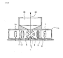
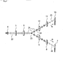
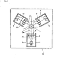
- the pollen sensor of the present invention comprises a shielding housing 14 which forms a confined area for housing an illuminating portion 1 containing a light beam generating source 4, preferably a semiconductor laser diode.
- the light beam generating source generates a light beam 20 for illuminating one or more particles 25 ( Figure 3) floating in air within the detection zone F.
- the light beam 20 has a direction of polarization 22 perpendicular to the plane of the page of Figure 2 as is diagrammatically illustrated in Figure 3.
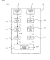
- the pollen sensor further comprises a first receiver 2 having a photodiode 7 aligned in the scattering polarizing direction of the light beam 20, preferably at 60 degrees to the incident optical axis "OA" for measuring the intensity (Ip) of light beams polarized in a direction parallel to the incident polarizing direction of light selected from a group of light beams scattered by the floating particles; a second receiver 3 having a photodiode 10 provided in the scattering polarizing direction, preferably at 60 degrees to the incident optical axis "OA", for measuring the intensity (Is) of light beams in a direction 23 which is polarized perpendicular to the light beam illuminated by the illumination portion selected from a group of light beams scattered by the floating particles and an electronic circuit 32 for discriminating pollen particles from other floating particles.
- a first receiver 2 having a photodiode 7 aligned in the scattering polarizing direction of the light beam 20, preferably at 60 degrees to the incident optical axis "OA" for measuring the intensity (Ip
- the pollen sensor also comprises an air blow port 13 located at the bottom of the shielding housing 14 to direct sampling air drawn from the atmosphere by a fan 26 through the air blow port 13 into the shielding housing 14.
- the sampling air is introduced into the sensor in a direction from the bottom to the top of the plane containing Figure 2.
- Any semiconductor laser diode 4 may be used such as, e.g., an RLD 65 MZT 1, manufactured by Rohm for generating the light beam 20.
- the laser diode 4 is contained in an illuminating portion 1 supported in the housing 14 which, as shown in Figures 1 and 2, also includes a polarizing filter 5 and a plastic lens 6.
- a polarizing filter 5 is the HN 38, manufactured by Polaroid.
- the polarizing filter 5 has a polarizing axis in a direction perpendicular to the plane containing Figure 2 and is perpendicular to the plastic lens 6.
- Lens 6 is arranged in the illuminating portion of the sensor in such a manner that the laser light transmitted through the polarizing filter 5 forms parallel beams of light energy upon reaching the detection zone (F).
- the detection zone F lies at the intersection of the light path through the filter 6 and the light path of the randomly polarized light 24 to the first and second receiver 2 and 3 respectively.
- the polarizing axis of the polarizing filter 8 is perpendicular to the plane containing Figure 2 in the same manner as that of the polarizing filter 5 in the illuminating portion 1 of the pollen sensor.
- a polarizing filter 11 such as e.g., HN 38, manufactured by Polaroid
- a photodiode 10 such as, e.g., S 2506-02 manufactured by Hamamatsu Photonics for measuring light transmitted through the polarizing filter 11.
- the polarizing axis of the polarizing filter 11 is set perpendicular to the polarizing axis of polarizing filter 5, which is in parallel to the plane containing Figure 2.
- the photoelectric current conversion signal Ip and the photoelectric current conversion signal Is are fed to current voltage conversion circuits 35 and 36 respectively, to form voltage signals Vp and Vs respectively.
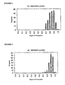
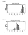
- the computation of the degree of polarization permits a determination to be readily made in accordance with the present invention as to whether the detected particles constitute pollen particles or other floating particles. It has been determined that when the computation of the degree of polarization (Ip - Is)/(Ip + Is) is in the range of 0.35 - 0.75 the detected particles constitute pollen particles. This range of 0.35 - 0.75 may vary with changes in the angle of alignment between the photodiode of the first and second receivers and the axis of the illuminating light beam generating portion (optical axis) which, for the preferred embodiment of the present invention, has been set at 60°.
- Figures 5-8 are histograms illustrating the comparative measurement of the degree of polarization for 20 - micron polystyrene latex particles, 30 - micron polystyrene latex particles, 40 - micron polystyrene latex particles, and for Japanese cedar pollen particles respectively.
- the X-axis shows the degree of polarization (Ip - Is)/(Ip + Is); and the Y-axis shows the frequency of particle detection.
- the range of measurement of the degree of polarization for the latex particles falls between 0.7-1.0 and for the Japanese cedar pollen particles as shown in Figure 8 is between 0.35 - 0.75 permitting a possible overlap in measurement in the range between 0.70 - 0.75.
- FIG 9 is a plan view illustrating the configuration of another embodiment of the pollen sensor of the present invention.
- the pollen sensor in this embodiment excludes filter 8 from the first receiver 2 and is otherwise identical to the pollen sensor in Figure 2.
- the components constituting the same elements as is shown in the sensor of Figure 2 have the same reference symbols.
- light beams scattered from floating particles directly reach photodiode 7 without passing through a polarizing filter.
- an output photoelectric conversion signal I will correspond to the intensity of the scattered light beams for all polarizing directions.
- the degree of polarization for this embodiment is computed in accordance with the formula: (I-Is)/I.
- the degree of polarization falls within the range of 0.35 - 0.75, the particles constitute pollen particles as in the first embodiment and for the same reasons.
- the photodiode 7 in the first receiver 2 and the photodiode 10 in the second receiver 3 were each aligned in the scattering polarization direction at an angle of 60° to the incident optical axis OA, it is not essential to this invention for the angle to be limited to a 60° and, in fact, any angle within a range of 0° - 90° may be used.
- the scattered beams that enter a lens may be separated into a component that is in parallel to the plane containing Figure 2 and into another component that is perpendicular to the plane containing Figure 2, utilizing a polarized beam splitter, followed by analysis of each component using a photodiode. The degree of polarization can thus be obtained as well.
Landscapes
- Chemical & Material Sciences (AREA)
- Physics & Mathematics (AREA)
- Health & Medical Sciences (AREA)
- Life Sciences & Earth Sciences (AREA)
- Analytical Chemistry (AREA)
- Biochemistry (AREA)
- General Health & Medical Sciences (AREA)
- General Physics & Mathematics (AREA)
- Immunology (AREA)
- Pathology (AREA)
- Dispersion Chemistry (AREA)
- Investigating Or Analysing Materials By Optical Means (AREA)
Claims (4)
- Capteur de pollen comprenant :- une partie d'éclairage pour produire un faisceau lumineux afin d'éclairer les particules flottant dans l'air dans une zone de détection du capteur de pollen, le faisceau lumineux étant polarisé dans une direction donnée et la partie d'éclairage ayant un axe optique incident (OA) ;- un premier récepteur pour mesurer sélectivement l'intensité (Ip) de faisceaux lumineux venant de la zone de détection, polarisés parallèlement au faisceau lumineux polarisé dans ladite direction donnée venant de la partie d'éclairage, le faisceau lumineux étant sélectionné parmi un groupe de faisceaux lumineux diffusés par lesdites particules flottantes ;- un deuxième récepteur pour mesurer l'intensité (Is) de faisceaux lumineux venant de la zone de détection, polarisés perpendiculairement au faisceau lumineux polarisé dans ladite direction donnée venant de la partie d'éclairage, le faisceau lumineux étant sélectionné parmi le groupe de faisceaux lumineux diffusés par lesdites particules flottantes ; et- des moyens pour faire la discrimination entre les particules de pollen et des autres particules flottantes, comprenant des moyens pour calculer le degré de polarisation de ces particules comme une valeur arithmétique à partir de l'intensité (Ip) du faisceau lumineux polarisé détecté par le premier récepteur et de l'intensité (is) du faisceau lumineux polarisé détecté par le deuxième récepteur ;- un circuit électronique pour faire la discrimination entre les particules de pollen et des autres particules flottantes ;- un microprocesseur pour calculer le degré de polarisation de la lumière diffusée à partir desdites particules flottantes dans la zone de détection, calculé comme une valeur arithmétique à partir de l'intensité de la lumière polarisée (Ip) détectée par le premier récepteur et de l'intensité de la lumière polarisée (Is) détectée par le deuxième récepteur selon la formule suivante :
 - des moyens pour effectuer une comparaison entre la valeur arithmétique du degré de polarisation des particules de pollen et le degré de polarisation des autres particules flottantes afin de faire la discrimination entre les particules de pollen et des autres particules flottantes, et caractérisé en ce quela photodiode du premier récepteur et la photodiode du deuxième récepteur sont chacune alignées à un angle situé dans la plage allant de 0° à 90° par rapport à l'axe optique incident (OA), la photodiode du premier récepteur et la photodiode du deuxième récepteur étant espacées symétriquement à une distance égale de l'axe optique incident et l'une de l'autre.
 - Capteur de pollen comprenant :- une partie d'éclairage pour produire un faisceau lumineux afin d'éclairer les particules flottant dans l'air dans une zone de détection du capteur de pollen, le faisceau lumineux étant polarisé dans une direction donnée et la partie d'éclairage ayant un axe optique incident (OA) ;- un premier récepteur pour mesurer sélectivement l'intensité (I) d'un faisceau lumineux diffusé par lesdites particules flottantes ;- un deuxième récepteur pour mesurer l'intensité (Is) de faisceaux lumineux venant de la zone de détection, polarisés perpendiculairement au faisceau lumineux polarisé dans ladite direction donnée venant de la partie d'éclairage, le faisceau lumineux étant sélectionné parmi le groupe de faisceaux lumineux diffusés par lesdites particules flottantes ; et- des moyens pour faire la discrimination entre les particules de pollen et des autres particules flottantes, comprenant des moyens pour calculer le degré de polarisation de ces particules comme une valeur arithmétique à partir de l'intensité (I) du faisceau lumineux polarisé détecté par le premier récepteur et de l'intensité (Is) du faisceau lumineux polarisé détecté par le deuxième récepteur ;- un circuit électronique pour faire la discrimination entre les particules de pollen et des autres particules flottantes ;- un microprocesseur pour calculer le degré de polarisation de la lumière diffusée à partir desdites particules flottantes dans la zone de détection, calculé comme une valeur arithmétique à partir de l'intensité de la lumière polarisée (I) détectée par le premier récepteur et de l'intensité de la lumière polarisée (Is) détectée par le deuxième récepteur selon la formule suivante :
 - des moyens pour effectuer une comparaison entre la valeur arithmétique du degré de polarisation des particules de pollen et le degré de polarisation des autres particules flottantes afin de faire la discrimination entre les particules de pollen et des autres particules flottantes, et caractérisé en ce que la photodiode du premier récepteur et la photodiode du deuxième récepteur sont chacune alignées à un angle situé dans la plage allant de 0° à 90° par rapport à l'axe optique incident (OA), la photodiode du premier récepteur et la photodiode du deuxième récepteur étant espacées symétriquement à une distance égale de l'axe optique incident et l'une de l'autre.
 - Le capteur de pollen selon la revendication 1 ou la revendication 2, caractérisé en ce que
les photodiodes du premier et du deuxième récepteurs sont prévues dans la direction de polarisation de diffusion du faisceau lumineux à un angle de 60° par rapport à l'axe optique incident (OA). - Procédé pour détecter la présence de particules de pollen flottant dans l'air dans une zone de détection et pour faire la discrimination entre les particules de pollen et des autres particules en temps réel, comprenant les étapes consistant en :- la mise à disposition d'une partie d'éclairage ayant un axe optique incident (OA) pour produire un faisceau lumineux ;- la production d'un faisceau lumineux pour éclairer des particules flottant dans l'air dans une zone de détection du capteur de pollen, le faisceau lumineux étant polarisé dans une direction donnée ;- la mesure sélective de l'intensité (Ip) de faisceaux lumineux venant de la zone de détection, polarisés parallèlement au faisceau lumineux polarisé dans ladite direction donnée venant de ladite portion d'éclairage, le faisceau lumineux étant sélectionné parmi un groupe de faisceaux lumineux diffusés par lesdites particules flottantes avec un premier récepteur ;- la mesure de l'intensité (Is) de faisceaux lumineux provenant de la zone de détection, polarisés perpendiculairement au faisceau lumineux polarisé dans ladite direction donnée venant de ladite portion d'éclairage, le faisceau lumineux étant sélectionné parmi un groupe de faisceaux lumineux diffusés par lesdites particules flottantes avec un deuxième récepteur ; et- le calcul du degré de polarisation de la lumière diffusée par lesdites particules flottantes dans la zone de détection, calculé comme une valeur arithmétique à partir de l'intensité de la lumière polarisée (Ip) détectée par le premier récepteur et de l'intensité de la lumière polarisée (Is) détectée par le deuxième récepteur, avec un microprocesseur pour- l'exécution d'une comparaison entre la valeur arithmétique du degré de polarisation des particules de pollen et le degré de polarisation des autres particules flottantes afin de faire la discrimination entre les particules de pollen et des autres particules flottantes,caractérisé en ce que
la photodiode du premier récepteur et la photodiode du deuxième récepteur sont chacune alignées à un angle situé dans la plage allant de 0° à 90° par rapport à l'axe optique incident (OA), la photodiode du premier récepteur et la photodiode du deuxième récepteur étant espacées symétriquement à une distance égale de l'axe optique incident et l'une de l'autre.
Applications Claiming Priority (2)
| Application Number | Priority Date | Filing Date | Title |
|---|---|---|---|
| JP2002289881A JP3720799B2 (ja) | 2002-10-02 | 2002-10-02 | 花粉センサ |
| JP2002289881 | 2002-10-02 |
Publications (2)
| Publication Number | Publication Date |
|---|---|
| EP1408321A1 EP1408321A1 (fr) | 2004-04-14 |
| EP1408321B1 true EP1408321B1 (fr) | 2006-11-02 |
Family
ID=32025450
Family Applications (1)
| Application Number | Title | Priority Date | Filing Date |
|---|---|---|---|
| EP03022585A Expired - Lifetime EP1408321B1 (fr) | 2002-10-02 | 2003-10-02 | Capteur pour détecter du pollen et procédé |
Country Status (4)
| Country | Link |
|---|---|
| US (1) | US7119900B2 (fr) |
| EP (1) | EP1408321B1 (fr) |
| JP (1) | JP3720799B2 (fr) |
| DE (1) | DE60309411T2 (fr) |
Cited By (1)
| Publication number | Priority date | Publication date | Assignee | Title |
|---|---|---|---|---|
| DE102016221989A1 (de) | 2016-11-09 | 2018-05-09 | Robert Bosch Gmbh | Partikelsensor mit wenigstens zwei Laser-Doppler-Sensoren |
Families Citing this family (19)
| Publication number | Priority date | Publication date | Assignee | Title |
|---|---|---|---|---|
| ITPC20050045A1 (it) * | 2005-08-04 | 2007-02-05 | Numerouno Ricerche Srl | Metodo e dispositivo per la rilevazione di documenti e banconote false |
| US20100081956A1 (en) * | 2008-09-30 | 2010-04-01 | Searete Llc, A Limited Liability Corporation Of The State Of Delaware | Method, composition, and system to control pH in pulmonary tissue of a subject |
| JP5717136B2 (ja) * | 2011-05-06 | 2015-05-13 | 学校法人福岡大学 | 粒子測定装置 |
| KR101154236B1 (ko) | 2011-09-21 | 2012-06-18 | (주)랩코 | 슬림형 공기중 부유입자 측정센서 |
| US20140142456A1 (en) * | 2012-04-27 | 2014-05-22 | Control A Plus, LLC | Environmental and patient monitor for providing activity recommendations |
| EP3854450A1 (fr) | 2012-09-05 | 2021-07-28 | electroCore, Inc. | Dispositif de stimulation de nerf vague non invasive pour traiter des troubles |
| JP2014202690A (ja) * | 2013-04-09 | 2014-10-27 | ソニー株式会社 | ナビゲーション装置及び記憶媒体 |
| JP2016133435A (ja) * | 2015-01-20 | 2016-07-25 | 株式会社リコー | 光学装置及び情報処理システム |
| CN107923836B (zh) * | 2015-06-17 | 2020-12-01 | 贝克顿·迪金森公司 | 具有可移除散射杆的光学检测器散射帽组件及其使用方法 |
| EP4215900A1 (fr) | 2015-09-23 | 2023-07-26 | Malvern Panalytical Limited | Caractérisation de particules |
| US10241043B2 (en) | 2015-12-14 | 2019-03-26 | Mitsubishi Electric Corporation | Micro object detection apparatus |
| GB201604460D0 (en) | 2016-03-16 | 2016-04-27 | Malvern Instr Ltd | Dynamic light scattering |
| US9851291B2 (en) * | 2016-05-02 | 2017-12-26 | Hamilton Associates, Inc. | Realtime optical method and system for detecting and classifying biological and non-biological particles |
| FR3055966A1 (fr) * | 2016-09-09 | 2018-03-16 | Valeo Systemes Thermiques | Dispositif de detection de matiere particulaire dans un flux d'air pour vehicule automobile |
| EP3379232A1 (fr) * | 2017-03-23 | 2018-09-26 | Malvern Panalytical Limited | Caractérisation de particules |
| KR102153640B1 (ko) * | 2018-01-09 | 2020-09-08 | 채규욱 | 광학식 미세먼지 센서 |
| EP3815066B1 (fr) | 2018-06-29 | 2023-03-01 | Carrier Corporation | Dispositif de surveillance d'air polyvalent |
| US11016024B2 (en) * | 2019-02-19 | 2021-05-25 | Kla Corporation | Air scattering standard for light scattering based optical instruments and tools |
| FR3105829B1 (fr) * | 2019-12-30 | 2021-12-03 | Lify Air | Dispositif de detection de presence de pollens dans l’air, et procede de detection correspondant |
Family Cites Families (12)
| Publication number | Priority date | Publication date | Assignee | Title |
|---|---|---|---|---|
| US3612689A (en) * | 1967-04-10 | 1971-10-12 | American Standard Inc | Suspended particle concentration determination using polarized light |
| US4134679A (en) * | 1976-11-05 | 1979-01-16 | Leeds & Northrup Company | Determining the volume and the volume distribution of suspended small particles |
| US4341471A (en) * | 1979-01-02 | 1982-07-27 | Coulter Electronics, Inc. | Apparatus and method for measuring the distribution of radiant energy produced in particle investigating systems |
| US4362387A (en) * | 1980-08-22 | 1982-12-07 | Rockwell International Corporation | Method and apparatus for measuring visibility from the polarization properties of the daylight sky |
| US4989978A (en) * | 1986-04-04 | 1991-02-05 | Technicon Instruments Corporation | Method and apparatus for determining the count per unit volume of particles |
| NL8601000A (nl) * | 1986-04-21 | 1987-11-16 | Jan Greve T H Twente Afdeling | Het gebruik van gepolariseerd licht in stromingscytometrie. |
| JP3113720B2 (ja) * | 1992-02-26 | 2000-12-04 | 神栄株式会社 | 花粉検出器 |
| JP3258882B2 (ja) * | 1995-11-24 | 2002-02-18 | 株式会社堀場製作所 | 粒度分布測定装置 |
| JP2001083079A (ja) * | 1999-09-17 | 2001-03-30 | Stanley Electric Co Ltd | 埃、煙等の測定装置 |
| US6320650B1 (en) * | 1999-12-20 | 2001-11-20 | Eastman Kodak Company | Positioning apparatus for image capturing apparatus |
| GB2368390B (en) * | 2000-03-16 | 2004-01-21 | Univ Loughborough | Analysing data |
| US20020186375A1 (en) * | 2001-05-01 | 2002-12-12 | Asbury Charles L. | Device and methods for detecting samples in a flow cytometer independent of variations in fluorescence polarization |
-
2002
- 2002-10-02 JP JP2002289881A patent/JP3720799B2/ja not_active Expired - Fee Related
-
2003
- 2003-10-02 DE DE60309411T patent/DE60309411T2/de not_active Expired - Fee Related
- 2003-10-02 US US10/678,194 patent/US7119900B2/en not_active Expired - Fee Related
- 2003-10-02 EP EP03022585A patent/EP1408321B1/fr not_active Expired - Lifetime
Cited By (2)
| Publication number | Priority date | Publication date | Assignee | Title |
|---|---|---|---|---|
| DE102016221989A1 (de) | 2016-11-09 | 2018-05-09 | Robert Bosch Gmbh | Partikelsensor mit wenigstens zwei Laser-Doppler-Sensoren |
| WO2018086786A1 (fr) | 2016-11-09 | 2018-05-17 | Robert Bosch Gmbh | Détecteur de particules doté d'au moins deux capteurs laser à effet doppler |
Also Published As
| Publication number | Publication date |
|---|---|
| US20040066513A1 (en) | 2004-04-08 |
| US7119900B2 (en) | 2006-10-10 |
| JP2004125602A (ja) | 2004-04-22 |
| DE60309411T2 (de) | 2007-08-30 |
| JP3720799B2 (ja) | 2005-11-30 |
| EP1408321A1 (fr) | 2004-04-14 |
| DE60309411D1 (de) | 2006-12-14 |
Similar Documents
| Publication | Publication Date | Title |
|---|---|---|
| EP1408321B1 (fr) | Capteur pour détecter du pollen et procédé | |
| US7292338B2 (en) | Particle detection apparatus and particle detection method used therefor | |
| US7390662B2 (en) | Method and apparatus for performing platelet measurement | |
| CN109459438A (zh) | 一种缺陷检测设备及方法 | |
| CN101424568B (zh) | 光测量装置和扫描光学系统 | |
| KR102017257B1 (ko) | 입자 크기별 계수가 가능한 소형 광학식 미세 먼지 센서 | |
| JP3113720B2 (ja) | 花粉検出器 | |
| JPH01257250A (ja) | ディスク表面検査装置における欠陥種別の判別方法 | |
| CN110618113A (zh) | 一种多色荧光阅读仪 | |
| KR101685703B1 (ko) | 이물질 검사 장치 및 검사 방법 | |
| SU739376A1 (ru) | Устройство дл измерени размеров и счетных концентраций аэрозольных частиц | |
| JPH06273344A (ja) | 欠陥検査装置および欠陥検査方法 | |
| JP3046504B2 (ja) | 微粒子測定方法及び微粒子測定装置 | |
| JPH04132940A (ja) | 穀粒分析装置 | |
| JPH08178830A (ja) | 検出装置 | |
| JPS6135335A (ja) | 粒子解析装置 | |
| JPH09196841A (ja) | 散乱式粒度分布測定方法 | |
| SU1121602A1 (ru) | Устройство дл измерени размеров и счетной концентрации аэрозольных частиц | |
| JPS6193932A (ja) | 粒子分析装置 | |
| JP2004184395A (ja) | 花粉センサ | |
| US20120002209A1 (en) | HIV/AIDS Treatment Efficacy Measure | |
| JPH02138851A (ja) | 粒子測定装置 | |
| KR20250067596A (ko) | 진단 분석 장치 | |
| US7777211B2 (en) | Substantially transparent object detection system and method | |
| KR100220229B1 (ko) | 광축 판별장치 및 방법 |
Legal Events
| Date | Code | Title | Description |
|---|---|---|---|
| PUAI | Public reference made under article 153(3) epc to a published international application that has entered the european phase |
Free format text: ORIGINAL CODE: 0009012 |
|
| AK | Designated contracting states |
Kind code of ref document: A1 Designated state(s): AT BE BG CH CY CZ DE DK EE ES FI FR GB GR HU IE IT LI LU MC NL PT RO SE SI SK TR |
|
| AX | Request for extension of the european patent |
Extension state: AL LT LV MK |
|
| 17P | Request for examination filed |
Effective date: 20041004 |
|
| AKX | Designation fees paid |
Designated state(s): DE FR GB NL |
|
| 17Q | First examination report despatched |
Effective date: 20050228 |
|
| GRAP | Despatch of communication of intention to grant a patent |
Free format text: ORIGINAL CODE: EPIDOSNIGR1 |
|
| GRAS | Grant fee paid |
Free format text: ORIGINAL CODE: EPIDOSNIGR3 |
|
| GRAA | (expected) grant |
Free format text: ORIGINAL CODE: 0009210 |
|
| AK | Designated contracting states |
Kind code of ref document: B1 Designated state(s): DE FR GB NL |
|
| REG | Reference to a national code |
Ref country code: GB Ref legal event code: FG4D |
|
| REF | Corresponds to: |
Ref document number: 60309411 Country of ref document: DE Date of ref document: 20061214 Kind code of ref document: P |
|
| ET | Fr: translation filed | ||
| PLBE | No opposition filed within time limit |
Free format text: ORIGINAL CODE: 0009261 |
|
| STAA | Information on the status of an ep patent application or granted ep patent |
Free format text: STATUS: NO OPPOSITION FILED WITHIN TIME LIMIT |
|
| 26N | No opposition filed |
Effective date: 20070803 |
|
| PGFP | Annual fee paid to national office [announced via postgrant information from national office to epo] |
Ref country code: GB Payment date: 20090318 Year of fee payment: 6 |
|
| PGFP | Annual fee paid to national office [announced via postgrant information from national office to epo] |
Ref country code: DE Payment date: 20090317 Year of fee payment: 6 |
|
| PGFP | Annual fee paid to national office [announced via postgrant information from national office to epo] |
Ref country code: FR Payment date: 20090316 Year of fee payment: 6 |
|
| PGFP | Annual fee paid to national office [announced via postgrant information from national office to epo] |
Ref country code: NL Payment date: 20090320 Year of fee payment: 7 |
|
| REG | Reference to a national code |
Ref country code: FR Ref legal event code: ST Effective date: 20100630 |
|
| PG25 | Lapsed in a contracting state [announced via postgrant information from national office to epo] |
Ref country code: DE Free format text: LAPSE BECAUSE OF NON-PAYMENT OF DUE FEES Effective date: 20100501 Ref country code: FR Free format text: LAPSE BECAUSE OF NON-PAYMENT OF DUE FEES Effective date: 20091102 |
|
| PG25 | Lapsed in a contracting state [announced via postgrant information from national office to epo] |
Ref country code: GB Free format text: LAPSE BECAUSE OF NON-PAYMENT OF DUE FEES Effective date: 20091002 |
|
| REG | Reference to a national code |
Ref country code: NL Ref legal event code: V1 Effective date: 20110501 |
|
| PG25 | Lapsed in a contracting state [announced via postgrant information from national office to epo] |
Ref country code: NL Free format text: LAPSE BECAUSE OF NON-PAYMENT OF DUE FEES Effective date: 20110501 |