EP1403459A2 - Paroi de séparation avec éléments coulissant horizontalement - Google Patents
Paroi de séparation avec éléments coulissant horizontalement Download PDFInfo
- Publication number
- EP1403459A2 EP1403459A2 EP20030021072 EP03021072A EP1403459A2 EP 1403459 A2 EP1403459 A2 EP 1403459A2 EP 20030021072 EP20030021072 EP 20030021072 EP 03021072 A EP03021072 A EP 03021072A EP 1403459 A2 EP1403459 A2 EP 1403459A2
- Authority
- EP
- European Patent Office
- Prior art keywords
- carriage
- threaded bolt
- nut
- element holder
- partition according
- Prior art date
- Legal status (The legal status is an assumption and is not a legal conclusion. Google has not performed a legal analysis and makes no representation as to the accuracy of the status listed.)
- Withdrawn
Links
- 238000005192 partition Methods 0.000 title claims description 31
- 239000011521 glass Substances 0.000 claims abstract description 6
- 238000007789 sealing Methods 0.000 claims description 4
- 238000006073 displacement reaction Methods 0.000 claims description 2
- 230000000149 penetrating effect Effects 0.000 claims description 2
- 229920001296 polysiloxane Polymers 0.000 description 4
- 238000005553 drilling Methods 0.000 description 2
- 229910000831 Steel Inorganic materials 0.000 description 1
- 229910052782 aluminium Inorganic materials 0.000 description 1
- XAGFODPZIPBFFR-UHFFFAOYSA-N aluminium Chemical compound [Al] XAGFODPZIPBFFR-UHFFFAOYSA-N 0.000 description 1
- 230000003670 easy-to-clean Effects 0.000 description 1
- 238000009434 installation Methods 0.000 description 1
- 229910052751 metal Inorganic materials 0.000 description 1
- 239000002184 metal Substances 0.000 description 1
- 230000003287 optical effect Effects 0.000 description 1
- 238000005096 rolling process Methods 0.000 description 1
- 229910001220 stainless steel Inorganic materials 0.000 description 1
- 239000010935 stainless steel Substances 0.000 description 1
- 230000003068 static effect Effects 0.000 description 1
- 239000010959 steel Substances 0.000 description 1
- 230000000007 visual effect Effects 0.000 description 1
- 238000005303 weighing Methods 0.000 description 1
- 239000002023 wood Substances 0.000 description 1
Images

Classifications
-
- E—FIXED CONSTRUCTIONS
- E05—LOCKS; KEYS; WINDOW OR DOOR FITTINGS; SAFES
- E05D—HINGES OR SUSPENSION DEVICES FOR DOORS, WINDOWS OR WINGS
- E05D15/00—Suspension arrangements for wings
- E05D15/06—Suspension arrangements for wings for wings sliding horizontally more or less in their own plane
- E05D15/08—Suspension arrangements for wings for wings sliding horizontally more or less in their own plane consisting of two or more independent parts movable each in its own guides
-
- E—FIXED CONSTRUCTIONS
- E05—LOCKS; KEYS; WINDOW OR DOOR FITTINGS; SAFES
- E05D—HINGES OR SUSPENSION DEVICES FOR DOORS, WINDOWS OR WINGS
- E05D15/00—Suspension arrangements for wings
- E05D15/06—Suspension arrangements for wings for wings sliding horizontally more or less in their own plane
- E05D15/0621—Details, e.g. suspension or supporting guides
- E05D15/0626—Details, e.g. suspension or supporting guides for wings suspended at the top
- E05D15/063—Details, e.g. suspension or supporting guides for wings suspended at the top on wheels with fixed axis
-
- E—FIXED CONSTRUCTIONS
- E05—LOCKS; KEYS; WINDOW OR DOOR FITTINGS; SAFES
- E05Y—INDEXING SCHEME ASSOCIATED WITH SUBCLASSES E05D AND E05F, RELATING TO CONSTRUCTION ELEMENTS, ELECTRIC CONTROL, POWER SUPPLY, POWER SIGNAL OR TRANSMISSION, USER INTERFACES, MOUNTING OR COUPLING, DETAILS, ACCESSORIES, AUXILIARY OPERATIONS NOT OTHERWISE PROVIDED FOR, APPLICATION THEREOF
- E05Y2900/00—Application of doors, windows, wings or fittings thereof
- E05Y2900/10—Application of doors, windows, wings or fittings thereof for buildings or parts thereof
- E05Y2900/13—Type of wing
- E05Y2900/148—Windows
- E05Y2900/15—Balcony glazing
Definitions
- the invention relates to a partition wall with at least two sliding elements horizontally displaceable in parallel and adjacent planes, in particular glass panes, which are guided in the region of their lower ends in a guide profile and are fastened in the region of their upper ends to element holders which are suspended from carriages, one of which being the respective carriage can be moved along a track of a carrier profile via rollers and at least two carriages are provided for each sliding element.
- Such partitions can be designed, for example, in the form of sliding windows or sliding doors which have a plurality of horizontally displaceable panes which are arranged one behind the other in the fully open state of the sliding window or sliding door.
- such partitions are used for balconies, seating, or as part of a glass facade.
- Weatherproof training may be required.
- H. the partition should be sealed against rain and wind when closed and also storm-proof. There are also areas of application where rain and windproofness is not required.
- a partition of the type mentioned is known for example from AT 379 184 B.
- the element holder, to which the sliding elements are attached are formed here by U-shaped profiles, which are rigidly connected to the carriage via a web.
- the sliding elements with their top and side edges may not be exactly horizontal and vertical are aligned so that the side edges of two consecutive sliding elements adjacent to the partition wall in the closed state do not run exactly parallel to one another, as a result of which in particular the visual impression of the system is disturbed.
- a single sliding partition is also known, which is guided on a running rail via a ball bearing and which is not guided in the area of its lower end.
- a rotatable threaded bolt is provided for suspending this dividing wall, the dividing wall being carried by a nut which is adjustable in height when the threaded bolt rotates and can thus be raised and lowered.
- the partition can be fixed on the floor by lowering it and raised to move it.
- the object of the invention is to provide a partition of the type mentioned, which is also suitable for large and heavy sliding elements, an advantageous assembly and adjustment of the entire system being made possible and a high level of smoothness being achievable. According to the invention, this is achieved by a partition having the features of claim 1.
- the distance between the element holder and the carriage can thus be changed, so that the alignment of the displacement elements can be adjusted in a simple manner in the assembled state.
- these adjustment elements can be completely covered, resulting in an optically advantageous and easy to clean system.
- the angular range over which the threaded bolt can be pivoted is advantageously at least 1 ° in all directions, starting from a central position.
- the angular range over which the axes of the carriage can be pivoted is advantageously at least 1 ° on both sides, starting from the central position.
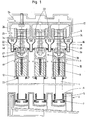
- the exemplary embodiment of a partition wall according to the invention shown in the figures comprises three sliding elements 1 which can be displaced in the horizontal direction in adjacent vertical planes and in particular can be formed by glass panes.
- the sliding elements 1 are guided in a guide profile 2, which is fixed to a fastening structure which is not to be explained in more detail here.
- lower edge profiles 5 are provided, each of which has a U-shaped section which surrounds the lower edge of the sliding element 1, the edge profile 5 extending over the entire length of the sliding element 1.
- silicone 6 is introduced into the joint between the U-shaped section of the edge profile 5 and the sliding element 1.
- Brushes 7, which extend over the length of the edge profile 5, are attached to the edge profile 5 on both sides and bear against side walls of U-shaped sections of the guide profile 2, which accommodate the edge profiles.
- the sliding elements 1 are fastened to element holders 3 in the region of their upper longitudinal edges. These are designed as profile rails, which extend over the length of the upper longitudinal edge of the sliding element 1 and one down have open, cross-sectionally U-shaped section which receives the upper longitudinal edge of the sliding element 1.
- At least two recesses 8 are arranged over the length of the longitudinal edge, which initially extend from the longitudinal edge in a slot shape and subsequently have an enlarged, circular area.
- This circular area is penetrated by a holding part 9 (FIG. 1), into which a screw 10 is screwed, which penetrates a bore in a web 11 of the element holder 3 and is carried by this web 11.
- lugs 12 are arranged on the inside of the U-shaped section of the element holder 3 below the holding part 9, which prevent pulling downwards of the holding part 9 from the U-shaped section of the element holder 3.
- silicone 13 is introduced on both sides between the element holder 3 and the sliding element 1, whereby a holding force is also applied in addition to achieving a seal.
- the element holders 3 are suspended from carriages 25, at least two horizontally spaced carriages 25 being provided for each sliding element 1. Rollers 26 are rotatably mounted on a respective carriage 25 and can be moved along an essentially horizontal track 23 of a carrier profile 24.
- the carrier profile 24 is fixed to a fastening structure which will not be described in more detail here.
- the raceway 23 is formed by the at least approximately horizontally lying upper sides of two webs of the carrier profile 4, between which there is an opening for the threaded bolt 16 to pass through, the end faces of the webs facing the opening forming vertical raceways 34.
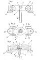
- a respective carriage 25 has two pairs of rollers 26 rolling along the essentially horizontal track 23, each pair of rollers 26 being connected to one another via an axis 27 (cf. FIGS. 2 to 5).
- the axis 27 passes through a bore 28 through the carriage 25 with play.
- This bore 28 has sections on both sides towards the outside of the carriage 25 which enlarge with respect to the vertical dimension of the bore 28.
- the bore 28 can be designed in the form of an elongated hole in these sections, the longitudinal axis of the elongated hole being vertical and the length of the elongated hole increases towards the outside of the carriage 25. Between these two sections, a central section with a constant diameter can be provided, through which the axis 27 passes with a certain clearance. Starting from its central position shown in FIG.
- the axis 27 can be pivoted about a horizontal pivot axis lying parallel to the raceway 23 in an angular range 29 with respect to the carriage 25, this angular range 29 starting from the central position being at least 1 ° on both sides.
- the axis 27 On both sides of the carriage, the axis 27 has an annular collar 30 which projects upwards and downwards over the extension of the bore 28 and on which a respective roller 26 is rotatably supported by means of a ball bearing 31 shown schematically in FIG.
- the distance between the collar 30 and the outside of the carriage 25 is smaller than that of the impeller 26.
- the collar 30 projects in the direction of the carriage 25 via the roller 26.
- the carriage 25 could also be provided with an outward projection in the area opposite the annular collar 30. In this way, when the axis 27 is pivoted, contact of the roller 26 on the carriage 25 is prevented and the pivoting of the axis 27 is limited.
- the two pairs of rollers 26 are arranged on both sides of a bore 32 which receives a threaded bolt 16 in the carriage.
- a guide roller 33 rotatably mounted about a vertical axis is rotatably mounted on the carriage 25. These guide rollers 33 serve for transverse guidance and for absorbing transverse forces and interact with the essentially vertical raceways 34 provided on the carrier profiles.
- a threaded bolt 16 is provided for suspending an element holder 3 from a respective carriage 25.
- a recess 35 extending from the top is introduced into the carriage 25, to which a bore 32 penetrating the carriage 25 is connected.
- the shaft 32 of the bolt 16 passes through the bore 32.
- two disks 36, 37 are arranged, which are provided on their abutting sides with sections of opposing spherical surfaces.
- the head 17 of the bolt 16 is thus carried by the carriage 25 with the interposition of the disks 36, 37, the shaft of the bolt 16 being pivotable on all sides within an angular range 38, which is preferably at least 1 °.
- the interacting sections of spherical surfaces being able to be arranged on the one hand on the disk, on the other hand on the bottom of the recess 35 or on the underside of the head 17.
- the interacting sections of spherical surfaces could also be provided on the bottom 35 and on the underside of the head 17 without the interposition of a disk.
- the shaft of the threaded bolt 16 protrudes at a distance from the carriage 25 through a hole in a supporting web 14 of the element holder 3.
- a nut 18 screwed onto the external thread of the threaded bolt 16, which carries the element holder 3, between the nut 18 and the support web 14, an intermediate plate 21 is arranged, which is preferably designed as a steel plate, in particular made of stainless steel.
- the weight of the sliding element 1 is transferred to the nut 18 via this intermediate plate 21 and subsequently to the carriage 25 via the threaded bolt 16.
- the element holder 3 is preferably designed as an extruded aluminum profile.
- the nut 18 is secured against rotation relative to the element holder 3 by a contact section 15 of the element holder.
- the lock nut 20 is loosened, i. H. spaced from the supporting web 14.
- the threaded bolt 16 can be rotated by means of a wrench attached to the adjusting nut 19, the element holder 3 being raised or lowered.
- adjusting nut 19 instead of the adjusting nut 19, another tool approach for rotating the threaded bolt 16 would in principle also be conceivable and possible, for example an attachment of opposite flats to the shaft of the threaded bolt 16 or a hole for inserting a pin.
- adjusting nut is preferred in order not to weaken the threaded bolt. This must be able to absorb considerable transverse forces, for example caused by wind forces.
- An inverted arrangement of the threaded bolt 16 would also be conceivable and possible, the head 17 being located below the supporting web 14 (with the intermediate plate 21 being interposed) so that the element holder 3 is carried by the head 17 of the threaded bolt 16.
- a nut screwed onto the free end of the shaft of the threaded bolt 16 (corresponding to the nut 18 in FIG. 1) is then carried by the carriage 25 by lying on the carriage or on one or more intermediate disks 36, 37. In this case, the carriage 25 would be provided with an abutment section preventing the nut from rotating.
- This contact section could, however, have a certain play with respect to the flattened side surfaces of the nut, so that although the nut is prevented from rotating, pivoting of the threaded bolt 16 within a certain angular range 38 relative to the carriage 25 is nevertheless possible.
- the threaded bolt could in principle be rotated by means of a rotary tool that can be inserted through a window in the element holder 3 and engages the head 17 of the threaded bolt.
- a cover profile 39 can be fastened to the carrier profile 24, for example by clipping it on (ie via a snap connection), it being possible to provide an additional screw lock.
- a sealing part 40 is arranged between the cover profile 39 and the element holder 3 extending over the length of the sliding element 1, for example in the form of a brush.
- the partition is sealed in the closed state.
- a seal could also be omitted.
- the sliding elements 1 could also end above the guide profile 2, wherein on the edge profile 5 downwardly extending, about a vertical axis rotatable guide rollers are provided, which are guided on both sides of the vertical raceways of the guide profile 2, around the side guide of the lower ends of the To achieve sliding elements 1.
- the sliding elements of a partition according to the invention can be large and heavy.
- the weight of the sliding elements can be more than 100 kg per sliding element.
- a partition according to the invention can also have two or more than three plate-shaped sliding elements. These sliding elements can consist, for example, of glass, metal or wood.
Landscapes
- Engineering & Computer Science (AREA)
- Mechanical Engineering (AREA)
- Support Devices For Sliding Doors (AREA)
Applications Claiming Priority (2)
| Application Number | Priority Date | Filing Date | Title |
|---|---|---|---|
| AT14582002 | 2002-09-27 | ||
| AT14582002 | 2002-09-27 |
Publications (1)
| Publication Number | Publication Date |
|---|---|
| EP1403459A2 true EP1403459A2 (fr) | 2004-03-31 |
Family
ID=31953366
Family Applications (1)
| Application Number | Title | Priority Date | Filing Date |
|---|---|---|---|
| EP20030021072 Withdrawn EP1403459A2 (fr) | 2002-09-27 | 2003-09-18 | Paroi de séparation avec éléments coulissant horizontalement |
Country Status (1)
| Country | Link |
|---|---|
| EP (1) | EP1403459A2 (fr) |
Cited By (7)
| Publication number | Priority date | Publication date | Assignee | Title |
|---|---|---|---|---|
| WO2009021627A1 (fr) * | 2007-08-16 | 2009-02-19 | Dorma Gmbh + Co. Kg | Chariot et système de suspension utilisant des chariots |
| WO2010019692A1 (fr) * | 2008-08-14 | 2010-02-18 | Hettich-Heinze Gmbh & Co. Kg | Chariot pour une porte |
| BE1020695A3 (nl) * | 2012-05-21 | 2014-03-04 | Louage En Wisselinck Nv | Looprolsysteem voor een schuifdeur en schuifdeursysteem omvattende een dergelijk looprolsysteem. |
| EP2476842A3 (fr) * | 2011-01-14 | 2015-03-18 | Dorma GmbH + Co. KG | Installation de portes coulissantes |
| EP3034741A1 (fr) * | 2014-12-15 | 2016-06-22 | DORMA Deutschland GmbH | Système de paroi coulissante doté d'un comportement acoustique amélioré |
| EP3034742A1 (fr) * | 2014-12-15 | 2016-06-22 | DORMA Deutschland GmbH | Système de paroi coulissante à couple de poussée très faible |
| KR20220100276A (ko) * | 2021-01-08 | 2022-07-15 | 주식회사 펜타포스 | 자동문 체결용 볼트어셈블리 및 볼트어셈블리와 결합된 도어상부구조물 |
Citations (2)
| Publication number | Priority date | Publication date | Assignee | Title |
|---|---|---|---|---|
| AT364128B (de) | 1980-03-18 | 1981-09-25 | Brachmann Nagel Erich Dkfm Dr | Verschiebbare trennwand |
| AT379184B (de) | 1984-01-17 | 1985-11-25 | Meusburger Walter | Trennwand mit horizontal verschiebbaren scheiben |
-
2003
- 2003-09-18 EP EP20030021072 patent/EP1403459A2/fr not_active Withdrawn
Patent Citations (2)
| Publication number | Priority date | Publication date | Assignee | Title |
|---|---|---|---|---|
| AT364128B (de) | 1980-03-18 | 1981-09-25 | Brachmann Nagel Erich Dkfm Dr | Verschiebbare trennwand |
| AT379184B (de) | 1984-01-17 | 1985-11-25 | Meusburger Walter | Trennwand mit horizontal verschiebbaren scheiben |
Cited By (12)
| Publication number | Priority date | Publication date | Assignee | Title |
|---|---|---|---|---|
| WO2009021627A1 (fr) * | 2007-08-16 | 2009-02-19 | Dorma Gmbh + Co. Kg | Chariot et système de suspension utilisant des chariots |
| US20100139037A1 (en) * | 2007-08-16 | 2010-06-10 | Dorma Gmbh + Co. Kg | Carriage and Suspension System Utilizing Carriages |
| CN101784740B (zh) * | 2007-08-16 | 2014-03-05 | 多玛两合有限公司 | 滑车和利用滑车的悬挂系统 |
| US8857015B2 (en) * | 2007-08-16 | 2014-10-14 | Dorma Gmbh + Co. Kg | Carriage and suspension system utilizing carriages |
| WO2010019692A1 (fr) * | 2008-08-14 | 2010-02-18 | Hettich-Heinze Gmbh & Co. Kg | Chariot pour une porte |
| US8046872B2 (en) | 2008-08-14 | 2011-11-01 | Hettich-Heinze Gmbh & Co. Kg | Carriage for a door |
| AU2009281967B2 (en) * | 2008-08-14 | 2015-03-26 | Hettich-Heinze Gmbh & Co. Kg | Carriage for a door |
| EP2476842A3 (fr) * | 2011-01-14 | 2015-03-18 | Dorma GmbH + Co. KG | Installation de portes coulissantes |
| BE1020695A3 (nl) * | 2012-05-21 | 2014-03-04 | Louage En Wisselinck Nv | Looprolsysteem voor een schuifdeur en schuifdeursysteem omvattende een dergelijk looprolsysteem. |
| EP3034741A1 (fr) * | 2014-12-15 | 2016-06-22 | DORMA Deutschland GmbH | Système de paroi coulissante doté d'un comportement acoustique amélioré |
| EP3034742A1 (fr) * | 2014-12-15 | 2016-06-22 | DORMA Deutschland GmbH | Système de paroi coulissante à couple de poussée très faible |
| KR20220100276A (ko) * | 2021-01-08 | 2022-07-15 | 주식회사 펜타포스 | 자동문 체결용 볼트어셈블리 및 볼트어셈블리와 결합된 도어상부구조물 |
Similar Documents
| Publication | Publication Date | Title |
|---|---|---|
| DE1584189B1 (de) | Kombinierter Schwenk- und Schiebetuermechanismus | |
| DE4133720C2 (de) | Feststell- und Verriegelungseinheit | |
| DE60304219T2 (de) | Vorrichtung zum herstellen einer verschiebbaren wandkonstruktion | |
| EP0235658A1 (fr) | Cloison, notamment pour douche d'angle | |
| DE102009044383A1 (de) | Morphologisches Modulsystem zur Erstellung von unterschiedlichen Gebäudeverschlüssen | |
| EP2159345B1 (fr) | Fixation pour éléments de revêtement | |
| EP0705954A1 (fr) | Aile coulissante pour la fermeture suivant les besoins d'une façade ouverte d'un balcon, jardin d'hiver et similaires | |
| CH665677A5 (de) | Trennwand mit horizontal verschiebbaren scheiben. | |
| EP1403459A2 (fr) | Paroi de séparation avec éléments coulissant horizontalement | |
| EP1427907B1 (fr) | Systeme de cloison coulissante avec un element de battant de porte coulissant et pivotant | |
| DE3602440C2 (fr) | ||
| EP1496182A2 (fr) | Système de portes coulissantes avec une pluralité de panneaux coulissants | |
| EP2058456B1 (fr) | Toit | |
| EP3290612B1 (fr) | Dispositif formant toit et procédé de fabrication d'un dispositif formant toit | |
| DE19539014A1 (de) | Schiebetürbeschlag | |
| EP0679788B1 (fr) | Chariot ainsi qu'ensemble coulissant et rail | |
| EP1039091B1 (fr) | Revêtement d'une surface de mur ou de toit | |
| EP1054126B1 (fr) | Chariot pour ferrure basculant-coulissant | |
| EP1338742B1 (fr) | Réglage de la hauteur de montage d'une porte coulissante se déplaçant sur un système roulant | |
| CH649341A5 (en) | Corner joint on a turn-and-tilt window or on a turn-and-tilt door | |
| EP1852567B1 (fr) | Chariot | |
| EP3816383A1 (fr) | Agencement de porte coulissante | |
| DE19835684A1 (de) | Verfahrbare Türflügelanordnung | |
| DE20120613U1 (de) | Scharnier | |
| AT527118B1 (de) | Säule zum Abstützen eines Daches |
Legal Events
| Date | Code | Title | Description |
|---|---|---|---|
| PUAI | Public reference made under article 153(3) epc to a published international application that has entered the european phase |
Free format text: ORIGINAL CODE: 0009012 |
|
| AK | Designated contracting states |
Kind code of ref document: A2 Designated state(s): AT BE BG CH CY CZ DE DK EE ES FI FR GB GR HU IE IT LI LU MC NL PT RO SE SI SK TR |
|
| AX | Request for extension of the european patent |
Extension state: AL LT LV MK |
|
| STAA | Information on the status of an ep patent application or granted ep patent |
Free format text: STATUS: THE APPLICATION IS DEEMED TO BE WITHDRAWN |
|
| 18D | Application deemed to be withdrawn |
Effective date: 20060531 |