EP1402829A2 - Wirbelkörperplatte für ein Wirbelsäulenbefestigungssystem - Google Patents
Wirbelkörperplatte für ein Wirbelsäulenbefestigungssystem Download PDFInfo
- Publication number
- EP1402829A2 EP1402829A2 EP03020809A EP03020809A EP1402829A2 EP 1402829 A2 EP1402829 A2 EP 1402829A2 EP 03020809 A EP03020809 A EP 03020809A EP 03020809 A EP03020809 A EP 03020809A EP 1402829 A2 EP1402829 A2 EP 1402829A2
- Authority
- EP
- European Patent Office
- Prior art keywords
- vertebra body
- vertebra
- diagonal line
- body plate
- vertebral column
- Prior art date
- Legal status (The legal status is an assumption and is not a legal conclusion. Google has not performed a legal analysis and makes no representation as to the accuracy of the status listed.)
- Withdrawn
Links
- 238000003780 insertion Methods 0.000 claims abstract description 8
- 230000037431 insertion Effects 0.000 claims abstract description 8
- 230000001154 acute effect Effects 0.000 claims abstract description 6
- QNRATNLHPGXHMA-XZHTYLCXSA-N (r)-(6-ethoxyquinolin-4-yl)-[(2s,4s,5r)-5-ethyl-1-azabicyclo[2.2.2]octan-2-yl]methanol;hydrochloride Chemical compound Cl.C([C@H]([C@H](C1)CC)C2)CN1[C@@H]2[C@H](O)C1=CC=NC2=CC=C(OCC)C=C21 QNRATNLHPGXHMA-XZHTYLCXSA-N 0.000 claims description 2
- 238000000034 method Methods 0.000 description 2
- PCTMTFRHKVHKIS-BMFZQQSSSA-N (1s,3r,4e,6e,8e,10e,12e,14e,16e,18s,19r,20r,21s,25r,27r,30r,31r,33s,35r,37s,38r)-3-[(2r,3s,4s,5s,6r)-4-amino-3,5-dihydroxy-6-methyloxan-2-yl]oxy-19,25,27,30,31,33,35,37-octahydroxy-18,20,21-trimethyl-23-oxo-22,39-dioxabicyclo[33.3.1]nonatriaconta-4,6,8,10 Chemical compound C1C=C2C[C@@H](OS(O)(=O)=O)CC[C@]2(C)[C@@H]2[C@@H]1[C@@H]1CC[C@H]([C@H](C)CCCC(C)C)[C@@]1(C)CC2.O[C@H]1[C@@H](N)[C@H](O)[C@@H](C)O[C@H]1O[C@H]1/C=C/C=C/C=C/C=C/C=C/C=C/C=C/[C@H](C)[C@@H](O)[C@@H](C)[C@H](C)OC(=O)C[C@H](O)C[C@H](O)CC[C@@H](O)[C@H](O)C[C@H](O)C[C@](O)(C[C@H](O)[C@H]2C(O)=O)O[C@H]2C1 PCTMTFRHKVHKIS-BMFZQQSSSA-N 0.000 description 1
- 238000005452 bending Methods 0.000 description 1
- 230000002093 peripheral effect Effects 0.000 description 1
Images


Classifications
-
- A—HUMAN NECESSITIES
- A61—MEDICAL OR VETERINARY SCIENCE; HYGIENE
- A61B—DIAGNOSIS; SURGERY; IDENTIFICATION
- A61B17/00—Surgical instruments, devices or methods
- A61B17/56—Surgical instruments or methods for treatment of bones or joints; Devices specially adapted therefor
- A61B17/58—Surgical instruments or methods for treatment of bones or joints; Devices specially adapted therefor for osteosynthesis, e.g. bone plates, screws or setting implements
- A61B17/68—Internal fixation devices, including fasteners and spinal fixators, even if a part thereof projects from the skin
- A61B17/70—Spinal positioners or stabilisers, e.g. stabilisers comprising fluid filler in an implant
- A61B17/7059—Cortical plates
Definitions
- the present invention relates to a vertebra body plate for a vertebral column fixing system, and more particularly to a vertebra body plate which can be easily placed in a vertebra body.
- the fixing method according to the related art is comprised of a plurality of spikes inserted into the vertebral column, a pair of square connection devices provided with engagement holes engaging with bolts screwed into the vertebral column and a connection member for connecting the connection devices.
- connection devices since a rigidity of the connection devices is great, there is a problem that it is hard to place the connection device along a shape of the vertebra body of the vertebral column having a curvature. Further, there is a problem that a contact area between the connection device and the vertebra body is small.
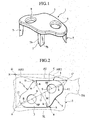
- a content of the present invention is a rhombic vertebra body plate for a vertebral column fixing system comprising: a main body portion having an approximately point symmetric shape around a point in which a first diagonal line connecting a pair of acute angle portions having acute angles opposing to each other, crosses a second diagonal line connecting a pair of obtuse angle portions having obtuse angles opposing to each other; at least one screw insertion hole provided on or near the first diagonal line of the main body portion or on or near the second diagonal line; and at least one spike provided on each of the first diagonal line and the second diagonal line.
- a vertebra body plate 1 is comprised of a plate main body 3 (a main body portion) made of a material which can be slightly plastically deformed by a great external force, a plurality of spikes 7 provided on the plate main body 3 and stuck into a vertebra body 5 of a vertebral column (refer to Fig. 2), and a plurality of screw insertion holes 9 through which screws (not shown) screwed into the vertebra body 5 are inserted.
- the spike 7 is in the form of an approximately V-shaped in cross section, and is comprised of a pair of surfaces 7a and 7b opposing to each other. A distal end portion of the spike 7 is tapered and is structured such as to easily stick into the vertebra body.
- a shape of the plate main body 3 is formed by the following steps. Firstly, as shown in Fig. 2, when pressing corner portions C and D in a virtual quadrangle ABCD in which four corner portions form 90 degrees in a direction of an arrow X, the corner portions C and D are moved along arrows AR1 and AR2 , and a rhomboid ABC' D' is formed. In the rhomboid ABC'D', the corner portions A and C' oppose to each other and form an acute angle, and the corner portions B and D' oppose to each other and form an obtuse angle .
- a line AB and a line C'D' form linear edge portions approximately in parallel to upper and lower end plates 5U and 5L in the vertebra body 5, and a line AD' and a line BC ' are inclined with respect to the end plates 5U and 5L . Further, the corner portion C' is positioned in a protruding side (a protruding edge portion) relatively protruding with respect to the line AB.
- centers 9P of the screw insertion holes 9 , 9 are provided in symmetrical positions on the line M around the intersection point O. Further, a pair of spikes 7 are provided in symmetrical positions outside the screw insertion holes 9 (refer to Fig. 4). In other words, a distance from the center O to one center 9P (spike 7) is equal to a distance from the center O to another center 9P (spike 7).
- a pair of spikes 7 may be arranged on the line M, or may be slightly displaced from the line M within an allowable range. Further, a pair of spikes 7 are provided in the symmetrical positions on the line N around the intersection point O or the symmetrical position near the line N.
- the corner portions A, B, C' and D' of the plate main body 3 have a curvature R.
- This curvature R is appropriately determined on the basis of the distance from the center 9P of the screw insertion hole 9 to the line AB and the line C' D' and the like.
- a part of the lines BC' and AD' has a curvature S, and is smoothly connected to the portion of the curvature R.
- This curvature S is also appropriately determined on the basis of the curvature R and the like.
- the line D'C' is smoothly connected to the portion having the curvature S from the protruding portion 11 having the curvature R, and is thereafter smoothly connected again to the line AB by the curvature R.
- the plate main body 3 is structured, as shown in Fig. 2, such that the upper and lower lines AB and C'D' of the plate main body 3 are approximately in parallel to the upper and lower end plates 5U and 5L of the vertebra body 5, and the corner portion C' corresponding to a pedicle arch vertebra 5A of the vertebra has a shape provided with the protruding portion 11 protruding to a side of the pedicle of arch of the vertebra 5A and an approximately point symmetrical shape around the intersection point O.
- the plate main body 3 is formed in a slightly curved manner so as to correspond to a peripheral surface of the vertebra body 5. In this case, the structure of the plate 3 may be obtained by deforming the point symmetrical shape within the allowable range.
- Figs. 5A and 5B show a vertebra body plate 1A having a symmetrical shape with the vertebra body plate 1.
- a shape thereof is symmetrical with that of the first embodiment, and the other structures are the same as those of the first embodiment mentioned above. Accordingly, the same reference numerals are attached to the constituting portions achieving the same functions, and a detailed description thereof will be omitted.
- the vertebra body plate 1A is used for a vertebral column fixing system in which a plurality of screws (not shown) are screwed into the separated vertebra bodies 5 in the vertebral column, and a portion near an end portion of a rod for connecting the vertebra body is supported and fixed by a rod formed in a head portion of the screw.
- the vertebra body plate 1A is fixed to the vertebra body 5 before the screw is screwed into the vertebra body 5.
- the vertebra body plate 1A is selected in correspondence to the shape of the individual vertebra body. Further, when placing the vertebra body plate 1 (1A) in the vertebra body 5, the shape of the vertebra body plate 1 is deformed so as to approximately correspond to the surface shape of the vertebra body to be placed.
- the vertebra body plate 1 (1A) can be deformed in its shape in correspondence to the curvature of the vertebra body by bending the protruding portions 11, 11 around the center O, and a contact area between the vertebra body plate 1 (1A) and the vertebra body is larger than the conventional one.
- the contact area is large in the case that a plurality of spikes 7 provided in the vertebra body plate 1 (1A) are stuck to the vertebra body 5 so as to be fixed, it is possible to more securely fix the vertebra body plate 1 (1A) to the vertebra body 5.
- the screw (not shown) is screwed into each of the vertebra bodies 5 through the screw insertion hole 9 provided in each of the vertebra body plate 1 (1A), and the portion near the end portion of the rod for connecting the vertebra body is supported and fixed by the rod engagement portion provided in the head portion of the screw, whereby the separated vertebra bodies 5 are connected, and the vertebral column can be fixed.
Landscapes
- Health & Medical Sciences (AREA)
- Orthopedic Medicine & Surgery (AREA)
- Life Sciences & Earth Sciences (AREA)
- Neurology (AREA)
- Surgery (AREA)
- Heart & Thoracic Surgery (AREA)
- Engineering & Computer Science (AREA)
- Biomedical Technology (AREA)
- Nuclear Medicine, Radiotherapy & Molecular Imaging (AREA)
- Medical Informatics (AREA)
- Molecular Biology (AREA)
- Animal Behavior & Ethology (AREA)
- General Health & Medical Sciences (AREA)
- Public Health (AREA)
- Veterinary Medicine (AREA)
- Prostheses (AREA)
- Surgical Instruments (AREA)
Applications Claiming Priority (2)
| Application Number | Priority Date | Filing Date | Title |
|---|---|---|---|
| JP2002267300A JP2004097707A (ja) | 2002-09-12 | 2002-09-12 | 脊柱固定システム用の椎体プレート |
| JP2002267300 | 2002-09-12 |
Publications (2)
| Publication Number | Publication Date |
|---|---|
| EP1402829A2 true EP1402829A2 (de) | 2004-03-31 |
| EP1402829A3 EP1402829A3 (de) | 2006-06-14 |
Family
ID=31973194
Family Applications (1)
| Application Number | Title | Priority Date | Filing Date |
|---|---|---|---|
| EP03020809A Withdrawn EP1402829A3 (de) | 2002-09-12 | 2003-09-12 | Wirbelkörperplatte für ein Wirbelsäulenbefestigungssystem |
Country Status (4)
| Country | Link |
|---|---|
| US (1) | US20040127902A1 (de) |
| EP (1) | EP1402829A3 (de) |
| JP (1) | JP2004097707A (de) |
| KR (1) | KR100562387B1 (de) |
Cited By (3)
| Publication number | Priority date | Publication date | Assignee | Title |
|---|---|---|---|---|
| WO2006113353A3 (en) * | 2005-04-19 | 2006-12-21 | Warsaw Orthopedic Inc | Antero- lateral plating systems and methods for spinal stabilization |
| EP1781196A4 (de) * | 2004-08-27 | 2009-04-29 | Depuy Spine Inc | Wirbelklammern und einführinstrumente |
| EP2135562A1 (de) * | 2008-06-20 | 2009-12-23 | Arthrex, Inc. | Keilprofilplatte |
Families Citing this family (32)
| Publication number | Priority date | Publication date | Assignee | Title |
|---|---|---|---|---|
| US8100976B2 (en) * | 2003-04-21 | 2012-01-24 | Rsb Spine Llc | Implant subsidence control |
| US8613772B2 (en) * | 2003-04-21 | 2013-12-24 | Rsb Spine Llc | Lateral mount implant device |
| US20170020683A1 (en) | 2003-04-21 | 2017-01-26 | Rsb Spine Llc | Bone plate stabilization system and method for its use |
| US9278009B2 (en) * | 2003-04-21 | 2016-03-08 | Rsb Spine Llc | Spine implants |
| US7985255B2 (en) * | 2003-04-21 | 2011-07-26 | Rsb Spine Llc | Implant subsidence control |
| US7306605B2 (en) * | 2003-10-02 | 2007-12-11 | Zimmer Spine, Inc. | Anterior cervical plate |
| US7931680B2 (en) * | 2005-03-31 | 2011-04-26 | Depuy Products, Inc. | Plate for lengthening the lateral column of the foot |
| US8414616B2 (en) * | 2006-09-12 | 2013-04-09 | Pioneer Surgical Technology, Inc. | Mounting devices for fixation devices and insertion instruments used therewith |
| US9039768B2 (en) | 2006-12-22 | 2015-05-26 | Medos International Sarl | Composite vertebral spacers and instrument |
| US7922767B2 (en) * | 2007-07-07 | 2011-04-12 | Jmea Corporation | Disk fusion implant |
| FR2926453B1 (fr) | 2008-01-17 | 2011-03-18 | Warsaw Orthopedic Inc | Dispositif d'osteosynthese rachidienne |
| US20090248092A1 (en) | 2008-03-26 | 2009-10-01 | Jonathan Bellas | Posterior Intervertebral Disc Inserter and Expansion Techniques |
| US20100094358A1 (en) * | 2008-10-10 | 2010-04-15 | K2M, Inc. | Spinal staple |
| US9301785B2 (en) * | 2008-10-21 | 2016-04-05 | K2M, Inc. | Spinal buttress plate |
| US9526620B2 (en) | 2009-03-30 | 2016-12-27 | DePuy Synthes Products, Inc. | Zero profile spinal fusion cage |
| US9393129B2 (en) | 2009-12-10 | 2016-07-19 | DePuy Synthes Products, Inc. | Bellows-like expandable interbody fusion cage |
| US11529241B2 (en) | 2010-09-23 | 2022-12-20 | DePuy Synthes Products, Inc. | Fusion cage with in-line single piece fixation |
| US20120078373A1 (en) | 2010-09-23 | 2012-03-29 | Thomas Gamache | Stand alone intervertebral fusion device |
| US20120078372A1 (en) | 2010-09-23 | 2012-03-29 | Thomas Gamache | Novel implant inserter having a laterally-extending dovetail engagement feature |
| US9248028B2 (en) | 2011-09-16 | 2016-02-02 | DePuy Synthes Products, Inc. | Removable, bone-securing cover plate for intervertebral fusion cage |
| US9271836B2 (en) | 2012-03-06 | 2016-03-01 | DePuy Synthes Products, Inc. | Nubbed plate |
| US10182921B2 (en) | 2012-11-09 | 2019-01-22 | DePuy Synthes Products, Inc. | Interbody device with opening to allow packing graft and other biologics |
| US9566120B2 (en) | 2013-01-16 | 2017-02-14 | Stryker Corporation | Navigation systems and methods for indicating and reducing line-of-sight errors |
| US9993273B2 (en) | 2013-01-16 | 2018-06-12 | Mako Surgical Corp. | Bone plate and tracking device using a bone plate for attaching to a patient's anatomy |
| USD728104S1 (en) * | 2013-08-09 | 2015-04-28 | Nextremity Solutions, Inc. | Bone compression staple |
| USD728103S1 (en) * | 2013-08-09 | 2015-04-28 | Nextremity Solutions, Inc. | Bone fusion implant |
| WO2016033426A1 (en) | 2014-08-28 | 2016-03-03 | Nextremity Solutions, Inc. | Bone fixation devices and methods |
| US9901457B2 (en) | 2014-10-16 | 2018-02-27 | Jmea Corporation | Coiling implantable prostheses |
| USD840035S1 (en) * | 2015-01-07 | 2019-02-05 | Nextremity Solutions, Inc. | Bone fixation implant |
| US10537395B2 (en) | 2016-05-26 | 2020-01-21 | MAKO Surgical Group | Navigation tracker with kinematic connector assembly |
| US10940016B2 (en) | 2017-07-05 | 2021-03-09 | Medos International Sarl | Expandable intervertebral fusion cage |
| US12059804B2 (en) | 2019-05-22 | 2024-08-13 | Mako Surgical Corp. | Bidirectional kinematic mount |
Family Cites Families (19)
| Publication number | Priority date | Publication date | Assignee | Title |
|---|---|---|---|---|
| JPH066810Y2 (ja) * | 1989-11-29 | 1994-02-23 | 旭光学工業株式会社 | 椎体固定用プレート |
| JPH07163580A (ja) * | 1993-12-15 | 1995-06-27 | Mizuho Ika Kogyo Kk | 側弯症前方矯正装置 |
| US5662652A (en) * | 1994-04-28 | 1997-09-02 | Schafer Micomed Gmbh | Bone surgery holding apparatus |
| US5620443A (en) * | 1995-01-25 | 1997-04-15 | Danek Medical, Inc. | Anterior screw-rod connector |
| DE29501880U1 (de) * | 1995-02-06 | 1995-05-24 | Karl Leibinger Medizintechnik GmbH & Co. KG, 78570 Mühlheim | Vorrichtung zur Knochenverlängerung |
| US6780186B2 (en) * | 1995-04-13 | 2004-08-24 | Third Millennium Engineering Llc | Anterior cervical plate having polyaxial locking screws and sliding coupling elements |
| JP3571238B2 (ja) * | 1998-10-31 | 2004-09-29 | 日本特殊陶業株式会社 | 骨弁固定具 |
| JP3289140B2 (ja) * | 1999-06-17 | 2002-06-04 | 独立行政法人産業技術総合研究所 | 高生体親和性インプラント及びその作製法 |
| WO2001003570A2 (en) * | 1999-07-07 | 2001-01-18 | Wall M D Eric J | Spinal correction system |
| US6231610B1 (en) * | 1999-08-25 | 2001-05-15 | Allegiance Corporation | Anterior cervical column support device |
| DE19950252C2 (de) * | 1999-10-18 | 2002-01-17 | Schaefer Micomed Gmbh | Knochenplatte |
| DE19950270C2 (de) * | 1999-10-18 | 2003-07-17 | Bernd Schaefer | Knochenplatte |
| WO2001062136A2 (en) * | 2000-02-24 | 2001-08-30 | Stryker Instruments | Bioabsorbable plates, fasteners, tools and method of using same |
| US6514274B1 (en) * | 2000-02-25 | 2003-02-04 | Arthrotek, Inc. | Method and apparatus for rotator cuff repair |
| WO2002009590A1 (fr) * | 2000-07-27 | 2002-02-07 | Jms Co., Ltd. | Dispositif supportant un tissu pour traitement medical |
| US6524311B2 (en) * | 2000-12-01 | 2003-02-25 | Robert W. Gaines, Jr. | Method and apparatus for performing spinal procedures |
| DE20104634U1 (de) * | 2001-03-17 | 2001-06-13 | AlloCon GmbH, 42929 Wermelskirchen | Wirbelplatte |
| FR2836371A1 (fr) * | 2002-02-28 | 2003-08-29 | Eurosurgical | Connecteur pour dispositif d'ancrage vertebral par voie anterieure |
| US6682563B2 (en) * | 2002-03-04 | 2004-01-27 | Michael S. Scharf | Spinal fixation device |
-
2002
- 2002-09-12 JP JP2002267300A patent/JP2004097707A/ja active Pending
-
2003
- 2003-09-08 KR KR1020030062795A patent/KR100562387B1/ko not_active Expired - Fee Related
- 2003-09-11 US US10/659,303 patent/US20040127902A1/en not_active Abandoned
- 2003-09-12 EP EP03020809A patent/EP1402829A3/de not_active Withdrawn
Cited By (10)
| Publication number | Priority date | Publication date | Assignee | Title |
|---|---|---|---|---|
| EP1781196A4 (de) * | 2004-08-27 | 2009-04-29 | Depuy Spine Inc | Wirbelklammern und einführinstrumente |
| US7883510B2 (en) | 2004-08-27 | 2011-02-08 | Depuy Spine, Inc. | Vertebral staples and insertion tools |
| AU2005280615B2 (en) * | 2004-08-27 | 2011-05-12 | Depuy Spine, Inc. | Vertebral staples and insertion tools |
| US8623020B2 (en) | 2004-08-27 | 2014-01-07 | Depuy Spine, Inc. | Vertebral staples and insertion tools |
| WO2006113353A3 (en) * | 2005-04-19 | 2006-12-21 | Warsaw Orthopedic Inc | Antero- lateral plating systems and methods for spinal stabilization |
| US7678113B2 (en) | 2005-04-19 | 2010-03-16 | Warsaw Orthopedic, Inc. | Antero-lateral plating systems and methods for spinal stabilization |
| US8109980B2 (en) | 2005-04-19 | 2012-02-07 | Kyphon Sarl | Antero-lateral plating systems and methods for spinal stabilization |
| US8470007B2 (en) | 2005-04-19 | 2013-06-25 | Warsaw Orthopedic, Inc. | Antero-lateral plating systems and methods for spinal stabilization |
| EP2135562A1 (de) * | 2008-06-20 | 2009-12-23 | Arthrex, Inc. | Keilprofilplatte |
| US8728131B2 (en) | 2008-06-20 | 2014-05-20 | Arthrex, Inc. | Wedged Profile Plate |
Also Published As
| Publication number | Publication date |
|---|---|
| EP1402829A3 (de) | 2006-06-14 |
| KR100562387B1 (ko) | 2006-03-17 |
| JP2004097707A (ja) | 2004-04-02 |
| US20040127902A1 (en) | 2004-07-01 |
| KR20040024494A (ko) | 2004-03-20 |
Similar Documents
| Publication | Publication Date | Title |
|---|---|---|
| EP1402829A2 (de) | Wirbelkörperplatte für ein Wirbelsäulenbefestigungssystem | |
| US7530991B2 (en) | Vertebral body distance retainer | |
| US6958065B2 (en) | Rod for cervical vertebra and connecting system thereof | |
| US7135043B2 (en) | Intervertebral cage | |
| US5658284A (en) | Connection member for the connection of a resilient rod with a bone screw which can be anchored in a vertebra | |
| US5976141A (en) | Threaded insert for bone plate screw hole | |
| KR100282786B1 (ko) | 뼈고정판 | |
| CA1227613A (en) | Six finger wood jointing connector | |
| US6432109B1 (en) | Connection device for osteosynthesis | |
| JP2005515824A5 (de) | ||
| US4764803A (en) | Thin semiconductor card | |
| US6049459A (en) | Nesting clamps for electrical components | |
| US20110060372A1 (en) | Bone fixing device | |
| US20130079824A1 (en) | Frictional screw-rod connection having an indirect form-locking portion | |
| US20170030389A1 (en) | Clamping Snap-In Fastener | |
| US6554835B1 (en) | Skull fixation device | |
| WO2001056452A3 (en) | Volar fixation system | |
| EP1642630A1 (de) | Konstruktionsstein | |
| US5646442A (en) | Contact structure for IC socket | |
| USD492895S1 (en) | Captive screw | |
| KR101148542B1 (ko) | 플립 칩 구성을 갖는 전기 소자 | |
| KR100281434B1 (ko) | 초음파 혼의 캐필러리 유지구조 | |
| JP2741585B2 (ja) | 骨固定装置 | |
| JP3248124B2 (ja) | 橋梁用伸縮継手 | |
| JP3956968B2 (ja) | トラス部材のプレート継手構造 |
Legal Events
| Date | Code | Title | Description |
|---|---|---|---|
| PUAI | Public reference made under article 153(3) epc to a published international application that has entered the european phase |
Free format text: ORIGINAL CODE: 0009012 |
|
| 17P | Request for examination filed |
Effective date: 20030912 |
|
| AK | Designated contracting states |
Kind code of ref document: A2 Designated state(s): AT BE BG CH CY CZ DE DK EE ES FI FR GB GR HU IE IT LI LU MC NL PT RO SE SI SK TR |
|
| AX | Request for extension of the european patent |
Extension state: AL LT LV MK |
|
| RIN1 | Information on inventor provided before grant (corrected) |
Inventor name: TAKAMIDO, HIROSHI C/O SHOWA IKA KOHGYO CO.LTD. Inventor name: ORIBE, KAZUYA C/O SHOWA IKA KOHGYO CO.LTD. Inventor name: HASEGAWA, KAZUHIRO Inventor name: UEYAMA, KAZUMASA Inventor name: SATO, SHIGENOBU Inventor name: NAKAHARA, SHINNOSUKE Inventor name: NOHARA, YUTAKA Inventor name: SUZUKI, NOBUMASA |
|
| PUAL | Search report despatched |
Free format text: ORIGINAL CODE: 0009013 |
|
| AK | Designated contracting states |
Kind code of ref document: A3 Designated state(s): AT BE BG CH CY CZ DE DK EE ES FI FR GB GR HU IE IT LI LU MC NL PT RO SE SI SK TR |
|
| AX | Request for extension of the european patent |
Extension state: AL LT LV MK |
|
| AKX | Designation fees paid |
Designated state(s): DE FR |
|
| 17Q | First examination report despatched |
Effective date: 20090119 |
|
| STAA | Information on the status of an ep patent application or granted ep patent |
Free format text: STATUS: THE APPLICATION IS DEEMED TO BE WITHDRAWN |
|
| 18D | Application deemed to be withdrawn |
Effective date: 20110401 |