EP1402686B1 - Drahtloses kommunikationssystem - Google Patents
Drahtloses kommunikationssystem Download PDFInfo
- Publication number
- EP1402686B1 EP1402686B1 EP02735806A EP02735806A EP1402686B1 EP 1402686 B1 EP1402686 B1 EP 1402686B1 EP 02735806 A EP02735806 A EP 02735806A EP 02735806 A EP02735806 A EP 02735806A EP 1402686 B1 EP1402686 B1 EP 1402686B1
- Authority
- EP
- European Patent Office
- Prior art keywords
- guest
- host
- declaration
- signal
- area
- Prior art date
- Legal status (The legal status is an assumption and is not a legal conclusion. Google has not performed a legal analysis and makes no representation as to the accuracy of the status listed.)
- Expired - Lifetime
Links
- 230000005540 biological transmission Effects 0.000 claims abstract description 35
- 238000000034 method Methods 0.000 claims description 24
- 230000009471 action Effects 0.000 claims description 13
- 230000004044 response Effects 0.000 claims description 4
- 230000008569 process Effects 0.000 description 13
- 230000008901 benefit Effects 0.000 description 3
- 230000004069 differentiation Effects 0.000 description 1
- 230000001960 triggered effect Effects 0.000 description 1
Images


Classifications
-
- H—ELECTRICITY
- H04—ELECTRIC COMMUNICATION TECHNIQUE
- H04W—WIRELESS COMMUNICATION NETWORKS
- H04W60/00—Affiliation to network, e.g. registration; Terminating affiliation with the network, e.g. de-registration
-
- H—ELECTRICITY
- H04—ELECTRIC COMMUNICATION TECHNIQUE
- H04M—TELEPHONIC COMMUNICATION
- H04M1/00—Substation equipment, e.g. for use by subscribers
- H04M1/72—Mobile telephones; Cordless telephones, i.e. devices for establishing wireless links to base stations without route selection
- H04M1/724—User interfaces specially adapted for cordless or mobile telephones
- H04M1/72403—User interfaces specially adapted for cordless or mobile telephones with means for local support of applications that increase the functionality
- H04M1/72409—User interfaces specially adapted for cordless or mobile telephones with means for local support of applications that increase the functionality by interfacing with external accessories
- H04M1/72412—User interfaces specially adapted for cordless or mobile telephones with means for local support of applications that increase the functionality by interfacing with external accessories using two-way short-range wireless interfaces
-
- H—ELECTRICITY
- H04—ELECTRIC COMMUNICATION TECHNIQUE
- H04M—TELEPHONIC COMMUNICATION
- H04M1/00—Substation equipment, e.g. for use by subscribers
- H04M1/72—Mobile telephones; Cordless telephones, i.e. devices for establishing wireless links to base stations without route selection
- H04M1/725—Cordless telephones
- H04M1/72502—Cordless telephones with one base station connected to a single line
- H04M1/72505—Radio link set-up procedures
- H04M1/72513—On hold, intercom or transfer communication modes
-
- H—ELECTRICITY
- H04—ELECTRIC COMMUNICATION TECHNIQUE
- H04W—WIRELESS COMMUNICATION NETWORKS
- H04W84/00—Network topologies
- H04W84/02—Hierarchically pre-organised networks, e.g. paging networks, cellular networks, WLAN [Wireless Local Area Network] or WLL [Wireless Local Loop]
- H04W84/10—Small scale networks; Flat hierarchical networks
- H04W84/16—WPBX [Wireless Private Branch Exchange]
-
- H—ELECTRICITY
- H04—ELECTRIC COMMUNICATION TECHNIQUE
- H04W—WIRELESS COMMUNICATION NETWORKS
- H04W4/00—Services specially adapted for wireless communication networks; Facilities therefor
- H04W4/02—Services making use of location information
-
- H—ELECTRICITY
- H04—ELECTRIC COMMUNICATION TECHNIQUE
- H04W—WIRELESS COMMUNICATION NETWORKS
- H04W48/00—Access restriction; Network selection; Access point selection
- H04W48/08—Access restriction or access information delivery, e.g. discovery data delivery
-
- H—ELECTRICITY
- H04—ELECTRIC COMMUNICATION TECHNIQUE
- H04W—WIRELESS COMMUNICATION NETWORKS
- H04W48/00—Access restriction; Network selection; Access point selection
- H04W48/16—Discovering, processing access restriction or access information
-
- H—ELECTRICITY
- H04—ELECTRIC COMMUNICATION TECHNIQUE
- H04W—WIRELESS COMMUNICATION NETWORKS
- H04W76/00—Connection management
- H04W76/10—Connection setup
Definitions
- the invention relates to a wireless communication system comprising at least one guest having means including a guest transmitter for transmitting guest signals and at least one host having means including a host receiver for receiving the guest signals, said host comprising means for establishing a link with the guest upon reception of a declaration signal transmitted by the guest, after which the host will respond to regular operation signals transmitted by the linked guest.
- the system further comprising means for establishing the link with the guest upon reception by the host of the declaration signal transmitted by the guest while the guest transmitter is located within a declaration area of the host, said declaration area being an area substantially different from a normal operating area of the guest/host pair, and said means not establishing the link with the guest upon transmission of the declaration signal by the guest while the guest transmitter is located outside said declaration area.
- Such a wireless communication system is known from PCT Patent application number WO94/10785 which describes a process for linking a base station (a host) with a mobile station (a guest) in the framework of the DECT standard (Digital Enhanced Cordless Telephone).
- a user has to perform a first selection consisting in selecting which host among the plurality of hosts of the system a guest is to be linked to.
- first selection which is often performed by pushing a particular button of the selected host
- the selected host transmits a announcement signal for the attention of the guests.
- second selection by selecting to which guest among the plurality of guests of the system the selected host is to be linked.
- second selection which is often performed by pushing a particular button (combination) of the selected guest, the selected guest transmits a response to the announcement signal in the form of a declaration signal for the attention of the selected host.
- This linking process is to make sure that a host does not respond to just any guest. Indeed, subsequent to the linking process, the selected host will respond to regular operation signals transmitted by the linked guests and will not respond to regular operation signals transmitted by non-linked guests.
- the wireless communication system in accordance with the invention is characterized in that the guest uses substantially the same transmission power for transmitting the declaration signal and for transmitting regular operation signals, said host being adapted to determine the origin of the declaration signal by measuring the signal strength of the received declaration signal, the declaration area being defined by a first threshold such that if the measured signal strength is greater than or equal to said first threshold, the measured signal is determined to be sent from within said declaration area.
- the user first brings the guest's guest transmitter into the declaration area of the host, said declaration area being different from the normal operating area of said host.
- the user thereby indirectly selects said host.
- the user then performs an action on the guest, for example, by pressing a particular button on said guest, thereby selecting said guest.
- the selected guest transmits a declaration signal for the attention of the hosts.
- the selected host Upon reception of this signal, the selected host establishes the link with the selected guest. If the selected guest transmits this signal from outside the host's declaration area, the host either does not accept this signal or does not detect this signal and consequently does not establish the link with the selected guest.
- the selection of the host, the selection of the guest, and the linking of the selected host with the selected guest can thus be performed simultaneously by a single user action, thereby simplifying the linking process.
- a system according to the invention does not require a direct user action on the host in order to select said host. This additional advantage may be used in cases where a direct action on the host is not desirable and/or not possible.
- the system according to the invention is such that the declaration area of the host extends around the host receiver and is substantially smaller than and is included in the normal operating area of the guest transmitter/host receiver pair.
- a single host receiver thus suffices for handling both declaration signals and regular operating signals, thereby simplifying the system.
- a radius of the declaration area of the host does not exceed 10% of the radius of the normal operating area of the guest transmitter/host receiver pair, said radius being measured from the host receiver. This provides for simple distinction between both areas, thereby further simplifying the required circuitry.
- the host also comprises means for breaking up the link with the guest upon reception of an unlinking signal transmitted by the guest while the guest transmitter is located in the declaration area of the host, said means not breaking up the link with the guest upon transmission of the unlinking signal by the guest while the guest transmitter is located outside said declaration area.
- Fig. 1 shows schematically a general wireless communication system (1) comprising at least one host and at least one guest. Guests and hosts communicate with each other by transmitting and receiving signals via a wireless medium.
- Fig. 2 shows schematically an element (2) of the wireless communication system (1) of Fig. 1 .
- Such an element (2) is either a host or a guest and comprises means for transmitting signals which include a transmitter (3), and/or means for receiving signals which include a receiver (4).
- a transmitted signal (7) is represented by an arrow originating from the transmitter (3) and a received signal (8) is represented by an arrow pointing towards the receiver (4).
- the receiver of the first element and the transmitter of the second element must be within a given distance of reach from each other, a quantity which is quite usual with wireless communication systems.
- the various distances of reach between said elements define the normal operating area of the first element/second element pair.
- any first element within the distance of reach (or - in other terms - within the normal operating area) of a second element will validly receive signals transmitted by the second element and may thus respond to such signals. This is not always desired.
- a host responds only to signals originating from certain guests and not to signals originating from other guests, even if said other guests transmit signals from within the normal operating area of the host.
- one known method consists in establishing a link between a host and a guest and having the host respond only to signals received from linked guests.
- This known method comprises two stages.
- the first is a request stage (also called declaration stage) which is triggered by a user action consisting generally in pushing a particular button on the host, after which the host transmits a request signal to all guests.
- a user action consisting generally in pushing a particular button on the host, after which the host transmits a request signal to all guests.
- the user By performing said action, the user in fact selects precisely which host he wishes to prepare for linking.
- the user then performs a second action for selecting which guest he wishes to link to the selected host.
- This second action consists generally in pushing a particular button or combination of buttons on the selected guest.
- the selected guest responds to the request signal from the selected host.
- Such a response could be called a declaration signal.
- the selected host Upon reception of said response, the selected host enters into a second stage for registering the selected host, thereby linking the selected host to the selected guest.
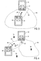
- Fig. 3 shows schematically two elements of a wireless communication system according to an embodiment of the present invention.
- the first element is a guest (20) having means for transmitting guest signals which include a guest transmitter (25).
- the guest transmitter (25) comprises a transmission element capable of transmitting signals of radiofrequency (RF) or of the infrared (IR) type or any other type.
- the second element is a host (10) having means for receiving guest signals which include a host receiver (15).
- the host receiver (15) comprises a reception element capable of receiving signals of the type transmitted by the guest.
- the host (10) When the guest (20) transmits a declaration signal (50) from within a declaration area (40) of the host (10), i.e. while the guest transmitter (25) is located within this declaration area (40), the host (10) establishes the link with the guest (20) upon reception of said declaration signal (50). Conversely, when the guest (20) transmits the declaration signal (50) from outside the declaration area (40) of the host (10), i.e. while the guest transmitter (25) is located outside this declaration area (40), the host (10) does not establish the link with the guest (20).
- Said declaration area (40) is an area which is substantially different from the normal operating area (60) of the guest/host pair, although it may partially be overlapped by the normal operating area (60) as shown in Fig. 3 , or even be substantially overlapped by the normal operating area (60) as will be described below for a preferred embodiment as illustrated in Fig 5 .
- a host 10 whose host receiver (15) comprises two distinct host receiver sensors, the characteristics and the position of a first sensor determining the declaration area (40) and the characteristics and the position of a second sensor determining the normal operating area (60).
- the user can thus establish a link between a selected guest and a selected host by simply bringing the selected guest's transmitter in the declaration area of the selected host and by triggering the transmission of the declaration signal from this position.
- the user can, for example simply push a particular button or sensor on the guest (20); this further simplifies the process.
- a simple combination of buttons and/or sensors may also be used in order to reduce the risk of accidental triggering.
- a direct action on the host (10) for establishing said link is superfluous. This aspect may constitute an additional advantage of the present invention, for example in case the host is out of reach of the user, or if, for aesthetic reasons, one does not wish to have buttons or any other means to trigger the request stage on the host.
- Fig. 3 there are also indicated examples of other positions (21,22) of the guest transmitter (25) which will be treated by the system as being within the declaration area (40) and examples of further positions (70,71,72) of the guest transmitter (25) which will be treated by the system as being outside the declaration area (40).
- the declaration area (40) of the host (10) extends around the host receiver (15) and is substantially smaller than and included in the normal operating area (60) of the guest transmitter (25)/ host receiver (15) pair as shown schematically in Fig. 4 .
- a single host receiver sensor is sufficient for handling both the declaration signal (50) and the regular operation signals.
- the declaration areas of the various hosts of the wireless communication system are preferably arranged so as to not overlap each other.
- the host (10) of a system according to a most preferred embodiment of the invention has a declaration area (40) whose radius does not exceed 10% of the radius of the normal operating area (60) of the guest transmitter (25)/ host receiver (15) pair, said radius being measured from the host receiver (15). This characteristic provides, moreover, for simple distinction between both areas, thereby further simplifying the required circuitry.
- the guest (20) uses substantially the same transmission power for transmitting the declaration signal (50) and for transmitting the regular operation signals, all other things being equal of course (such as the state of charge of a host battery power supply).
- the host (10) determines the origin of the declaration signal (50) by measuring the signal strength of the received declaration signal (50). If said signal strength is greater than or equal to a first threshold, the host (10) concludes that the declaration signal (50) is being sent by the guest (20) from within his declaration area (40), i.e. while the guest transmitter (25) is located within his declaration area (40), and the host (10) consequently establishes the link with the guest (20).
- the host (10) concludes that the declaration signal (50) is being sent by the guest (20) from outside his declaration area (40), i.e. while the guest transmitter (25) is located outside his declaration area (40), and the host (10), consequently does not establish the link with the guest (20).
- a second threshold being substantially smaller than the first threshold
- the guest (20) uses a first transmission power for transmitting the declaration signal (50) and a second transmission power for transmitting the regular operation signals, the first transmission power being substantially lower than the second transmission power, all other things being equal of course (such as the state of charge of a host battery power supply).
- the declaration area (40) in such other embodiment corresponds to the area in which the guest transmitter (25) has to be located while transmitting the declaration signal (50) so as to be received by the host (10) with a signal/noise ratio higher than said minimum
- the normal operating area (60) corresponds to the area in which the guest transmitter (25) has to be located while transmitting the regular operating signals so as to be received by the host (10) with a signal/noise ratio higher than said minimum.
- the first transmission power being substantially lower than the second transmission power
- the declaration area (40) will, consequently, be substantially smaller than the normal operating area (60).
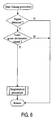
- the host (10) need not check the origin of the declaration signal (50). Indeed, if the host (10) receives a valid declaration signal (50), it inherently means that it is being sent from within his declaration area (40), and the host (10) will establish the link with the guest (20). If the guest (20) sends the declaration signal (50) from outside the host's declaration area (40), the host (10) will not detect the declaration signal (50) because its signal/noise ratio is lower than said minimum, and no link will be established with the guest (20).
- the advantage of such other embodiment is that the host (10) basically does not need any particular means for determining the transmission origin of the declaration signal (50).
- An exemplary process implemented on the host (10) in such an embodiment is shown in Fig. 6 .
- the disadvantage is that it requires a differentiation at the end of the guest (20) for sending signals of different power.
- the host (10) need not transmit signals to the guest (20) for establishing a link with said guest. Therefore, in embodiments, the host (10) does not comprise a transmitter for intentionally transmitting signals to a guest (20). This simplifies the system and, consequently, reduces its cost. In preferred embodiments, the host (10) does not comprise a transmitter for intentionally transmitting signals.
- the guest (20) need not have a receiver for intentionally receiving signals from a host (10).
- the guest (20) does not comprise a receiver for intentionally receiving signals.
- the host (10) may comprise means for indicating to the user that the link is effectively established with the guest (20).
- Such indication may, for example, consist in temporarily switching on a light or emitting a sound.
- Such an indication means is particularly advantageous in case the host (10) does not comprise a transmitter and the guest (20) does not comprise a receiver, because in the case the host (10) has no possibility for indicating to the guest (20) that the link has been established with the guest (20) and hence the guest (20) has no possibility for indicating the same to the user.
- the guest (20) can be linked to a plurality of hosts simply by applying the linking procedure according to the invention with for of these hosts.
- the host (10) can be linked to a plurality of guests simply by applying the linking procedure according to the invention for each of these guests.
- a guest (20) can be linked to a plurality of hosts and a host (10) can be linked to a plurality of guests in conformity with the two examples above.
- the simplified selection and linking procedure according to the invention may advantageously be applied conversely to the system for a simplified unlinking of a selected guest (20) from a selected host (10) whereto the selected guest (20) was previously linked.
- the system comprises means for breaking up the link with the guest (20) upon reception by the host (10) of an unlinking signal transmitted by the guest (20) while the guest transmitter (25) is located within the declaration area (40) of the host (10), said means not breaking up the link with the guest (20) upon transmission of the unlinking signal by the guest (20) while the guest transmitter (25) is located outside said declaration area (40). Subsequent to breaking up the link, the host (10) will not respond to regular operation signals transmitted by the guest (20), as was the case prior to linking the host (10) with the guest (20), until any further linking.
- the host (10) comprises means for indicating to the user that the link to the guest (20) is effectively broken up.
- Such indication may, for example, consist in temporarily switching on a light or emitting a sound.
- Such an indication means is particularly advantageous in case the host (10) does not comprise a transmitter and the guest (20) does not comprise a receiver, because in that case the host (10) has no possibility for indicating to the guest (20) that the link with the guest has been broken up and hence the guest (20) has no possibility for indicating the same to the user.
- a system comprising at least one host and at least one guest communicating with each other via a wireless medium and having means for linking a selected host (10) to a selected guest (20).
- the host (10) has means for establishing the link on the double condition that the guest (20) transmits a declaration signal (50) and that this declaration signal (50) is transmitted from within a declaration area (40) of the host (10), which declaration area differs substantially from the normal operating area (60) of the guest/host pair.
- the selection and the linking of the host (10) and the guest (20) is performed simply by putting the selected guest (20) in the declaration area (40) of the selected host (10) and by triggering the transmission of a declaration signal (50) by the selected guest (20) from within this declaration area (40).
Claims (12)
- Drahtloses Kommunikationssystem mit wenigstens einem Gast (20) mit Mitteln mit einem Gastsender (25) zum Übertragen von Gastsignalen und mit wenigstens einem Gastgeber (10) mit Mitteln mit einem Gastgeberempfänger (15) zum Empfangen der Gastsignale, wobei der genannte Gastgeber(10) Mittel aufweist zum Bilden einer Kopplung mit dem Gast (20), und zwar bei Empfang eines Ankündigungssignals (50), übertragen durch den Gast (20), wonach der Gastgeber (10) auf die normalen von dem gekoppelten Gast übertragenen Betriebssignale reagiert, wobei das System weiterhin Mittel aufweist zum Bilden der Kopplung mit dem Gast (20), und zwar bei Empfang des von dem Gast (20) übertragenen Ankündigungssignals (50) durch den Gastgeber (10), während der Gastsender (25) sich innerhalb des Ankündigungsgebietes (40) des Gastgebers (10) befindet, wobei das genannte Ankündigungsgebiet (40) ein Gebiet ist, das von dem normal funktionierenden Gebiet (60) des Gast/Gastgeberpaares wesentlich abweicht, und wobei die genannten Mittel bei Übertragung des Ankündigungssignals (50) durch den Gast (20) nicht die Kopplung mit dem Gast (20) bilden während der Gastsender (25) sich außerhalb des genannten Ankündigungsgebietes (40) befindet,
dadurch gekennzeichnet, dass
der Gast (20) im Wesentlichen die gleiche Übertragungsleistung zum Übertragen des Ankündigungssignals (5) wie zum Übertragen der normalen Betriebssignale anwendet, wobei der genannte Gastgeber (10) dazu vorgesehen ist, den Ursprung des Ankündigungssignals (50) zu ermitteln, und zwar durch Messung der Signalstärke des empfangenen Ankündigungssignals (50), wobei das Ankündigungsgebiet (40) durch eine erste Schwelle derart definiert wird, dass, wenn die gemessene Signalstärke größer ist als die genannte erste Schwelle oder derselben entspricht, bestimmt wird, dass das gemessene Signal aus dem genannten Ankündigungsgebiet (40) gesendet wird. - Drahtloses Kommunikationssystem nach Anspruch 1, dadurch gekennzeichnet, dass das Ankündigungsgebiet (40) sich um den Gastgeberempfänger (15) herum erstreckt und wesentlich kleiner ist als das normale Betriebsgebiet (60) des Gastsender/Gastgeberempfängerpaares (25) und in diesen Gebiet eingeschlossen ist.
- Drahtloses Kommunikationssystem nach Anspruch 2, dadurch gekennzeichnet, dass der Radius des Ankündigungsgebietes (40) 10% des Radius des normalen Betriebsgebietes (60) des Paares Gastsender (25) / Gastgeberempfänger (15) nicht übersteigt, wobei der Radium von dem Gastgeberempfänger (15) aus gemessen wird.
- Drahtloses Kommunikationssystem nach einem der vorstehenden Ansprüche, dadurch gekennzeichnet, dass der Gast (20) eine erste Übertragungsleistung zum Übertragen des Ankündigungssignals (50) und eine zweite Übertragungsleistung zum Übertragen der normalen Betriebssignale benutzt, wobei die erste Übertragungsleistung wesentlich niedriger ist als die zweite Übertragungsleistung.
- Drahtloses Kommunikationssystem nach einem der vorstehenden Ansprüche, dadurch gekennzeichnet, dass der Gastgeber (10) Mittel aufweist um einem Benutzer bekannt zu geben, dass die Kopplung mit dem Gast auf effektive Art und Weise hergestellt worden ist.
- Drahtloses Kommunikationssystem nach einem der vorstehenden Ansprüche, dadurch gekennzeichnet, dass das System Mittel aufweist um die Kopplung mit dem Gast (20) bei Empfang eines von dem Gast (20) übertragenen Entkopplungssignals zu abzubrechen, während der Gastsender (25) sich innerhalb des Ankündigungsgebietes (40) des Gastgebers (10) befindet, wobei die genannten Mittel die Kopplung mit dem Gast (20) bei Übertragung des Gastentkopplungssignals durch den Gast (20) nicht abbrechen, während der Gastsender (25) sich außerhalb des genannten Ankündigungsgebietes (40) befindet.
- Drahtloses Kommunikationssystem nach Anspruch 6, dadurch gekennzeichnet, dass der Gastgeber (10) Mittel aufweist um einem Benutzer bekannt zu geben, dass die Kopplung mit dem Gast (20) auf effektive Art und Weise abgebrochen ist.
- Gastgeber (10) eines drahtlosen Kommunikationssystems mit wenigstens einem Gast (20) und wenigstens einem Gastgeber (20) mit Mitteln, die einen Gastsender (25) zum Übertragen von Gastsignalen aufweisen, wobei der genannte Gastgeber (10) Mittel aufweist, die einen Gastgeberempfänger (15) zum Empfangen der Gastsignale und Mittel zum Herstellen einer Kopplung mit dem Gast (20) enthalten, und zwar bei Empfang eines von dem Gast (20) übertragenen Ankündigungssignals (50), wonach der Gastgeber (10) auf normale von dem gekoppelten Gast übertragene Betriebssignale reagiert, wobei der Gastgeber (10) Mittel aufweist zum Herstellen der Kopplung mit dem Gast (20), und zwar bei Empfang des von dem Gast (20) übertragenen Ankündigungssignals (50) während der Gastsender (25) sich innerhalb eines Ankündigungsgebietes (40) des Gastgebers (10) befindet, wobei das genannte Ankündigungsgebiet (40) ein Gebiet ist. Das von dem normalen Betriebsgebiet (6) des Paares Gast / Gastgeber wesentlich abweicht, und wobei die genannten Mittel die Kopplung mit dem Gast (20) bei Empfang des Ankündigungssignals (50) durch den Gast (20) nicht herstellen, während der Gastsender (25) sich außerhalb des genannten Ankündigungsgebietes (40) befindet,
dadurch gekennzeichnet, dass
der Gast (20) im Wesentlichen die gleiche Übertragungsleistung zur Übertragung des Ankündigungssignals (50) wie zur Übertragung normaler Betriebssignale verwendet, wobei der genannte Gastgeber (10) dazu vorgesehen ist, den Ursprung des Ankündigungssignals (50) zu ermitteln, und zwar durch Messung der Signalstärke des empfangenen Ankündigungssignals, wobei das Ankündigungsgebiet (40) durch eine erste Schwelle derart definiert wird, dass, wenn die gemessene Signalstärke größer ist als die genannte erste Schwelle oder derselben entspricht, bestimmt wird, dass das gemessene Signal aus dem genannten Ankündigungsgebiet (40) gesendet wird. - Gast (20) eines drahtlosen Kommunikationssystems mit wenigstens einem Gast und wenigstens einem Gastgeber (10), wobei der genannte Gast (20) Mittel aufweist mit einem Gastsender (25) zum Übertragen von Gastsignalen (20), wobei der genannte Gastgeber (10) Mittel aufweist, die einen Gastgeberempfänger (15) zum Empfangen der Gastsignale, und Mittel zum Herstellen einer Kopplung mit dem Gast (20) bei Empfang eines von dem Gast übertragenen Ankündigungssignals (50), wonach der Gastgeber (10) auf normale von dem gekoppelten Gast übertragene Betriebssignale reagiert, wobei der Gast (20) eine erste Übertragungsleistung zum Übertragen des Ankündigungssignals (50) und eine zweite Übertragungsleistung zum Übertragen der normalen Betriebssignale benutzt, wobei die erste Übertragungsleistung wesentlich niedriger ist als die zweite Übertragungsleistung,
dadurch gekennzeichnet, dass
der Gast (20) im Wesentlichen die gleiche Übertragungsleistung zum Übertragen des Ankündigungssignals (50) und zum Übertragen normaler Betriebssignale benutzt, wobei der genannte Gastgeber (10) dazu vorgesehen ist, den Ursprung des Ankündigungssignals (50) zu ermitteln, und zwar durch Messung der Signalstärke des empfangenen Ankündigungssignals, wobei das Ankündigungsgebiet (40) durch eine erste Schwelle derart definiert wird, dass, wenn die gemessene Signalstärke größer ist als die genannte erste Schwelle, oder derselben entspricht, das gemessene Signal von innerhalb des Ankündigungsgebietes (40) gesendet werden soll. - Verfahren zum Herstellen einer Kopplung zwischen einem Gastgeber (10) mit einem Gastgeberempfänger (15) und einem Gast (20) mit einem Gastsender (25) eines drahtlosen Kommunikationssystems mit wenigstens einem Gastgeber und wenigstens einem Gast, wonach der Gastgeber (10) auf normale von dem gekoppelten Gast (20) übertragene Betriebssignale reagieren wird, wobei das genannte Verfahren die nachfolgenden Verfahrensschritte umfasst:a) das Platzieren des Gastsenders (25) in das Ankündigungsgebiet (40) des Gastgebers (10), wobei das genannte Ankündigungsgebiet (40) wesentlich anders integrierte Schaltung als ein normales Betriebsgebiet (60) des Paares Gastsender (25) / Gastgeberempfänger (15);b) das Durchführen eines Benutzervorgangs an dem Gast (20), wobei in Reaktion darauf der Gast (20) ein Ankündigungssignals (50) überträgt; undc) das Herstellen der Kopplung zwischen dem Gastgeber (10) und dem Gast (20), wenn ein Übertragungsursprung des Ankündigungssignals (50) innerhalb des Ankündigungsgebietes (40) liegt und das nicht Herstellen der genannten Kopplung, wenn der Übertragungsursprung außerhalb des Ankündigungsgebietes (40) liegt,
dadurch gekennzeichnet, dass
der Gast (20) im Wesentlichen die gleiche Übertragungsleistung zum Übertragen des Ankündigungssignals (50) wie zum Übertragen normaler Betriebssignale benutzt, wobei das Verfahren weiterhin die nachfolgenden Verfahrensschritte umfasst:d) das Ermitteln des Ursprungs des Ankündigungssignals (50) durch Messung der Signalstärke des empfangenen Ankündigungssignals (50), wobei das Ankündigungsgebiet (40) durch eine erste Schwelle derart definiert wird, dass, wenn die gemessene Signalstärke größer ist als die genannte erste Schwelle oder derselben entspricht, das gemessene Signal von innerhalb des genannten Ankündigungsgebietes (40) gesendet wird. - Verfahren nach Anspruch 10, dadurch gekennzeichnet, dass das Ankündigungsgebiet (40) sich um den Gastgeberempfänger (15) herum erstreckt und wesentlich kleiner ist als das normale Betriebsgebiet (60) des Paares Gastsender (25) / Gastgeberempfänger (15) und darin aufgenommen ist.
- Verfahren nach Anspruch 11, dadurch gekennzeichnet, dass die Größe des Ankündigungsgebietes (40) 10% der Größe des normalen Betriebsgebietes (60) des Paares Gastsender (25) / Gastgeberempfänger (15) nicht übersteigt.
Priority Applications (1)
| Application Number | Priority Date | Filing Date | Title |
|---|---|---|---|
| EP02735806A EP1402686B1 (de) | 2001-06-19 | 2002-06-11 | Drahtloses kommunikationssystem |
Applications Claiming Priority (4)
| Application Number | Priority Date | Filing Date | Title |
|---|---|---|---|
| EP01202373 | 2001-06-19 | ||
| EP01202373 | 2001-06-19 | ||
| PCT/IB2002/002200 WO2002103962A2 (en) | 2001-06-19 | 2002-06-11 | Wireless communication system |
| EP02735806A EP1402686B1 (de) | 2001-06-19 | 2002-06-11 | Drahtloses kommunikationssystem |
Publications (2)
| Publication Number | Publication Date |
|---|---|
| EP1402686A2 EP1402686A2 (de) | 2004-03-31 |
| EP1402686B1 true EP1402686B1 (de) | 2008-09-03 |
Family
ID=8180506
Family Applications (1)
| Application Number | Title | Priority Date | Filing Date |
|---|---|---|---|
| EP02735806A Expired - Lifetime EP1402686B1 (de) | 2001-06-19 | 2002-06-11 | Drahtloses kommunikationssystem |
Country Status (8)
| Country | Link |
|---|---|
| US (1) | US7092694B2 (de) |
| EP (1) | EP1402686B1 (de) |
| JP (1) | JP2004521564A (de) |
| KR (1) | KR20030027957A (de) |
| CN (1) | CN1518815A (de) |
| AT (1) | ATE407496T1 (de) |
| DE (1) | DE60228708D1 (de) |
| WO (1) | WO2002103962A2 (de) |
Families Citing this family (27)
| Publication number | Priority date | Publication date | Assignee | Title |
|---|---|---|---|---|
| US9207905B2 (en) | 2003-07-28 | 2015-12-08 | Sonos, Inc. | Method and apparatus for providing synchrony group status information |
| US11106424B2 (en) | 2003-07-28 | 2021-08-31 | Sonos, Inc. | Synchronizing operations among a plurality of independently clocked digital data processing devices |
| US8086752B2 (en) | 2006-11-22 | 2011-12-27 | Sonos, Inc. | Systems and methods for synchronizing operations among a plurality of independently clocked digital data processing devices that independently source digital data |
| US8290603B1 (en) | 2004-06-05 | 2012-10-16 | Sonos, Inc. | User interfaces for controlling and manipulating groupings in a multi-zone media system |
| US11294618B2 (en) | 2003-07-28 | 2022-04-05 | Sonos, Inc. | Media player system |
| US11650784B2 (en) | 2003-07-28 | 2023-05-16 | Sonos, Inc. | Adjusting volume levels |
| US8234395B2 (en) | 2003-07-28 | 2012-07-31 | Sonos, Inc. | System and method for synchronizing operations among a plurality of independently clocked digital data processing devices |
| US11106425B2 (en) | 2003-07-28 | 2021-08-31 | Sonos, Inc. | Synchronizing operations among a plurality of independently clocked digital data processing devices |
| US9977561B2 (en) | 2004-04-01 | 2018-05-22 | Sonos, Inc. | Systems, methods, apparatus, and articles of manufacture to provide guest access |
| US8024055B1 (en) | 2004-05-15 | 2011-09-20 | Sonos, Inc. | Method and system for controlling amplifiers |
| US8326951B1 (en) | 2004-06-05 | 2012-12-04 | Sonos, Inc. | Establishing a secure wireless network with minimum human intervention |
| US8868698B2 (en) | 2004-06-05 | 2014-10-21 | Sonos, Inc. | Establishing a secure wireless network with minimum human intervention |
| DE102005009504B3 (de) * | 2005-03-02 | 2006-03-09 | Fraunhofer-Gesellschaft zur Förderung der angewandten Forschung e.V. | Mobilteil und Basisstation für ein Kommunikationsprotokoll mit einer Normal-Anmeldung und einer Ad-hoc-Anmeldung |
| US9202509B2 (en) | 2006-09-12 | 2015-12-01 | Sonos, Inc. | Controlling and grouping in a multi-zone media system |
| US8788080B1 (en) | 2006-09-12 | 2014-07-22 | Sonos, Inc. | Multi-channel pairing in a media system |
| US8483853B1 (en) | 2006-09-12 | 2013-07-09 | Sonos, Inc. | Controlling and manipulating groupings in a multi-zone media system |
| US11265652B2 (en) | 2011-01-25 | 2022-03-01 | Sonos, Inc. | Playback device pairing |
| US11429343B2 (en) | 2011-01-25 | 2022-08-30 | Sonos, Inc. | Stereo playback configuration and control |
| US8938312B2 (en) | 2011-04-18 | 2015-01-20 | Sonos, Inc. | Smart line-in processing |
| US9042556B2 (en) | 2011-07-19 | 2015-05-26 | Sonos, Inc | Shaping sound responsive to speaker orientation |
| US9729115B2 (en) | 2012-04-27 | 2017-08-08 | Sonos, Inc. | Intelligently increasing the sound level of player |
| US9008330B2 (en) | 2012-09-28 | 2015-04-14 | Sonos, Inc. | Crossover frequency adjustments for audio speakers |
| US9244516B2 (en) | 2013-09-30 | 2016-01-26 | Sonos, Inc. | Media playback system using standby mode in a mesh network |
| US9226073B2 (en) | 2014-02-06 | 2015-12-29 | Sonos, Inc. | Audio output balancing during synchronized playback |
| US9226087B2 (en) | 2014-02-06 | 2015-12-29 | Sonos, Inc. | Audio output balancing during synchronized playback |
| US10248376B2 (en) | 2015-06-11 | 2019-04-02 | Sonos, Inc. | Multiple groupings in a playback system |
| US10712997B2 (en) | 2016-10-17 | 2020-07-14 | Sonos, Inc. | Room association based on name |
Family Cites Families (9)
| Publication number | Priority date | Publication date | Assignee | Title |
|---|---|---|---|---|
| GB2228162B (en) * | 1989-02-08 | 1993-05-19 | Philips Electronic Associated | Mobile radio transmission system and a mobile station for use in the system |
| SE514018C2 (sv) * | 1993-09-23 | 2000-12-11 | Ericsson Telefon Ab L M | Metod för registrering i ett cellindelat mobilradiosystem |
| US5610969A (en) * | 1994-12-23 | 1997-03-11 | Bell Atlantic Mobile Systems, Inc. | Personal communication service registration system and method |
| US5640756A (en) * | 1995-02-08 | 1997-06-24 | Gencorp Inc. | Manufacturing system |
| EP0882364A4 (de) * | 1996-01-11 | 1999-07-07 | Aptel Ltd | Drahtlose anordnung für nachrichtendienst |
| US6035193A (en) * | 1996-06-28 | 2000-03-07 | At&T Wireless Services Inc. | Telephone system having land-line-supported private base station switchable into cellular network |
| KR20010034829A (ko) * | 1998-04-27 | 2001-04-25 | 비센트 비.인그라시아 | 통신 시스템에서 이동국 위치 등록을 위한 방법 및 장치 |
| US6148205A (en) * | 1998-06-30 | 2000-11-14 | Motorola, Inc. | Method and apparatus for secure registration within an in-home wireless network |
| CA2323881A1 (en) * | 2000-10-18 | 2002-04-18 | Dps Wireless Inc. | Adaptive personal repeater |
-
2002
- 2002-06-11 DE DE60228708T patent/DE60228708D1/de not_active Expired - Fee Related
- 2002-06-11 KR KR10-2003-7002372A patent/KR20030027957A/ko not_active Application Discontinuation
- 2002-06-11 WO PCT/IB2002/002200 patent/WO2002103962A2/en active IP Right Grant
- 2002-06-11 JP JP2003506145A patent/JP2004521564A/ja active Pending
- 2002-06-11 EP EP02735806A patent/EP1402686B1/de not_active Expired - Lifetime
- 2002-06-11 CN CNA028122631A patent/CN1518815A/zh active Pending
- 2002-06-11 AT AT02735806T patent/ATE407496T1/de not_active IP Right Cessation
- 2002-06-19 US US10/175,413 patent/US7092694B2/en not_active Expired - Lifetime
Also Published As
| Publication number | Publication date |
|---|---|
| DE60228708D1 (de) | 2008-10-16 |
| WO2002103962A3 (en) | 2003-10-02 |
| EP1402686A2 (de) | 2004-03-31 |
| JP2004521564A (ja) | 2004-07-15 |
| US20030069012A1 (en) | 2003-04-10 |
| US7092694B2 (en) | 2006-08-15 |
| WO2002103962A2 (en) | 2002-12-27 |
| CN1518815A (zh) | 2004-08-04 |
| ATE407496T1 (de) | 2008-09-15 |
| KR20030027957A (ko) | 2003-04-07 |
Similar Documents
| Publication | Publication Date | Title |
|---|---|---|
| EP1402686B1 (de) | Drahtloses kommunikationssystem | |
| US5884156A (en) | Portable communication device | |
| US20020111140A1 (en) | Wireless headset capable of automatic link connection and method for controlling the same | |
| WO2003021818A8 (en) | Dual mode radio communication apparatus | |
| JP2003152621A (ja) | 無線通信装置および電子機器 | |
| US7096001B2 (en) | Security system with telephone controller | |
| US5732335A (en) | Externally controlled output power by means of antenna keying | |
| KR100619418B1 (ko) | 위치 확인 방법 | |
| EP2866470B1 (de) | Privates Audiostreaming an einer Verkaufsstelle | |
| EP1446780B1 (de) | Tragbares alarmsystem, das an das persönliche funkgerät einer einzelperson angeschaltet ist | |
| JPH0834627B2 (ja) | チャネル選択方式 | |
| JP2906603B2 (ja) | 視覚障害者用交通信号機制御システム | |
| KR20080058873A (ko) | 블루투스 디바이스를 연결하기 위한 장치 및 방법 | |
| US6201472B1 (en) | Wireless communication system with increased dynamic range | |
| JP2002084210A5 (de) | ||
| JP3843788B2 (ja) | 遠隔制御監視システムの端末機能の設定方式 | |
| JP3633529B2 (ja) | ワイヤレスコールシステム | |
| JP2989574B2 (ja) | コードレス電話機 | |
| JP3627555B2 (ja) | 通信システムおよび通信アダプタ | |
| JP2002071829A (ja) | レーザ出力用中継装置および移動体の通過検知システム | |
| JPH08289358A (ja) | コードレス電話システムにおけるコードレス電話機の位置推定装置および推定方法 | |
| JPH01232413A (ja) | 端末装置 | |
| JP2000261365A (ja) | 単信方式通信システム | |
| JPH0539047U (ja) | 電界強度測定機能を有したコードレス電話機 | |
| JPH11205182A (ja) | 送受信機 |
Legal Events
| Date | Code | Title | Description |
|---|---|---|---|
| PUAI | Public reference made under article 153(3) epc to a published international application that has entered the european phase |
Free format text: ORIGINAL CODE: 0009012 |
|
| AK | Designated contracting states |
Kind code of ref document: A2 Designated state(s): AT BE CH CY DE DK ES FI FR GB GR IE IT LI LU MC NL PT SE TR |
|
| 17P | Request for examination filed |
Effective date: 20040402 |
|
| GRAP | Despatch of communication of intention to grant a patent |
Free format text: ORIGINAL CODE: EPIDOSNIGR1 |
|
| GRAS | Grant fee paid |
Free format text: ORIGINAL CODE: EPIDOSNIGR3 |
|
| GRAA | (expected) grant |
Free format text: ORIGINAL CODE: 0009210 |
|
| AK | Designated contracting states |
Kind code of ref document: B1 Designated state(s): AT BE CH CY DE DK ES FI FR GB GR IE IT LI LU MC NL PT SE TR |
|
| REG | Reference to a national code |
Ref country code: GB Ref legal event code: FG4D |
|
| REG | Reference to a national code |
Ref country code: CH Ref legal event code: EP |
|
| REG | Reference to a national code |
Ref country code: IE Ref legal event code: FG4D |
|
| REF | Corresponds to: |
Ref document number: 60228708 Country of ref document: DE Date of ref document: 20081016 Kind code of ref document: P |
|
| PG25 | Lapsed in a contracting state [announced via postgrant information from national office to epo] |
Ref country code: ES Free format text: LAPSE BECAUSE OF FAILURE TO SUBMIT A TRANSLATION OF THE DESCRIPTION OR TO PAY THE FEE WITHIN THE PRESCRIBED TIME-LIMIT Effective date: 20081214 Ref country code: NL Free format text: LAPSE BECAUSE OF FAILURE TO SUBMIT A TRANSLATION OF THE DESCRIPTION OR TO PAY THE FEE WITHIN THE PRESCRIBED TIME-LIMIT Effective date: 20080903 |
|
| PG25 | Lapsed in a contracting state [announced via postgrant information from national office to epo] |
Ref country code: AT Free format text: LAPSE BECAUSE OF FAILURE TO SUBMIT A TRANSLATION OF THE DESCRIPTION OR TO PAY THE FEE WITHIN THE PRESCRIBED TIME-LIMIT Effective date: 20080903 Ref country code: FI Free format text: LAPSE BECAUSE OF FAILURE TO SUBMIT A TRANSLATION OF THE DESCRIPTION OR TO PAY THE FEE WITHIN THE PRESCRIBED TIME-LIMIT Effective date: 20080903 |
|
| NLV1 | Nl: lapsed or annulled due to failure to fulfill the requirements of art. 29p and 29m of the patents act | ||
| PG25 | Lapsed in a contracting state [announced via postgrant information from national office to epo] |
Ref country code: BE Free format text: LAPSE BECAUSE OF FAILURE TO SUBMIT A TRANSLATION OF THE DESCRIPTION OR TO PAY THE FEE WITHIN THE PRESCRIBED TIME-LIMIT Effective date: 20080903 |
|
| REG | Reference to a national code |
Ref country code: GB Ref legal event code: 732E Free format text: REGISTERED BETWEEN 20090312 AND 20090318 |
|
| PG25 | Lapsed in a contracting state [announced via postgrant information from national office to epo] |
Ref country code: PT Free format text: LAPSE BECAUSE OF FAILURE TO SUBMIT A TRANSLATION OF THE DESCRIPTION OR TO PAY THE FEE WITHIN THE PRESCRIBED TIME-LIMIT Effective date: 20090203 |
|
| PLBE | No opposition filed within time limit |
Free format text: ORIGINAL CODE: 0009261 |
|
| STAA | Information on the status of an ep patent application or granted ep patent |
Free format text: STATUS: NO OPPOSITION FILED WITHIN TIME LIMIT |
|
| PG25 | Lapsed in a contracting state [announced via postgrant information from national office to epo] |
Ref country code: DK Free format text: LAPSE BECAUSE OF FAILURE TO SUBMIT A TRANSLATION OF THE DESCRIPTION OR TO PAY THE FEE WITHIN THE PRESCRIBED TIME-LIMIT Effective date: 20080903 |
|
| 26N | No opposition filed |
Effective date: 20090604 |
|
| PG25 | Lapsed in a contracting state [announced via postgrant information from national office to epo] |
Ref country code: IT Free format text: LAPSE BECAUSE OF FAILURE TO SUBMIT A TRANSLATION OF THE DESCRIPTION OR TO PAY THE FEE WITHIN THE PRESCRIBED TIME-LIMIT Effective date: 20080903 |
|
| PG25 | Lapsed in a contracting state [announced via postgrant information from national office to epo] |
Ref country code: MC Free format text: LAPSE BECAUSE OF NON-PAYMENT OF DUE FEES Effective date: 20090630 Ref country code: SE Free format text: LAPSE BECAUSE OF FAILURE TO SUBMIT A TRANSLATION OF THE DESCRIPTION OR TO PAY THE FEE WITHIN THE PRESCRIBED TIME-LIMIT Effective date: 20081203 |
|
| REG | Reference to a national code |
Ref country code: CH Ref legal event code: PL |
|
| GBPC | Gb: european patent ceased through non-payment of renewal fee |
Effective date: 20090611 |
|
| REG | Reference to a national code |
Ref country code: FR Ref legal event code: ST Effective date: 20100226 |
|
| PG25 | Lapsed in a contracting state [announced via postgrant information from national office to epo] |
Ref country code: LI Free format text: LAPSE BECAUSE OF NON-PAYMENT OF DUE FEES Effective date: 20090630 Ref country code: CH Free format text: LAPSE BECAUSE OF NON-PAYMENT OF DUE FEES Effective date: 20090630 Ref country code: FR Free format text: LAPSE BECAUSE OF NON-PAYMENT OF DUE FEES Effective date: 20090630 Ref country code: IE Free format text: LAPSE BECAUSE OF NON-PAYMENT OF DUE FEES Effective date: 20090611 |
|
| PG25 | Lapsed in a contracting state [announced via postgrant information from national office to epo] |
Ref country code: GB Free format text: LAPSE BECAUSE OF NON-PAYMENT OF DUE FEES Effective date: 20090611 |
|
| PG25 | Lapsed in a contracting state [announced via postgrant information from national office to epo] |
Ref country code: DE Free format text: LAPSE BECAUSE OF NON-PAYMENT OF DUE FEES Effective date: 20100101 |
|
| PG25 | Lapsed in a contracting state [announced via postgrant information from national office to epo] |
Ref country code: GR Free format text: LAPSE BECAUSE OF FAILURE TO SUBMIT A TRANSLATION OF THE DESCRIPTION OR TO PAY THE FEE WITHIN THE PRESCRIBED TIME-LIMIT Effective date: 20081204 |
|
| PG25 | Lapsed in a contracting state [announced via postgrant information from national office to epo] |
Ref country code: LU Free format text: LAPSE BECAUSE OF NON-PAYMENT OF DUE FEES Effective date: 20090611 |
|
| PG25 | Lapsed in a contracting state [announced via postgrant information from national office to epo] |
Ref country code: TR Free format text: LAPSE BECAUSE OF FAILURE TO SUBMIT A TRANSLATION OF THE DESCRIPTION OR TO PAY THE FEE WITHIN THE PRESCRIBED TIME-LIMIT Effective date: 20080903 |
|
| PG25 | Lapsed in a contracting state [announced via postgrant information from national office to epo] |
Ref country code: CY Free format text: LAPSE BECAUSE OF FAILURE TO SUBMIT A TRANSLATION OF THE DESCRIPTION OR TO PAY THE FEE WITHIN THE PRESCRIBED TIME-LIMIT Effective date: 20080903 |