EP1402241B1 - Systeme de transmission de pression a dispositif de reconnaissance de rupture de membrane - Google Patents
Systeme de transmission de pression a dispositif de reconnaissance de rupture de membrane Download PDFInfo
- Publication number
- EP1402241B1 EP1402241B1 EP02743209A EP02743209A EP1402241B1 EP 1402241 B1 EP1402241 B1 EP 1402241B1 EP 02743209 A EP02743209 A EP 02743209A EP 02743209 A EP02743209 A EP 02743209A EP 1402241 B1 EP1402241 B1 EP 1402241B1
- Authority
- EP
- European Patent Office
- Prior art keywords
- pressure
- medium
- pressure chamber
- sensor
- unit
- Prior art date
- Legal status (The legal status is an assumption and is not a legal conclusion. Google has not performed a legal analysis and makes no representation as to the accuracy of the status listed.)
- Expired - Lifetime
Links
- 239000012528 membrane Substances 0.000 title abstract description 22
- 230000005540 biological transmission Effects 0.000 title description 9
- 239000000463 material Substances 0.000 claims abstract description 9
- 238000000034 method Methods 0.000 claims description 4
- 230000006835 compression Effects 0.000 claims 1
- 238000007906 compression Methods 0.000 claims 1
- 238000012544 monitoring process Methods 0.000 abstract description 8
- 239000000356 contaminant Substances 0.000 abstract description 5
- 238000009530 blood pressure measurement Methods 0.000 abstract description 3
- 238000000926 separation method Methods 0.000 description 13
- 239000011521 glass Substances 0.000 description 7
- 238000012546 transfer Methods 0.000 description 6
- 239000012535 impurity Substances 0.000 description 5
- 230000000295 complement effect Effects 0.000 description 3
- 238000011109 contamination Methods 0.000 description 3
- 238000001514 detection method Methods 0.000 description 3
- 239000012530 fluid Substances 0.000 description 3
- 239000007788 liquid Substances 0.000 description 3
- 238000004891 communication Methods 0.000 description 2
- 230000001419 dependent effect Effects 0.000 description 2
- 238000009792 diffusion process Methods 0.000 description 2
- 238000006073 displacement reaction Methods 0.000 description 2
- 238000011010 flushing procedure Methods 0.000 description 2
- 239000003921 oil Substances 0.000 description 2
- 239000000126 substance Substances 0.000 description 2
- 235000004035 Cryptotaenia japonica Nutrition 0.000 description 1
- 102000007641 Trefoil Factors Human genes 0.000 description 1
- 235000015724 Trifolium pratense Nutrition 0.000 description 1
- 230000000694 effects Effects 0.000 description 1
- 238000011156 evaluation Methods 0.000 description 1
- 238000009434 installation Methods 0.000 description 1
- 150000002500 ions Chemical class 0.000 description 1
- 238000004519 manufacturing process Methods 0.000 description 1
- 238000010926 purge Methods 0.000 description 1
- 239000000523 sample Substances 0.000 description 1
- 239000007787 solid Substances 0.000 description 1
- 238000001179 sorption measurement Methods 0.000 description 1
Images

Classifications
-
- G—PHYSICS
- G01—MEASURING; TESTING
- G01L—MEASURING FORCE, STRESS, TORQUE, WORK, MECHANICAL POWER, MECHANICAL EFFICIENCY, OR FLUID PRESSURE
- G01L19/00—Details of, or accessories for, apparatus for measuring steady or quasi-steady pressure of a fluent medium insofar as such details or accessories are not special to particular types of pressure gauges
- G01L19/06—Means for preventing overload or deleterious influence of the measured medium on the measuring device or vice versa
- G01L19/0672—Leakage or rupture protection or detection
-
- G—PHYSICS
- G01—MEASURING; TESTING
- G01L—MEASURING FORCE, STRESS, TORQUE, WORK, MECHANICAL POWER, MECHANICAL EFFICIENCY, OR FLUID PRESSURE
- G01L27/00—Testing or calibrating of apparatus for measuring fluid pressure
- G01L27/007—Malfunction diagnosis, i.e. diagnosing a sensor defect
-
- G—PHYSICS
- G01—MEASURING; TESTING
- G01M—TESTING STATIC OR DYNAMIC BALANCE OF MACHINES OR STRUCTURES; TESTING OF STRUCTURES OR APPARATUS, NOT OTHERWISE PROVIDED FOR
- G01M3/00—Investigating fluid-tightness of structures
- G01M3/02—Investigating fluid-tightness of structures by using fluid or vacuum
- G01M3/04—Investigating fluid-tightness of structures by using fluid or vacuum by detecting the presence of fluid at the leakage point
- G01M3/16—Investigating fluid-tightness of structures by using fluid or vacuum by detecting the presence of fluid at the leakage point using electric detection means
Definitions
- the invention relates to a pressure transmitter for transmitting a pressure from a prevailing in a first medium pressure on a second medium.
- the generic diaphragm seal are used inter alia in the pressure measurement in aggressive media, the separation membrane is acted upon by an aggressive first medium and the prevailing pressure in the first medium to a second medium in the pressure chamber transfers, from where it fed via a suitable pressure supply to a pressure measuring cell becomes.
- a pressure transmission with a pressure transmitter and a connected pressure line may also be desirable in non-aggressive media to bridge long distances between the first medium and the location of the pressure measuring cell.
- incompressible oils are used as the second medium.
- a medium is suitable for contaminating a measuring medium, and for various other reasons, it is necessary to detect a leak in the separating membrane or a rupture of the separating membrane at an early stage.
- Bastiaan discloses this in the European patent application EP 0 838 672 a pressure transmitter, wherein the pressure chamber adjacent to the pressure chamber opening has a second opening which is formed as a blind hole, in which the electrode of a conductivity sensor is arranged. If now the Separation membrane breaks, the first medium diffuses into the pressure chamber and into the second opening, after which a change in the conductivity is detectable if the first medium has a conductivity which differs substantially from that of the second medium. This is especially the case when the first medium is a corrosive medium and the second medium is an oil.
- the publication DE 42 35 684 A1 discloses a pressure gauge with a pressure transmitter and a purging device, which makes it possible to clean the pressure chamber of the pressure transmitter to remove diffused atoms, ions or molecules. A part of the rinsing liquid can be supplied to a sensor in order to detect a membrane rupture on the basis of the diffused substances. Although this solution may work in principle, it is very expensive due to the cost of the flushing device. During flushing, the pressure gauge is also not available for pressure measurement.
- the inventive device for transmitting a pressure from a prevailing in a first medium pressure by means of a second medium to a pressure measuring cell comprises a main body; a trefoil membrane, which is fastened with its edge to the main body, wherein the separation membrane can be brought into contact with the first medium with its first surface facing away from the base body, and with its second surface facing towards the base body and the base body forms a pressure chamber which can be filled with the second medium, the pressure chamber having a Druckschschfmung, a pressure supply line, which is in fluid communication with the pressure chamber via the Druckschdorffinung, wherein the pressure is to be transmitted by the pressure supply line by means of the second medium to a pressure measuring cell; and a sensor for monitoring a material property of the second medium, characterized, the sensor is in fluid communication with the pressure chamber via the pressure chamber opening.
- the senor is a conductivity sensor.
- the sensor may be a capacitive sensor that monitors the relative dielectric constant of the second medium.
- the material properties of the second medium are changed by impurities from the first medium.
- the sensor should preferably be at most far enough away from the separation membrane that the expected diffusion time of the contaminants from a leak in the membrane to the sensor does not exceed a predetermined period of time , Depending on the requirement, which is essentially predetermined by the field of application of the sensor, this time interval can be in the range of minutes, hours, days or weeks.
- the sensor element In order to use the diaphragm seal according to the invention as universally as possible, the sensor element should be arranged with the smallest possible distance to the separation membrane.
- the senor When the sensor is a conductivity sensor, it comprises at least two spaced-apart electrodes, the space between the electrodes being at least partially filled with the second medium.
- the sensor may comprise, for example, a first and a second electrode which are each electrically insulated from each other and with respect to the main body or a pressure supply line, or the sensor may comprise a first electrode which is isolated from the main body or a pressure supply line, wherein the main body or the pressure supply line serves as a counter electrode.
- a capacitive sensor may have the same arrangement of electrodes as a conductivity sensor.
- the main body of the pressure transmitter comprises a line connection for connection to a pressure supply line, by means of which the pressure is transmitted to a pressure transducer.
- the pressure chamber opening opens into this line connection.
- the sensor can now be arranged, for example, in the line connection or in a connection adapter with which the pressure supply line is connected to the line connection.
- the terminal adapter comprises a diaphragm seal connection, which is complementary to the line connection, and a pressure line receiving.
- the terminal adapter also includes a first electrode and a second electrode of the sensor.
- the pressure line intake for example, have a chamber in the connection adapter, in which the pressure supply line opens.
- the first electrode and the second electrode may be fixed, for example by means of a glass feedthrough in an opening of the chamber.
- the pressure feed line is also fastened by means of a glass feedthrough, in particular the same glass feedthrough.
- the arrangement of the sensor for monitoring a material property of the transfer medium in the pressure chamber opening or in another communicating with the pressure chamber via the pressure chamber opening portion has the further advantage that it also comes to a transport of contaminants by convection or by flow of the transfer medium.
- a displacement of the entire working volume in the event of an overload pressure impact means a displacement of the transmission medium in the opening by about 127 mm. In this way, the contamination with the transmission medium can reach the sensor much faster than is the case with the arrangement according to Bastiaan.
- a temperature change in the pressure feed line for example, 10 ° C leads at a volume expansion coefficient of about 10 -3 / K at a pressure feed length of 10 m and an inner diameter of 1 mm to a volume change of about 80 mm 3 , which is a shift of the liquid column of about 100 mm at the end of the pressure line.
- the described convective transport to the sensor is all the more effective, the greater the length of the pressure feed line in relation to the distance of the sensor from the separation membrane.
- the elements of the sensor for example, the electrodes of a conductivity sensor should be arranged as possible in a region of the pressure chamber opening, the pressure supply line, or a connection adapter between pressure transmitter and pressure supply, which is flowed through by the described convection or immediately adjacent to such a region ,
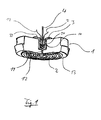
- the in Fig. 1 shown pressure transmitter comprises a base body 1, which preferably has a substantially cylindrically symmetrical structure. At the end face 13 of the body, a separation membrane 2 is attached with its edge 21, so that between the separation membrane 2 and the base body, a pressure chamber 11 is formed.
- the end face 13 of the main body 1 can be seen in the usual way with a membrane bed, against which the separation membrane 2 is pressed in case of overload.
- the pressure chamber 11 has an opening 12 for transmitting the pressure prevailing in the pressure chamber.
- the opening 12 is preferably formed as a capillary.
- the opening 12 extends as far as a pressure line connection 14, which is preferably designed as a substantially cylindrical or axially symmetrical recess in the end face of the base body 1 facing away from the separation membrane 2.
- connection of the pressure supply line 4 takes place in the preferred embodiment by means of a connection adapter 3, in which the sensor for monitoring a material property of the transmission medium is integrated. Details of the terminal adapter 3 will now be described with additional reference Fig. 2 described. The proportions of individual elements of in Fig. 2 shown embodiment of a connection adapter differ from those of the configuration of the connection adapter in Fig. 1 , In both drawings, however, identical reference numerals are used for corresponding elements.
- connection adapter 3 comprises a pressure medium connection 37 complementary to the line connection 14 and a pressure line receptacle which is formed in a preferably cylindrical first section 33.
- the connection adapter 3 also comprises a first electrode 31 and a second electrode 32 of the sensor.
- the Druckmiftleranschluß 37 may for example comprise a substantially cylindrical or conical projection which extends in the axial direction from an end face of the first portion 33 and has a channel 36 through which a flow connection between the pressure chamber opening 12 of the pressure transmitter 1 and the pressure line receiving is effected.
- the end face of the first portion outside the cylindrical protrusion serves as an axial abutment surface defining the position of the connection adapter 3 with respect to the base body 1 and at the same time a (possibly additional) seal between the base body 1 and the connection adapter 3 causes.
- the lateral surface 38 of the substantially cylindrical projection may optionally be provided with an external thread, which is complementary to an internal thread in the wall of the pressure line connection 14.
- the pressure line intake for example, have a chamber 35 in the connection adapter 3, in which the pressure supply line 4 opens.
- the sensor for monitoring a material property of the second medium in this case the electrical conductivity, is likewise arranged in the pressure line receptacle.
- the first electrode 31 and the second electrode 32 of the sensor may, for example, be fixed in an opening of the chamber 35 by means of a glass feedthrough 34.
- the pressure feed line is also by means of a glass feedthrough, fastened, in particular the same glass feedthrough 34 can be used.
- the chamber 35 should be sufficiently large so that the electrodes can be securely positioned isolated from one another, and so that a suitable space filled with the second medium or a transfer liquid extends between the electrodes.
- the transport of impurities into the environment of the electrodes should be as fast as possible. Therefore, as short as possible and direct paths should be given with large cross-sections between the channel 36 in the diaphragm seal connection 37 and the electrodes. Insofar as the channel 36 is also a portion of the path of contamination, the channel 36 should also have the lowest possible diffusion resistance.
- the total volume of the transfer fluid in the system is to be kept as low as possible in order to minimize the influence of temperature fluctuations on the overall system.
- only one electrode may be provided to measure the conductivity between it and the main body or the chamber.
- Pressure supply line 4 is preferably designed as a capillary line.
- the capillary is tubular, but it can also as a hole in a solid block, for example a Separator, be formed, in which the sensor and the pressure connection adapter or a pressure transmitter connection can be integrated.
- the pressure feed line transfers the pressure present in the second medium to a pressure measuring cell, not specified, which generates a pressure-dependent electrical signal.
- the electrodes 31, 32 of the conductivity sensor are connected to a suitable evaluation circuit, which monitors the conductivity of the transmission medium.
- the monitoring can be carried out, for example, continuously, periodically or event-controlled, for example on query by a microprocessor.
- the diaphragm seal according to the invention can in principle also have other sensors. Also suitable are u.a. Capacitive sensors, pH sensors, photometers or specific adsorption sensors, which detect the presence of a selected foreign substance from the first medium or the process medium in the transmission medium.
Landscapes
- Physics & Mathematics (AREA)
- General Physics & Mathematics (AREA)
- Health & Medical Sciences (AREA)
- Chemical & Material Sciences (AREA)
- Engineering & Computer Science (AREA)
- Analytical Chemistry (AREA)
- Biomedical Technology (AREA)
- Measuring Fluid Pressure (AREA)
Claims (8)
- Dispositif destiné à la transmission d'une pression régnant dans un premier produit au moyen d'un deuxième produit vers une cellule de mesure de pression, comprenant :- un corps de base (1) ;- une membrane de séparation (2), dont le bord est fixé au corps de base (1), la membrane de séparation (1) pouvant être amenée avec sa première surface - opposée au corps de base (1) - en contact avec le premier produit, et formant une chambre de pression (11) avec sa deuxième surface - faisant face au corps de base (1) - et le corps de base (1), chambre qui peut être remplie par le deuxième produit, la chambre de pression (11) présentant une ouverture de chambre de pression (12),- une conduite d'alimentation de pression, qui est en liaison d'écoulement avec la chambre de pression à travers l'ouverture de la chambre de pression, la pression étant transmise à travers la conduite d'alimentation de pression au moyen du deuxième produit vers une cellule de mesure de pression ; et- un capteur destiné à la surveillance d'une propriété du deuxième produit, le capteur étant en liaison d'écoulement avec la chambre de pression (11) par l'intermédiaire de l'ouverture de chambre de pression (12).
- Dispositif selon la revendication 1, pour lequel le capteur est un capteur de conductivité.
- Dispositif selon la revendication 2, pour lequel le capteur de conductivité comporte une première électrode (31) et une deuxième électrode (32), lesquelles sont disposées de telle manière à être isolées l'une par à l'autre, et par rapport au corps de base (1).
- Dispositif selon la revendication 2, pour lequel le capteur de conductivité comporte une électrode, laquelle est disposée de telle manière à être isolée par rapport au corps de base (1), afin de mesurer la conductivité du deuxième produit entre l'électrode et le corps de base, ou les composants reliés avec celui-ci au moyen d'une liaison conductrice.
- Dispositif selon la revendication 3, pour lequel la conduite d'alimentation de pression (4) est une conduite capillaire.
- Dispositif selon la revendication 3 ou 4, comprenant en outre un adaptateur de raccordement (3), qui relie la conduite d'alimentation de pression (4) avec l'ouverture de la chambre de pression.
- Dispositif selon la revendication 6, pour lequel l'adaptateur de raccordement (3) comprend le capteur.
- Dispositif selon l'une des revendications précédentes, pour lequel une mise en pression variable de la membrane de séparation et/ou une modification du volume du deuxième produit en raison de fluctuations de température conduit, à l'intérieur d'une plage de travail prédéfinie du dispositif, à un écoulement du deuxième produit à travers l'ouverture de la chambre de pression, le capteur étant disposé, par rapport à la chambre de pression, à une distance telle qu'au moins une partie du produit contenu dans la chambre de pression, à 50 % de la pression nominale et à la température moyenne de la plage de température nominale du dispositif, en cas de compression de la chambre de pression, s'écoule jusqu'au niveau du capteur d'un montant maximum de 30 %, de préférence d'un montant maximum de 20 % et particulièrement de préférence d'un montant maximum de 10 %.
Applications Claiming Priority (3)
| Application Number | Priority Date | Filing Date | Title |
|---|---|---|---|
| DE10131855 | 2001-06-30 | ||
| DE10131855A DE10131855A1 (de) | 2001-06-30 | 2001-06-30 | Druckmittler mit Vorrichtung zur Erkennung von Membranbrüchen und Anschlußadapter mit Vorrichtung zur Erkennung von Membranbrüchen |
| PCT/EP2002/006613 WO2003004984A1 (fr) | 2001-06-30 | 2002-06-15 | Systeme de transmission de pression a dispositif de reconnaissance de rupture de membrane et adaptateur de connexion a dispositif de reconnaissance de rupture de membrane |
Publications (2)
| Publication Number | Publication Date |
|---|---|
| EP1402241A1 EP1402241A1 (fr) | 2004-03-31 |
| EP1402241B1 true EP1402241B1 (fr) | 2010-01-06 |
Family
ID=7690224
Family Applications (1)
| Application Number | Title | Priority Date | Filing Date |
|---|---|---|---|
| EP02743209A Expired - Lifetime EP1402241B1 (fr) | 2001-06-30 | 2002-06-15 | Systeme de transmission de pression a dispositif de reconnaissance de rupture de membrane |
Country Status (8)
| Country | Link |
|---|---|
| US (1) | US7197935B2 (fr) |
| EP (1) | EP1402241B1 (fr) |
| JP (1) | JP3926327B2 (fr) |
| CN (1) | CN1268905C (fr) |
| AT (1) | ATE454616T1 (fr) |
| DE (2) | DE10131855A1 (fr) |
| RU (1) | RU2265812C2 (fr) |
| WO (1) | WO2003004984A1 (fr) |
Cited By (1)
| Publication number | Priority date | Publication date | Assignee | Title |
|---|---|---|---|---|
| DE102014118616A1 (de) * | 2014-12-15 | 2016-06-16 | Endress + Hauser Gmbh + Co. Kg | Druckmessaufnehmer |
Families Citing this family (9)
| Publication number | Priority date | Publication date | Assignee | Title |
|---|---|---|---|---|
| DE20311320U1 (de) * | 2003-07-22 | 2003-10-09 | Endress + Hauser GmbH + Co. KG, 79689 Maulburg | Dynamischer Druckmittler |
| JP4709585B2 (ja) | 2005-06-09 | 2011-06-22 | トリニティ工業株式会社 | 塗布材充填方法及び装置 |
| DE102005055285A1 (de) * | 2005-11-17 | 2007-05-24 | Endress + Hauser Gmbh + Co. Kg | Druckmessumformer mit Diagnosefunktion |
| DE102007040864A1 (de) * | 2007-08-29 | 2009-01-02 | Tyco Electronics Amp Gmbh | Verfahren und Vorrichtung zum Test einer elektrischen Verbindungsvorrichtung hinsichtlich Dichtigkeit |
| DE102011100532A1 (de) | 2011-05-05 | 2012-11-08 | Hydac Technology Gmbh | Medientrennvorrichtung, insbesondere Hydrospeicher einschließlich zugehöriger Messeinrichtung und Messverfahren |
| DE102019127315A1 (de) * | 2019-10-10 | 2021-04-15 | Endress+Hauser SE+Co. KG | Druckmessgerät zur Messung eines Druckes |
| EP4042123A1 (fr) | 2019-10-10 | 2022-08-17 | Endress+Hauser SE+Co. KG | Manomètre permettant la mesure d'une pression |
| US20210123198A1 (en) * | 2019-10-24 | 2021-04-29 | David Kenneth Winstanley | Expendable shock absorber |
| US11609141B2 (en) * | 2021-06-01 | 2023-03-21 | Schneider Electric Systems Usa, Inc. | Condition detection of pressure transmitter diaphragm |
Citations (1)
| Publication number | Priority date | Publication date | Assignee | Title |
|---|---|---|---|---|
| DE4235684A1 (de) * | 1992-10-22 | 1994-04-28 | Pokorny Gmbh | Anordnung zum Anbringen eines Druckmeßgeräts an einen Fluidbehälter oder eine Fluidleitung |
Family Cites Families (5)
| Publication number | Priority date | Publication date | Assignee | Title |
|---|---|---|---|---|
| DE3941369A1 (de) | 1989-10-12 | 1991-04-25 | Armin Claasnitz | Druckmittler |
| US5072190A (en) * | 1990-08-14 | 1991-12-10 | The Foxboro Company | Pressure sensing device having fill fluid contamination detector |
| WO1996017235A1 (fr) * | 1994-11-30 | 1996-06-06 | Rosemount Inc. | Transmetteur de pression dote d'un mecanisme de detection de perte de liquide de remplissage |
| NL1004330C2 (nl) * | 1996-10-22 | 1998-04-24 | Badotherm International B V | Lekdetectie. |
| DE19949831B4 (de) * | 1999-10-15 | 2007-08-02 | Wika Alexander Wiegand Gmbh & Co | Membrandruckmittler |
-
2001
- 2001-06-30 DE DE10131855A patent/DE10131855A1/de not_active Withdrawn
-
2002
- 2002-06-15 AT AT02743209T patent/ATE454616T1/de not_active IP Right Cessation
- 2002-06-15 RU RU2004102684/28A patent/RU2265812C2/ru not_active IP Right Cessation
- 2002-06-15 US US10/481,418 patent/US7197935B2/en not_active Expired - Lifetime
- 2002-06-15 EP EP02743209A patent/EP1402241B1/fr not_active Expired - Lifetime
- 2002-06-15 DE DE50214148T patent/DE50214148D1/de not_active Expired - Lifetime
- 2002-06-15 WO PCT/EP2002/006613 patent/WO2003004984A1/fr active Application Filing
- 2002-06-15 JP JP2003510911A patent/JP3926327B2/ja not_active Expired - Fee Related
- 2002-06-15 CN CNB028133390A patent/CN1268905C/zh not_active Expired - Fee Related
Patent Citations (1)
| Publication number | Priority date | Publication date | Assignee | Title |
|---|---|---|---|---|
| DE4235684A1 (de) * | 1992-10-22 | 1994-04-28 | Pokorny Gmbh | Anordnung zum Anbringen eines Druckmeßgeräts an einen Fluidbehälter oder eine Fluidleitung |
Cited By (1)
| Publication number | Priority date | Publication date | Assignee | Title |
|---|---|---|---|---|
| DE102014118616A1 (de) * | 2014-12-15 | 2016-06-16 | Endress + Hauser Gmbh + Co. Kg | Druckmessaufnehmer |
Also Published As
| Publication number | Publication date |
|---|---|
| JP3926327B2 (ja) | 2007-06-06 |
| DE10131855A1 (de) | 2003-01-23 |
| US20040244494A1 (en) | 2004-12-09 |
| CN1522361A (zh) | 2004-08-18 |
| WO2003004984A1 (fr) | 2003-01-16 |
| RU2265812C2 (ru) | 2005-12-10 |
| EP1402241A1 (fr) | 2004-03-31 |
| US7197935B2 (en) | 2007-04-03 |
| RU2004102684A (ru) | 2005-04-10 |
| CN1268905C (zh) | 2006-08-09 |
| ATE454616T1 (de) | 2010-01-15 |
| JP2004533623A (ja) | 2004-11-04 |
| DE50214148D1 (de) | 2010-02-25 |
Similar Documents
| Publication | Publication Date | Title |
|---|---|---|
| DE102009027581B4 (de) | Messvorrichtung umfassend eine Messsonde und eine Befestigungsvorrichtung | |
| DE10200779B4 (de) | Druckmittler mit Modul zur Erkennung von Membranbrüchen und Druckmessgerät zur Erkennung von Membranbrüchen | |
| EP1618362B1 (fr) | Capteur de pression a compensation de temperature | |
| EP1402241B1 (fr) | Systeme de transmission de pression a dispositif de reconnaissance de rupture de membrane | |
| DE2052515B2 (de) | Kapazitiver Druckfühler | |
| EP2174106B2 (fr) | Capteur de force | |
| DE102006040325A1 (de) | Vorrichtung zur Überwachung der Dichtigkeit von Fügestellen bei einem Druckmessgerät | |
| EP1399723B1 (fr) | Dispositif de transmission de pression avec surveillance previsionnelle de la corrosion | |
| DE10232315B4 (de) | Kombinierter Temperatur- und Druckfühler und Verfahren zur Ermittlung von physikalischen Kenngrößen | |
| DE102010012823C5 (de) | Druckmittler mit Temperatursensor | |
| EP1425563B1 (fr) | Appareil de mesure de pression | |
| EP1275950A2 (fr) | Dispositif de mesure d'une pression relative | |
| DE102015105609A1 (de) | Sensor, Antriebsbauteil mit Sensor, Antrieb mit Antriebsbauteil sowie Auswertungsverfahren | |
| WO1989007055A1 (fr) | Dispositif de raccordement elastique, notamment a systeme integre de mesure d'efforts, et procede pour sa fabrication | |
| DE10133745A1 (de) | Drucksensor und Verfahren zu dessen Betrieb | |
| DE102011111558B4 (de) | Trockener Messwertaufnehmer | |
| DE3327265A1 (de) | Verbesserter messwertgeber zum messen des druckes einer fluessigkeit, insbesondere einer aggressiven und heissen fluessigkeit | |
| EP3913347A1 (fr) | Dispositif de mesure pour détecter la déformation d'un tuyau en élastomère | |
| DE102004015084A1 (de) | Verfahren zum Bestimmen eines pH-Wertes und pH-Messelektrode | |
| DE102005045065B4 (de) | Detektorvorrichtung zur Funktionsprüfung von Dichtungssystemen | |
| DE3902107A1 (de) | Kapazitive fuellstands- und niveaumesseinrichtung | |
| DE102017213894A1 (de) | Messgerät zur Messung des Drucks eines Mediums in einem Behältnis und kapazitive Druckmesszelle | |
| DE29521582U1 (de) | Geber mit Detektion von Füllfluidverlust | |
| DE102012019337A1 (de) | Referenzdruckmanometer | |
| DE4025353A1 (de) | Keilfoermiges oder konisches kraftmesselement |
Legal Events
| Date | Code | Title | Description |
|---|---|---|---|
| PUAI | Public reference made under article 153(3) epc to a published international application that has entered the european phase |
Free format text: ORIGINAL CODE: 0009012 |
|
| 17P | Request for examination filed |
Effective date: 20031224 |
|
| AK | Designated contracting states |
Kind code of ref document: A1 Designated state(s): AT BE CH CY DE DK ES FI FR GB GR IE IT LI LU MC NL PT SE TR |
|
| AX | Request for extension of the european patent |
Extension state: AL LT LV MK RO SI |
|
| 17Q | First examination report despatched |
Effective date: 20090210 |
|
| GRAP | Despatch of communication of intention to grant a patent |
Free format text: ORIGINAL CODE: EPIDOSNIGR1 |
|
| RTI1 | Title (correction) |
Free format text: PRESSURE TRANSMISSION SYSTEM COMPRISING A DEVICE FOR IDENTIFYING MEMBRANE RUPTURES |
|
| GRAS | Grant fee paid |
Free format text: ORIGINAL CODE: EPIDOSNIGR3 |
|
| GRAA | (expected) grant |
Free format text: ORIGINAL CODE: 0009210 |
|
| AK | Designated contracting states |
Kind code of ref document: B1 Designated state(s): AT BE CH CY DE DK ES FI FR GB GR IE IT LI LU MC NL PT SE TR |
|
| REG | Reference to a national code |
Ref country code: GB Ref legal event code: FG4D Free format text: NOT ENGLISH |
|
| REG | Reference to a national code |
Ref country code: CH Ref legal event code: EP |
|
| REG | Reference to a national code |
Ref country code: IE Ref legal event code: FG4D |
|
| REF | Corresponds to: |
Ref document number: 50214148 Country of ref document: DE Date of ref document: 20100225 Kind code of ref document: P |
|
| REG | Reference to a national code |
Ref country code: NL Ref legal event code: VDEP Effective date: 20100106 |
|
| PG25 | Lapsed in a contracting state [announced via postgrant information from national office to epo] |
Ref country code: PT Free format text: LAPSE BECAUSE OF FAILURE TO SUBMIT A TRANSLATION OF THE DESCRIPTION OR TO PAY THE FEE WITHIN THE PRESCRIBED TIME-LIMIT Effective date: 20100506 Ref country code: NL Free format text: LAPSE BECAUSE OF FAILURE TO SUBMIT A TRANSLATION OF THE DESCRIPTION OR TO PAY THE FEE WITHIN THE PRESCRIBED TIME-LIMIT Effective date: 20100106 Ref country code: ES Free format text: LAPSE BECAUSE OF FAILURE TO SUBMIT A TRANSLATION OF THE DESCRIPTION OR TO PAY THE FEE WITHIN THE PRESCRIBED TIME-LIMIT Effective date: 20100417 |
|
| REG | Reference to a national code |
Ref country code: IE Ref legal event code: FD4D |
|
| PG25 | Lapsed in a contracting state [announced via postgrant information from national office to epo] |
Ref country code: FI Free format text: LAPSE BECAUSE OF FAILURE TO SUBMIT A TRANSLATION OF THE DESCRIPTION OR TO PAY THE FEE WITHIN THE PRESCRIBED TIME-LIMIT Effective date: 20100106 |
|
| PG25 | Lapsed in a contracting state [announced via postgrant information from national office to epo] |
Ref country code: SE Free format text: LAPSE BECAUSE OF FAILURE TO SUBMIT A TRANSLATION OF THE DESCRIPTION OR TO PAY THE FEE WITHIN THE PRESCRIBED TIME-LIMIT Effective date: 20100106 Ref country code: CY Free format text: LAPSE BECAUSE OF FAILURE TO SUBMIT A TRANSLATION OF THE DESCRIPTION OR TO PAY THE FEE WITHIN THE PRESCRIBED TIME-LIMIT Effective date: 20100106 Ref country code: GR Free format text: LAPSE BECAUSE OF FAILURE TO SUBMIT A TRANSLATION OF THE DESCRIPTION OR TO PAY THE FEE WITHIN THE PRESCRIBED TIME-LIMIT Effective date: 20100407 Ref country code: IE Free format text: LAPSE BECAUSE OF FAILURE TO SUBMIT A TRANSLATION OF THE DESCRIPTION OR TO PAY THE FEE WITHIN THE PRESCRIBED TIME-LIMIT Effective date: 20100106 |
|
| PLBE | No opposition filed within time limit |
Free format text: ORIGINAL CODE: 0009261 |
|
| STAA | Information on the status of an ep patent application or granted ep patent |
Free format text: STATUS: NO OPPOSITION FILED WITHIN TIME LIMIT |
|
| 26N | No opposition filed |
Effective date: 20101007 |
|
| BERE | Be: lapsed |
Owner name: ENDRESS + HAUSER G.M.B.H. + CO. KG Effective date: 20100630 |
|
| PG25 | Lapsed in a contracting state [announced via postgrant information from national office to epo] |
Ref country code: DK Free format text: LAPSE BECAUSE OF FAILURE TO SUBMIT A TRANSLATION OF THE DESCRIPTION OR TO PAY THE FEE WITHIN THE PRESCRIBED TIME-LIMIT Effective date: 20100106 Ref country code: MC Free format text: LAPSE BECAUSE OF NON-PAYMENT OF DUE FEES Effective date: 20100630 |
|
| REG | Reference to a national code |
Ref country code: CH Ref legal event code: PL |
|
| GBPC | Gb: european patent ceased through non-payment of renewal fee |
Effective date: 20100615 |
|
| REG | Reference to a national code |
Ref country code: FR Ref legal event code: ST Effective date: 20110228 |
|
| PG25 | Lapsed in a contracting state [announced via postgrant information from national office to epo] |
Ref country code: IT Free format text: LAPSE BECAUSE OF FAILURE TO SUBMIT A TRANSLATION OF THE DESCRIPTION OR TO PAY THE FEE WITHIN THE PRESCRIBED TIME-LIMIT Effective date: 20100106 |
|
| PG25 | Lapsed in a contracting state [announced via postgrant information from national office to epo] |
Ref country code: CH Free format text: LAPSE BECAUSE OF NON-PAYMENT OF DUE FEES Effective date: 20100630 Ref country code: LI Free format text: LAPSE BECAUSE OF NON-PAYMENT OF DUE FEES Effective date: 20100630 |
|
| PG25 | Lapsed in a contracting state [announced via postgrant information from national office to epo] |
Ref country code: FR Free format text: LAPSE BECAUSE OF NON-PAYMENT OF DUE FEES Effective date: 20100630 |
|
| PG25 | Lapsed in a contracting state [announced via postgrant information from national office to epo] |
Ref country code: BE Free format text: LAPSE BECAUSE OF NON-PAYMENT OF DUE FEES Effective date: 20100630 |
|
| PG25 | Lapsed in a contracting state [announced via postgrant information from national office to epo] |
Ref country code: GB Free format text: LAPSE BECAUSE OF NON-PAYMENT OF DUE FEES Effective date: 20100615 |
|
| PG25 | Lapsed in a contracting state [announced via postgrant information from national office to epo] |
Ref country code: AT Free format text: LAPSE BECAUSE OF NON-PAYMENT OF DUE FEES Effective date: 20100615 |
|
| PG25 | Lapsed in a contracting state [announced via postgrant information from national office to epo] |
Ref country code: LU Free format text: LAPSE BECAUSE OF NON-PAYMENT OF DUE FEES Effective date: 20100615 |
|
| PG25 | Lapsed in a contracting state [announced via postgrant information from national office to epo] |
Ref country code: TR Free format text: LAPSE BECAUSE OF FAILURE TO SUBMIT A TRANSLATION OF THE DESCRIPTION OR TO PAY THE FEE WITHIN THE PRESCRIBED TIME-LIMIT Effective date: 20100106 |
|
| PGFP | Annual fee paid to national office [announced via postgrant information from national office to epo] |
Ref country code: DE Payment date: 20150619 Year of fee payment: 14 |
|
| REG | Reference to a national code |
Ref country code: DE Ref legal event code: R119 Ref document number: 50214148 Country of ref document: DE |
|
| PG25 | Lapsed in a contracting state [announced via postgrant information from national office to epo] |
Ref country code: DE Free format text: LAPSE BECAUSE OF NON-PAYMENT OF DUE FEES Effective date: 20170103 |