EP1402241B1 - Pressure transmission system comprising a device for identifying membrane ruptures - Google Patents
Pressure transmission system comprising a device for identifying membrane ruptures Download PDFInfo
- Publication number
- EP1402241B1 EP1402241B1 EP02743209A EP02743209A EP1402241B1 EP 1402241 B1 EP1402241 B1 EP 1402241B1 EP 02743209 A EP02743209 A EP 02743209A EP 02743209 A EP02743209 A EP 02743209A EP 1402241 B1 EP1402241 B1 EP 1402241B1
- Authority
- EP
- European Patent Office
- Prior art keywords
- pressure
- medium
- pressure chamber
- sensor
- unit
- Prior art date
- Legal status (The legal status is an assumption and is not a legal conclusion. Google has not performed a legal analysis and makes no representation as to the accuracy of the status listed.)
- Expired - Lifetime
Links
- 239000012528 membrane Substances 0.000 title abstract description 22
- 230000005540 biological transmission Effects 0.000 title description 9
- 239000000463 material Substances 0.000 claims abstract description 9
- 238000000034 method Methods 0.000 claims description 4
- 230000006835 compression Effects 0.000 claims 1
- 238000007906 compression Methods 0.000 claims 1
- 238000012544 monitoring process Methods 0.000 abstract description 8
- 239000000356 contaminant Substances 0.000 abstract description 5
- 238000009530 blood pressure measurement Methods 0.000 abstract description 3
- 238000000926 separation method Methods 0.000 description 13
- 239000011521 glass Substances 0.000 description 7
- 238000012546 transfer Methods 0.000 description 6
- 239000012535 impurity Substances 0.000 description 5
- 230000000295 complement effect Effects 0.000 description 3
- 238000011109 contamination Methods 0.000 description 3
- 238000001514 detection method Methods 0.000 description 3
- 239000012530 fluid Substances 0.000 description 3
- 239000007788 liquid Substances 0.000 description 3
- 238000004891 communication Methods 0.000 description 2
- 230000001419 dependent effect Effects 0.000 description 2
- 238000009792 diffusion process Methods 0.000 description 2
- 238000006073 displacement reaction Methods 0.000 description 2
- 238000011010 flushing procedure Methods 0.000 description 2
- 239000003921 oil Substances 0.000 description 2
- 239000000126 substance Substances 0.000 description 2
- 235000004035 Cryptotaenia japonica Nutrition 0.000 description 1
- 102000007641 Trefoil Factors Human genes 0.000 description 1
- 235000015724 Trifolium pratense Nutrition 0.000 description 1
- 230000000694 effects Effects 0.000 description 1
- 238000011156 evaluation Methods 0.000 description 1
- 238000009434 installation Methods 0.000 description 1
- 150000002500 ions Chemical class 0.000 description 1
- 238000004519 manufacturing process Methods 0.000 description 1
- 238000010926 purge Methods 0.000 description 1
- 239000000523 sample Substances 0.000 description 1
- 239000007787 solid Substances 0.000 description 1
- 238000001179 sorption measurement Methods 0.000 description 1
Images

Classifications
-
- G—PHYSICS
- G01—MEASURING; TESTING
- G01L—MEASURING FORCE, STRESS, TORQUE, WORK, MECHANICAL POWER, MECHANICAL EFFICIENCY, OR FLUID PRESSURE
- G01L19/00—Details of, or accessories for, apparatus for measuring steady or quasi-steady pressure of a fluent medium insofar as such details or accessories are not special to particular types of pressure gauges
- G01L19/06—Means for preventing overload or deleterious influence of the measured medium on the measuring device or vice versa
- G01L19/0672—Leakage or rupture protection or detection
-
- G—PHYSICS
- G01—MEASURING; TESTING
- G01L—MEASURING FORCE, STRESS, TORQUE, WORK, MECHANICAL POWER, MECHANICAL EFFICIENCY, OR FLUID PRESSURE
- G01L27/00—Testing or calibrating of apparatus for measuring fluid pressure
- G01L27/007—Malfunction diagnosis, i.e. diagnosing a sensor defect
-
- G—PHYSICS
- G01—MEASURING; TESTING
- G01M—TESTING STATIC OR DYNAMIC BALANCE OF MACHINES OR STRUCTURES; TESTING OF STRUCTURES OR APPARATUS, NOT OTHERWISE PROVIDED FOR
- G01M3/00—Investigating fluid-tightness of structures
- G01M3/02—Investigating fluid-tightness of structures by using fluid or vacuum
- G01M3/04—Investigating fluid-tightness of structures by using fluid or vacuum by detecting the presence of fluid at the leakage point
- G01M3/16—Investigating fluid-tightness of structures by using fluid or vacuum by detecting the presence of fluid at the leakage point using electric detection means
Definitions
- the invention relates to a pressure transmitter for transmitting a pressure from a prevailing in a first medium pressure on a second medium.
- the generic diaphragm seal are used inter alia in the pressure measurement in aggressive media, the separation membrane is acted upon by an aggressive first medium and the prevailing pressure in the first medium to a second medium in the pressure chamber transfers, from where it fed via a suitable pressure supply to a pressure measuring cell becomes.
- a pressure transmission with a pressure transmitter and a connected pressure line may also be desirable in non-aggressive media to bridge long distances between the first medium and the location of the pressure measuring cell.
- incompressible oils are used as the second medium.
- a medium is suitable for contaminating a measuring medium, and for various other reasons, it is necessary to detect a leak in the separating membrane or a rupture of the separating membrane at an early stage.
- Bastiaan discloses this in the European patent application EP 0 838 672 a pressure transmitter, wherein the pressure chamber adjacent to the pressure chamber opening has a second opening which is formed as a blind hole, in which the electrode of a conductivity sensor is arranged. If now the Separation membrane breaks, the first medium diffuses into the pressure chamber and into the second opening, after which a change in the conductivity is detectable if the first medium has a conductivity which differs substantially from that of the second medium. This is especially the case when the first medium is a corrosive medium and the second medium is an oil.
- the publication DE 42 35 684 A1 discloses a pressure gauge with a pressure transmitter and a purging device, which makes it possible to clean the pressure chamber of the pressure transmitter to remove diffused atoms, ions or molecules. A part of the rinsing liquid can be supplied to a sensor in order to detect a membrane rupture on the basis of the diffused substances. Although this solution may work in principle, it is very expensive due to the cost of the flushing device. During flushing, the pressure gauge is also not available for pressure measurement.
- the inventive device for transmitting a pressure from a prevailing in a first medium pressure by means of a second medium to a pressure measuring cell comprises a main body; a trefoil membrane, which is fastened with its edge to the main body, wherein the separation membrane can be brought into contact with the first medium with its first surface facing away from the base body, and with its second surface facing towards the base body and the base body forms a pressure chamber which can be filled with the second medium, the pressure chamber having a Druckschschfmung, a pressure supply line, which is in fluid communication with the pressure chamber via the Druckschdorffinung, wherein the pressure is to be transmitted by the pressure supply line by means of the second medium to a pressure measuring cell; and a sensor for monitoring a material property of the second medium, characterized, the sensor is in fluid communication with the pressure chamber via the pressure chamber opening.
- the senor is a conductivity sensor.
- the sensor may be a capacitive sensor that monitors the relative dielectric constant of the second medium.
- the material properties of the second medium are changed by impurities from the first medium.
- the sensor should preferably be at most far enough away from the separation membrane that the expected diffusion time of the contaminants from a leak in the membrane to the sensor does not exceed a predetermined period of time , Depending on the requirement, which is essentially predetermined by the field of application of the sensor, this time interval can be in the range of minutes, hours, days or weeks.
- the sensor element In order to use the diaphragm seal according to the invention as universally as possible, the sensor element should be arranged with the smallest possible distance to the separation membrane.
- the senor When the sensor is a conductivity sensor, it comprises at least two spaced-apart electrodes, the space between the electrodes being at least partially filled with the second medium.
- the sensor may comprise, for example, a first and a second electrode which are each electrically insulated from each other and with respect to the main body or a pressure supply line, or the sensor may comprise a first electrode which is isolated from the main body or a pressure supply line, wherein the main body or the pressure supply line serves as a counter electrode.
- a capacitive sensor may have the same arrangement of electrodes as a conductivity sensor.
- the main body of the pressure transmitter comprises a line connection for connection to a pressure supply line, by means of which the pressure is transmitted to a pressure transducer.
- the pressure chamber opening opens into this line connection.
- the sensor can now be arranged, for example, in the line connection or in a connection adapter with which the pressure supply line is connected to the line connection.
- the terminal adapter comprises a diaphragm seal connection, which is complementary to the line connection, and a pressure line receiving.
- the terminal adapter also includes a first electrode and a second electrode of the sensor.
- the pressure line intake for example, have a chamber in the connection adapter, in which the pressure supply line opens.
- the first electrode and the second electrode may be fixed, for example by means of a glass feedthrough in an opening of the chamber.
- the pressure feed line is also fastened by means of a glass feedthrough, in particular the same glass feedthrough.
- the arrangement of the sensor for monitoring a material property of the transfer medium in the pressure chamber opening or in another communicating with the pressure chamber via the pressure chamber opening portion has the further advantage that it also comes to a transport of contaminants by convection or by flow of the transfer medium.
- a displacement of the entire working volume in the event of an overload pressure impact means a displacement of the transmission medium in the opening by about 127 mm. In this way, the contamination with the transmission medium can reach the sensor much faster than is the case with the arrangement according to Bastiaan.
- a temperature change in the pressure feed line for example, 10 ° C leads at a volume expansion coefficient of about 10 -3 / K at a pressure feed length of 10 m and an inner diameter of 1 mm to a volume change of about 80 mm 3 , which is a shift of the liquid column of about 100 mm at the end of the pressure line.
- the described convective transport to the sensor is all the more effective, the greater the length of the pressure feed line in relation to the distance of the sensor from the separation membrane.
- the elements of the sensor for example, the electrodes of a conductivity sensor should be arranged as possible in a region of the pressure chamber opening, the pressure supply line, or a connection adapter between pressure transmitter and pressure supply, which is flowed through by the described convection or immediately adjacent to such a region ,
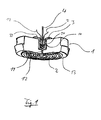
- the in Fig. 1 shown pressure transmitter comprises a base body 1, which preferably has a substantially cylindrically symmetrical structure. At the end face 13 of the body, a separation membrane 2 is attached with its edge 21, so that between the separation membrane 2 and the base body, a pressure chamber 11 is formed.
- the end face 13 of the main body 1 can be seen in the usual way with a membrane bed, against which the separation membrane 2 is pressed in case of overload.
- the pressure chamber 11 has an opening 12 for transmitting the pressure prevailing in the pressure chamber.
- the opening 12 is preferably formed as a capillary.
- the opening 12 extends as far as a pressure line connection 14, which is preferably designed as a substantially cylindrical or axially symmetrical recess in the end face of the base body 1 facing away from the separation membrane 2.
- connection of the pressure supply line 4 takes place in the preferred embodiment by means of a connection adapter 3, in which the sensor for monitoring a material property of the transmission medium is integrated. Details of the terminal adapter 3 will now be described with additional reference Fig. 2 described. The proportions of individual elements of in Fig. 2 shown embodiment of a connection adapter differ from those of the configuration of the connection adapter in Fig. 1 , In both drawings, however, identical reference numerals are used for corresponding elements.
- connection adapter 3 comprises a pressure medium connection 37 complementary to the line connection 14 and a pressure line receptacle which is formed in a preferably cylindrical first section 33.
- the connection adapter 3 also comprises a first electrode 31 and a second electrode 32 of the sensor.
- the Druckmiftleranschluß 37 may for example comprise a substantially cylindrical or conical projection which extends in the axial direction from an end face of the first portion 33 and has a channel 36 through which a flow connection between the pressure chamber opening 12 of the pressure transmitter 1 and the pressure line receiving is effected.
- the end face of the first portion outside the cylindrical protrusion serves as an axial abutment surface defining the position of the connection adapter 3 with respect to the base body 1 and at the same time a (possibly additional) seal between the base body 1 and the connection adapter 3 causes.
- the lateral surface 38 of the substantially cylindrical projection may optionally be provided with an external thread, which is complementary to an internal thread in the wall of the pressure line connection 14.
- the pressure line intake for example, have a chamber 35 in the connection adapter 3, in which the pressure supply line 4 opens.
- the sensor for monitoring a material property of the second medium in this case the electrical conductivity, is likewise arranged in the pressure line receptacle.
- the first electrode 31 and the second electrode 32 of the sensor may, for example, be fixed in an opening of the chamber 35 by means of a glass feedthrough 34.
- the pressure feed line is also by means of a glass feedthrough, fastened, in particular the same glass feedthrough 34 can be used.
- the chamber 35 should be sufficiently large so that the electrodes can be securely positioned isolated from one another, and so that a suitable space filled with the second medium or a transfer liquid extends between the electrodes.
- the transport of impurities into the environment of the electrodes should be as fast as possible. Therefore, as short as possible and direct paths should be given with large cross-sections between the channel 36 in the diaphragm seal connection 37 and the electrodes. Insofar as the channel 36 is also a portion of the path of contamination, the channel 36 should also have the lowest possible diffusion resistance.
- the total volume of the transfer fluid in the system is to be kept as low as possible in order to minimize the influence of temperature fluctuations on the overall system.
- only one electrode may be provided to measure the conductivity between it and the main body or the chamber.
- Pressure supply line 4 is preferably designed as a capillary line.
- the capillary is tubular, but it can also as a hole in a solid block, for example a Separator, be formed, in which the sensor and the pressure connection adapter or a pressure transmitter connection can be integrated.
- the pressure feed line transfers the pressure present in the second medium to a pressure measuring cell, not specified, which generates a pressure-dependent electrical signal.
- the electrodes 31, 32 of the conductivity sensor are connected to a suitable evaluation circuit, which monitors the conductivity of the transmission medium.
- the monitoring can be carried out, for example, continuously, periodically or event-controlled, for example on query by a microprocessor.
- the diaphragm seal according to the invention can in principle also have other sensors. Also suitable are u.a. Capacitive sensors, pH sensors, photometers or specific adsorption sensors, which detect the presence of a selected foreign substance from the first medium or the process medium in the transmission medium.
Abstract
Description
Die Erfindung bezieht sich auf einen Druckmittler zur Übertragung eines Drucks von einem in einem ersten Medium vorherrschenden Druck auf ein zweites Medium.The invention relates to a pressure transmitter for transmitting a pressure from a prevailing in a first medium pressure on a second medium.
Genauer betrifft die Erfindung Druckmittler mit
- einem Grundkörper;
- einer Trennmembran, die mit ihrem Rand an dem Grundkörper befestigt ist, wobei die Trennmembran mit ihrer ersten, dem Grundkörper abgewandten Oberfläche mit dem ersten Medium in Kontakt gebracht werden kann, und mit ihrer zweiten, dem Grundkörper zugewandten Oberfläche und dem Grundkörper eine Druckkammer bildet, die mit dem zweiten Medium befüllbar ist, wobei die Druckkammer eine Druckkammeröffnung aufweist, durch welche der Druck mittels des zweiten Mediums übertragen werden kann; und
- einem Sensor, zur Überwachung einer Eigenschaft eines in der Kammer enthaltenen Mediums.
- a basic body;
- a separation membrane which is fastened with its edge to the base body, wherein the separation membrane can be brought into contact with the first medium facing away from the base surface with the first medium, and forms a pressure chamber with its second, the base body facing surface and the base body, which is fillable with the second medium, wherein the pressure chamber has a pressure chamber opening through which the pressure can be transmitted by means of the second medium; and
- a sensor for monitoring a property of a medium contained in the chamber.
Die gattungsgemäßen Druckmittler werden unter anderem bei der Druckmessung in aggressiven Medien eingesetzt, wobei die Trennmembran mit einem aggressiven ersten Medium beaufschlagt wird und den im ersten Medium vorherrschenden Druck auf ein zweites Medium in der Druckkammer überträgt, von wo er über eine geeignete Druckzuleitung einer Druckmeßzelle zugeführt wird. Eine Druckübertragung mit einem Druckmittler und einer angeschlossenen Druckleitung kann aber auch bei nicht aggressiven Medien erwünscht sein, um große Strecken zwischen dem ersten Medium und dem Ort des Druckmeßzelle zu überbrücken.The generic diaphragm seal are used inter alia in the pressure measurement in aggressive media, the separation membrane is acted upon by an aggressive first medium and the prevailing pressure in the first medium to a second medium in the pressure chamber transfers, from where it fed via a suitable pressure supply to a pressure measuring cell becomes. However, a pressure transmission with a pressure transmitter and a connected pressure line may also be desirable in non-aggressive media to bridge long distances between the first medium and the location of the pressure measuring cell.
Zur Druckübertragung werden als zweites Medium vorzugsweise inkompressible Öle verwendet. Insofern als ein solches Medium geeignet ist, ein Meßmedium zu kontaminieren, und aus verschiedenen anderen Gründen ist es erforderlich, ein Leck in der Trennmembran oder einen Bruch der Trennmembran frühzeitig zu erkennen. Hierzu offenbart Bastiaan in der Europäische Patentanmeldung
Für die unterschiedlichen Druckmeßanwendungen gibt es eine unübersehbare Vielfalt an Druckmittlern, die den jeweiligen Anforderungen angepaßt sind. Es erfordert einen sehr hohen Fertigungsaufwand, diese Vielfalt von Sensoren mit der von Bastiaan vorgeschlagenen Leitfähigkeitssonde auszustatten. Zudem erfordert die Anordnung nach Bastiaan einen Mindestdurchmesser von 1,5 Zoll bzw. 3,8 cm, um den Leitfähigkeitssensor neben der Druckzuleitung anzuordnen, wie aus einer dem Gegenstand der Anmeldung entsprechenden Produktbeschreibung "Badoterm's MDS Diaphragm Leakage Detection System" der Anmelderin hervorgeht. Die genannte Einschränkung ist für viele Anwendungen inakzeptabel.For the different pressure measuring applications, there is an unmistakable variety of diaphragm seals, which are adapted to the respective requirements. It takes a very high manufacturing effort to equip this variety of sensors with the proposed by Bastiaan conductivity probe. In addition, Bastiaan's arrangement requires a minimum diameter of 1.5 inches and 3.8 cm, respectively, to place the conductivity sensor adjacent to the pressure feed line, as evidenced by Applicant's product description "Badoterm's MDS Diaphragm Leakage Detection System". The above limitation is unacceptable for many applications.
Zudem erfolgt der Transport der Verunreinigungen zum Sensor beim beschriebenen Druckmittler rein diffusiv. Dies kann je nach Tiefe des Sacklochs und je nach Einbaubedingungen des Druckmittlers zu einer großen Zeitverzögerung zwischen dem Auftreten eines Lecks und dem Nachweis der daraus resultierenden Verunreinigung führen.In addition, the transport of impurities to the sensor in the described diaphragm seal is purely diffusive. Depending on the depth of the blind hole and the installation conditions of the diaphragm seal, this can lead to a large time delay between the occurrence of a leak and the detection of the resulting contamination.
Die Offenlegungsschrift
Es ist daher die Aufgabe der vorliegenden Erfindung einen verbesserten Druckmittler vorzuschlagen, der die Nachteile des Stands der Technik überwindet.It is therefore the object of the present invention to propose an improved pressure transmitter, which overcomes the disadvantages of the prior art.
Erfindungsgemäß wird die Aufgabe gelöst durch die Vorrichtungen gemäß dem unabhängigen Anspruch 1. Weitere Vorteile und Gesichtspunkte ergeben sich aus den abhängigen Ansprüchen der Beschreibung und den Zeichnungen.According to the invention the object is achieved by the devices according to the
Die erfindungsgemäße Vorrichtung zur Übertragung eines Drucks von einem in einem ersten Medium vorherrschenden Druck mittels eines zweiten Mediums auf eine Druckmesszelle, umfasst
einen Grundkörper; eine Treinnmembran, die mit ihrem Rand an dem Grundkörper befestigt ist,
wobei die Trennmembran mit ihrer ersten, dem Grundkörper abgewandten Oberfläche mit dem ersten Medium in Kontakt gebracht werden kann, und mit ihrer zweiten, dem Grundkörper zugewandten Oberfläche und dem Grundkörper eine Druckkammer bildet, die mit dem zweiten Medium befüllbar ist,
wobei die Druckkammer eine Druckkammeröfmung aufweist, eine Druckzuleitung, die über die Druckkammeröfinung mit der Druckkammer in Fließverbindung steht,
wobei der Druck durch die Druckzuleitung mittels des zweiten Mediums zu einer Druckmesszelle zu übertragen ist; und einen Sensor, zur Überwachung einer Materialeigenschaft des zweiten Mediums,
dadurch gekennzeichnet,
dass der Sensor über die Druckkammeröffnung mit der Druckkammer in Fließverbindung steht.The inventive device for transmitting a pressure from a prevailing in a first medium pressure by means of a second medium to a pressure measuring cell comprises
a main body; a trefoil membrane, which is fastened with its edge to the main body,
wherein the separation membrane can be brought into contact with the first medium with its first surface facing away from the base body, and with its second surface facing towards the base body and the base body forms a pressure chamber which can be filled with the second medium,
the pressure chamber having a Druckkammeröfmung, a pressure supply line, which is in fluid communication with the pressure chamber via the Druckkammeröfinung,
wherein the pressure is to be transmitted by the pressure supply line by means of the second medium to a pressure measuring cell; and a sensor for monitoring a material property of the second medium,
characterized,
the sensor is in fluid communication with the pressure chamber via the pressure chamber opening.
Vorzugsweise ist der Sensor ein Leitfähigkeitssensor. Weiterhin kann der Sensor ein kapazitiver Sensor sein, der die relative Dielektrizitätskonstante des zweiten Mediums überwacht.Preferably, the sensor is a conductivity sensor. Furthermore, the sensor may be a capacitive sensor that monitors the relative dielectric constant of the second medium.
Nach dem Auftreten eines Lecks in der Trennmembran werden die Materialeigenschaften des zweiten Mediums durch Verunreinigungen aus dem ersten Medium verändert. Insofern als die Verunreinigungen sich zumindest bei konstanter Temperatur und konstantem Druck im wesentlichen diffusiv ausbreiten, sollte der Sensor bevorzugt höchstens so weit von der Trennmembran entfernt sein, daß die zu erwartende Diffusionszeit der Verunreinigungen von einem Leck in der Membran zum Sensor eine vorgegebene Zeitspanne nicht überschreitet. Je nach Erfordernis, weiches im wesentlichen durch das Einsatzgebiet des Sensors vorgegeben ist, kann dieses Zeitintervall im Bereich von Minuten, Stunden, Tagen oder Wochen liegen. Um den erfindungsgemäßen Druckmittler möglichst universell einsetzen zu können, sollte das Sensorelement mit möglichst geringem Abstand zur Trennmembran angeordnet sein.After the occurrence of a leak in the separation membrane, the material properties of the second medium are changed by impurities from the first medium. Insofar as the contaminants propagate substantially diffusely at least at constant temperature and pressure, the sensor should preferably be at most far enough away from the separation membrane that the expected diffusion time of the contaminants from a leak in the membrane to the sensor does not exceed a predetermined period of time , Depending on the requirement, which is essentially predetermined by the field of application of the sensor, this time interval can be in the range of minutes, hours, days or weeks. In order to use the diaphragm seal according to the invention as universally as possible, the sensor element should be arranged with the smallest possible distance to the separation membrane.
Wenn der Sensor ein Leitfähigkeitssensor ist, umfaßt er mindestens zwei voneinander beabstandete Elektroden, wobei der Raum zwischen den Elektroden zumindest teilweise mit dem zweiten Medium gefüllt ist. Der Sensor kann beispielsweise eine erste und eine zweite Elektrode aufweisen, die jeweils voneinander und gegenüber dem Grundkörper bzw. einer Druckzuleitung elektrisch isoliert sind, oder der Sensor kann eine erste Elektrode aufweisen, die gegenüber dem Grundkörper bzw. einer Druckzuleitung isoliert ist, wobei der Grundkörper bzw. die Druckzuleitung als Gegenelektrode dient. Ein kapazitiver Sensor kann die gleiche Anordnung der Elektroden wie ein Leitfähigkeitssensor aufweisen.When the sensor is a conductivity sensor, it comprises at least two spaced-apart electrodes, the space between the electrodes being at least partially filled with the second medium. The sensor may comprise, for example, a first and a second electrode which are each electrically insulated from each other and with respect to the main body or a pressure supply line, or the sensor may comprise a first electrode which is isolated from the main body or a pressure supply line, wherein the main body or the pressure supply line serves as a counter electrode. A capacitive sensor may have the same arrangement of electrodes as a conductivity sensor.
In einer bevorzugten Ausführungsform umfaßt der Grundkörper des Druckmittlers einen Leitungsanschluß zur Verbindung mit einer Druckzuleitung, mittels derer der Druck zu einem Druckwandler übertragen wird. Die Druckkammeröffnung mündet in diesem Leitungsanschluß. Der Sensor kann nun beispielsweise in dem Leitungsanschluß oder in einem Anschlußadapter angeordnet sein, mit dem die Druckzuleitung an den Leitungsanschluß angeschlossen wird.In a preferred embodiment, the main body of the pressure transmitter comprises a line connection for connection to a pressure supply line, by means of which the pressure is transmitted to a pressure transducer. The pressure chamber opening opens into this line connection. The sensor can now be arranged, for example, in the line connection or in a connection adapter with which the pressure supply line is connected to the line connection.
Das Anschlußadapter umfaßt einen Druckmittleranschluß, welcher komplementär ist zu dem dem Leitungsanschluß, und eine Druckleitungsaufnahme. Das Anschlußadapter umfaßt zudem eine erste Elektrode und eine zweite Elektrode des Sensors. Die Druckleitungsaufnahme kann beispielsweise eine Kammer in dem Anschlußadapter aufweisen, in welcher die Druckzuleitung mündet. Die erste Elektrode und die zweite Elektrode können beispielsweise mittels einer Glasdurchführung in einer Öffnung der Kammer befestigt sein. Besonders bevorzugt ist die Druckzuleitung ebenfalls mittels einer Glasdurchführung, insbesondere der gleichen Glasdurchführung, befestigt.The terminal adapter comprises a diaphragm seal connection, which is complementary to the line connection, and a pressure line receiving. The terminal adapter also includes a first electrode and a second electrode of the sensor. The pressure line intake, for example, have a chamber in the connection adapter, in which the pressure supply line opens. The first electrode and the second electrode may be fixed, for example by means of a glass feedthrough in an opening of the chamber. Particularly preferably, the pressure feed line is also fastened by means of a glass feedthrough, in particular the same glass feedthrough.
Die Anordnung des Sensors zur Überwachung einer Materialeigenschaft des Übertragungsmediums in der Druckkammeröffnung oder in einem anderen mit der Druckkammer über die Druckkammeröffnung kommunizierenden Abschnitt hat weiterhin den Vorteil, daß es auch zu einem Transport der Verunreinigungen durch Konvektion bzw. durch Fluß des Übertragungsmediums kommt.The arrangement of the sensor for monitoring a material property of the transfer medium in the pressure chamber opening or in another communicating with the pressure chamber via the pressure chamber opening portion has the further advantage that it also comes to a transport of contaminants by convection or by flow of the transfer medium.
Dies sollte häufig eine schnellere Nachweisbarkeit der Verunreinigungen bewirken als der rein diffusive Transport der Verunreinigungen, wie er bei der Anordnung gemäß Bastiaan auftritt. Geht man beispielsweise von einem Arbeitsvolumen der Druckkammer von 100 mm3 und einem Öffnungsdurchmesser von 1 mm aus, aus, so bedeutet eine Verdrängung des gesamten Arbeitsvolumens bei einem Überlastdruckschlag eine Verschiebung des Übertragungsmediums in der Öffnung um etwa 127 mm. Auf diese Weise können die Verunreinigungen mit dem Übertragungsmedium erheblich schneller zum Sensor gelangen, als dies mit der Anordnung gemäß Bastiaan der Fall ist.This should often cause a faster detection of impurities than the purely diffusive transport of impurities, as it occurs in the arrangement according to Bastiaan. If one assumes, for example, a working volume of the pressure chamber of 100 mm 3 and an opening diameter of 1 mm, then a displacement of the entire working volume in the event of an overload pressure impact means a displacement of the transmission medium in the opening by about 127 mm. In this way, the contamination with the transmission medium can reach the sensor much faster than is the case with the arrangement according to Bastiaan.
Gleichermaßen können Temperaturschwankungen zu einem konvektiven Transport der Verunreinigungen führen. Eine Temperaturänderung in der Druckzuleitung von beispielsweise 10°C führt bei einem Volumenausdehnungskoeffizienten von etwa 10-3/K bei einer Druckzuleitungslänge von 10 m und einem Innendurchmesser von 1 mm zu einer Volumenänderung von etwa 80 mm3, was einer Verschiebung der Flüssigkeitssäule von etwa 100 mm am Ende der Druckzuleitung entspricht. Der beschriebene konvektive Transport zu dem Sensor ist um so effektiver, je größer die Länge der Druckzuleitung im Verhältnis zum Abstand des Sensors von der Trennmembran ist.Similarly, temperature variations can lead to convective transport of the contaminants. A temperature change in the pressure feed line, for example, 10 ° C leads at a volume expansion coefficient of about 10 -3 / K at a pressure feed length of 10 m and an inner diameter of 1 mm to a volume change of about 80 mm 3 , which is a shift of the liquid column of about 100 mm at the end of the pressure line. The described convective transport to the sensor is all the more effective, the greater the length of the pressure feed line in relation to the distance of the sensor from the separation membrane.
Zur optimalen Ausnutzung dieses Effekts sollten die Elemente des Sensors, beispielsweise die Elektroden eines Leitfähigkeitssensors möglichst in einem Bereich der Druckkammeröffnung, der Druckzuleitung, oder eines Anschlußadapters zwischen Druckmittler und Druckzuleitung angeordnet sein, der von dem beschriebenen Konvektionsstrom durchströmt wird oder unmittelbar an einen solchen Bereich angrenzt.For optimum utilization of this effect, the elements of the sensor, for example, the electrodes of a conductivity sensor should be arranged as possible in a region of the pressure chamber opening, the pressure supply line, or a connection adapter between pressure transmitter and pressure supply, which is flowed through by the described convection or immediately adjacent to such a region ,
Die Erfindung wird anhand der nachfolgenden Zeichnungen näher erläutert. Es zeigt:
-
Fig. 1 : Eine perspektivische Schnittzeichnung eine bevorzugte Ausführungsform eines erfindungsgemäßen Druckmittlers. -
Fig. 2 : Eine bevorzugte Ausführungsform eines erfindungsgemäßen Anschlußadapters.
-
Fig. 1 A perspective sectional view of a preferred embodiment of a pressure transmitter according to the invention. -
Fig. 2 : A preferred embodiment of a connection adapter according to the invention.
Der in
Die Druckkammer 11 weist eine Öffnung 12 zur Übertragung des in der Druckkammer vorherrschenden Drucks auf. Die Öffnung 12 ist bevorzugt als Kapillarleitung ausgebildet.
Die Öffnung 12 erstreckt sich bei der bevorzugten Ausführungsform bis zu einem Druckleitungsanschluß 14, der vorzugsweise als im wesentlichen zylindrische bzw. axialsymmetrische Vertiefung in der von der Trennmembran 2 abgewandten Stirnfläche des Grundkörpers 1 ausgebildet ist.The
In the preferred embodiment, the
Der Anschluß der Druckzuleitung 4 erfolgt bei der bevorzugten Ausführungsform mittels eines Anschlußadapters 3, in welches der Sensor zur Überwachung einer Materialeigenschaft des Übertragungsmediums integriert ist. Einzelheiten des Anschlußadapters 3 werden nun unter zusätzlicher Bezugnahme auf
Das Anschlußadapter 3 umfaßt einen zu dem Leitungsanschluß 14 komplementären Druckmittleranschluß 37 und eine Druckleitungsaufnahme, die in einem vorzugsweise zylindrischen, ersten Abschnitt 33 ausgebildet ist. Das Anschlußadapter 3 umfaßt zudem eine erste Elektrode 31 und eine zweite Elektrode 32 des Sensors.The connection adapter 3 comprises a pressure medium connection 37 complementary to the
Der Druckmiftleranschluß 37 kann beispielsweise einen im wesentlichen zylindrischen oder konischen Vorsprung umfassen, welcher sich in axialer Richtung von einer Sirnfläche des ersten Abschnitts 33 erstreckt und einen Kanal 36 aufweist, durch den eine Fließverbindung zwischen der Druckkammeröffnung 12 des Druckmittlers 1 und der Druckleitungsaufnahme bewirkt wird.The Druckmiftleranschluß 37 may for example comprise a substantially cylindrical or conical projection which extends in the axial direction from an end face of the
Insofern, als der zylindrische Vorsprung einen kleineren Radius aufweist als der erste Abschnitt 33, dient die Stirnfläche des ersten Abschnitts außerhalb des zylindrischen Vorsprungs als axiale Anschlagfläche, welche die Position des Anschlußadapters 3 bezüglich des Grundkörpers 1 definiert und zugleich eine (ggf. zusätzliche) Abdichtung zwischen dem Grundkörper 1 und dem Anschlußadapter 3 bewirkt.Inasmuch as the cylindrical protrusion has a smaller radius than the
Die Mantelfläche 38 des im wesentlichen zylindrischen Vorsprungs kann ggf. mit einem Außengewinde versehen sein, welches zu einem Innengewinde in der Wandung des Druckleitungsanschluß 14 komplementär ist.The
Die Druckleitungsaufnahme kann beispielsweise eine Kammer 35 in dem Anschlußadapter 3 aufweisen, in welcher die Druckzuleitung 4 mündet. Der Sensor zur Überwachung einer Materialeigenschaft des zweiten Mediums, hier der elektrischen Leitfähigkeit, ist ebenfalls in der Druckleitungsaufnahme angeordnet. Die erste Elektrode 31 und die zweite Elektrode 32 des Sensors können beispielsweise mittels einer Glasdurchführung 34 in einer Öffnung der Kammer 35 befestigt sein. Vorzugsweise ist die Druckzuleitung ebenfalls mittels einer Glasdurchführung, befestig, wobei insbesondere die gleiche Glasdurchführung 34 verwendet werden kann. Gleichermaßen ist es möglich, die beiden Elektroden bzw. die Druckzuleitung jeweils in einer separaten Öffnung mittels einer Glasdurchführung oder einem anderen geeigneten Befestigungsmittel zu befestigen.The pressure line intake, for example, have a
Die Kammer 35 sollte einerseits hinreichend groß sein, damit die Elektroden sicher voneinander isoliert positioniert sein können, und damit sich zwischen den Elektroden ein geeigneter mit dem zweiten Medium bzw. einer Übertragungsflüssigkeit erfüllter Raum erstreckt. Zudem sollte der Transport von Verunreinigungen in die Umgebung der Elektroden möglichst schnell erfolgen. Deshalb sollten möglichst kurze und direkte Pfade mit großen Querschnitten zwischen dem Kanal 36 im Druckmittleranschluß 37 und den Elektroden gegeben sein. Insofern als der Kanal 36 ebenfalls ein Abschnitt des Pfades von Verunreinigungen ist, sollte auch der Kanal 36 einen möglichst geringen Diffusionswiderstand aufweisen. Andererseits ist das Gesamtvolumen der Übertragungsflüssigkeit im System möglichst gering zu halten, um den Einfluß von Temperaturschwankungen auf das Gesamtsystem zu minimieren.On the one hand, the
Anstelle von zwei separaten Elektroden kann auch nur eine Elektrode vorgesehen sein, um die Leitfähigkeit zwischen dieser und dem Grundkörper bzw. der Kammer zu messen.Instead of two separate electrodes, only one electrode may be provided to measure the conductivity between it and the main body or the chamber.
Druckzuleitung 4 ist vorzugsweise als Kapillarleitung ausgebildet. In der dargestellten Ausführungsform ist die Kapillarleitung röhrenförmig ausgebildet, sie kann jedoch auch als Bohrung in einem massiven Block, beispielsweise einem Trennkörper, ausgebildet sein, in den der Sensor und das Druckanschlußadapter oder ein Druckmittleranschluß integriert sein kann.
Die Druckzuleitung überträgt den im zweiten Medium vorhanden Druck zu einer nicht näher bezeichneten Druckmeßzelle, die ein druckabhängiges elektrisches Signal erzeugt.The pressure feed line transfers the pressure present in the second medium to a pressure measuring cell, not specified, which generates a pressure-dependent electrical signal.
Die Elektroden 31, 32 des Leitfähigkeitssensors sind mit einer geeigneten Auswertungsschaltung verbunden, welche die Leitfähigkeit des Übertragungsmediums überwacht. Die Überwachung kann beispielsweise kontinuierlich, periodisch oder ereignisgesteuert, beispielsweise auf Abfrage durch einen Mikroprozessor erfolgen.The
Wenngleich derzeit Leitfähigkeitssensoren bevorzugte Sensoren zur Überwachung einer Materialeigenschaft des Übertragungsmediums sind, können die erfindungsgemäßen Druckmittler grundsätzliche auch andere Sensoren aufweisen. Geeignet sind weiterhin u.a. kapazitive Sensoren, pH-Sensoren, Photometer oder spezifische Adsorptionssensoren, welche die Anwesenheit einer ausgewählten Fremdsubstanz aus dem ersten Medium bzw. dem Prozeßmedium im Übertragungsmedium nachweisen.Although currently conductivity sensors are preferred sensors for monitoring a material property of the transmission medium, the diaphragm seal according to the invention can in principle also have other sensors. Also suitable are u.a. Capacitive sensors, pH sensors, photometers or specific adsorption sensors, which detect the presence of a selected foreign substance from the first medium or the process medium in the transmission medium.
Claims (8)
- Unit for transferring a pressure present in a first medium to a pressure measuring cell with the aid of a second medium, comprising:- a meter body (1);- a process isolating diaphragm (2) whose edge is attached to the meter body (1), whereby the process isolating diaphragm (1) can be brought into contact with the first medium with its first surface, which faces away from the meter body (1), and forms a pressure chamber (11) with the meter body (1) and its second surface, which faces towards the meter body (1). Said chamber can be filled with the second medium whereby the pressure chamber (11) exhibits a pressure chamber opening (12);- a pressure supply line which forms a flow connection with the pressure chamber via the pressure chamber opening, whereby the pressure is to be transmitted to a pressure measuring cell through the pressure supply line with the aid of the second medium;- a sensor that monitors a material property of the second medium, whereby the sensor forms a flow connection with the pressure chamber (11) via the pressure chamber opening (12).
- Unit as per Claim 1, where the sensor is a conductivity sensor.
- Unit as per Claim 2, whereby the conductivity sensor exhibits a first electrode (31) and a second electrode (32), which are arranged isolated from one another and from the meter body (1).
- Unit as per Claim 2, whereby the conductivity sensor exhibits an electrode which is arranged isolated from the meter body (1) to measure the conductivity of the second medium between the electrode and the meter body or with a component connected to the meter body such that a conductive connection takes place.
- Unit as per Claim 3, where the pressure supply line (4) is a capillary tube.
- Unit as per Claim 3 or 4 further comprising a connecting adapter (3) which connects the pressure supply line (4) to the pressure chamber opening.
- Unit as per Claim 6, where the connecting adapter (3) comprises the sensor.
- Unit as per one of the previous claims, whereby variable exposure of the process isolating diaphragm to pressure and/or a change in the volume of the second medium on account of temperature fluctuations within a predefined operating range of the unit causes the second medium to flow through the pressure chamber opening, whereby the sensor is arranged at such a distance from the pressure chamber that at least some of the medium in the pressure chamber at 50% of the nominal pressure and at the average temperature of the temperature measuring range of the unit flows as far as the position of the sensor, in the event of a compression in the pressure chamber, by not more than 30%, preferably by not more than 20% and particularly preferably by not more than 10%.
Applications Claiming Priority (3)
| Application Number | Priority Date | Filing Date | Title |
|---|---|---|---|
| DE10131855 | 2001-06-30 | ||
| DE10131855A DE10131855A1 (en) | 2001-06-30 | 2001-06-30 | Diaphragm seal with device for detecting membrane breaks and connection adapter with device for detecting membrane breaks |
| PCT/EP2002/006613 WO2003004984A1 (en) | 2001-06-30 | 2002-06-15 | Pressure transmission system comprising a device for identifying membrane ruptures and connection adapter comprising a device for identifying membrane ruptures |
Publications (2)
| Publication Number | Publication Date |
|---|---|
| EP1402241A1 EP1402241A1 (en) | 2004-03-31 |
| EP1402241B1 true EP1402241B1 (en) | 2010-01-06 |
Family
ID=7690224
Family Applications (1)
| Application Number | Title | Priority Date | Filing Date |
|---|---|---|---|
| EP02743209A Expired - Lifetime EP1402241B1 (en) | 2001-06-30 | 2002-06-15 | Pressure transmission system comprising a device for identifying membrane ruptures |
Country Status (8)
| Country | Link |
|---|---|
| US (1) | US7197935B2 (en) |
| EP (1) | EP1402241B1 (en) |
| JP (1) | JP3926327B2 (en) |
| CN (1) | CN1268905C (en) |
| AT (1) | ATE454616T1 (en) |
| DE (2) | DE10131855A1 (en) |
| RU (1) | RU2265812C2 (en) |
| WO (1) | WO2003004984A1 (en) |
Cited By (1)
| Publication number | Priority date | Publication date | Assignee | Title |
|---|---|---|---|---|
| DE102014118616A1 (en) * | 2014-12-15 | 2016-06-16 | Endress + Hauser Gmbh + Co. Kg | pressure transducers |
Families Citing this family (9)
| Publication number | Priority date | Publication date | Assignee | Title |
|---|---|---|---|---|
| DE20311320U1 (en) * | 2003-07-22 | 2003-10-09 | Endress & Hauser Gmbh & Co Kg | Dynamic diaphragm seal |
| JP4709585B2 (en) * | 2005-06-09 | 2011-06-22 | トリニティ工業株式会社 | Coating material filling method and apparatus |
| DE102005055285A1 (en) * | 2005-11-17 | 2007-05-24 | Endress + Hauser Gmbh + Co. Kg | Process medium`s pressure measuring transducer, has hydraulic exciter communicating with hydraulic path that impresses pressure variations, and control provided for driving hydraulic exciter |
| DE102007040864A1 (en) * | 2007-08-29 | 2009-01-02 | Tyco Electronics Amp Gmbh | Method and device for testing an electrical connection device with respect to tightness |
| DE102011100532A1 (en) | 2011-05-05 | 2012-11-08 | Hydac Technology Gmbh | Medium separating device, in particular hydraulic accumulator including associated measuring device and measuring method |
| EP4042123A1 (en) * | 2019-10-10 | 2022-08-17 | Endress+Hauser SE+Co. KG | Pressure gauge for measuring a pressure |
| DE102019127315A1 (en) * | 2019-10-10 | 2021-04-15 | Endress+Hauser SE+Co. KG | Pressure measuring device for measuring a pressure |
| US20210123198A1 (en) * | 2019-10-24 | 2021-04-29 | David Kenneth Winstanley | Expendable shock absorber |
| US11609141B2 (en) * | 2021-06-01 | 2023-03-21 | Schneider Electric Systems Usa, Inc. | Condition detection of pressure transmitter diaphragm |
Citations (1)
| Publication number | Priority date | Publication date | Assignee | Title |
|---|---|---|---|---|
| DE4235684A1 (en) * | 1992-10-22 | 1994-04-28 | Pokorny Gmbh | Arrangement for attaching a pressure measuring device to a fluid container or a fluid line |
Family Cites Families (5)
| Publication number | Priority date | Publication date | Assignee | Title |
|---|---|---|---|---|
| DE3941369A1 (en) | 1989-10-12 | 1991-04-25 | Armin Claasnitz | Transfer device for pressure measuring-processing system - has switch and signalling arrangement for immediate detection of membrane damage |
| US5072190A (en) * | 1990-08-14 | 1991-12-10 | The Foxboro Company | Pressure sensing device having fill fluid contamination detector |
| WO1996017235A1 (en) * | 1994-11-30 | 1996-06-06 | Rosemount Inc. | Pressure transmitter with fill fluid loss detection |
| NL1004330C2 (en) * | 1996-10-22 | 1998-04-24 | Badotherm International B V | Leak detection. |
| DE19949831B4 (en) * | 1999-10-15 | 2007-08-02 | Wika Alexander Wiegand Gmbh & Co | Diaphragm seals |
-
2001
- 2001-06-30 DE DE10131855A patent/DE10131855A1/en not_active Withdrawn
-
2002
- 2002-06-15 US US10/481,418 patent/US7197935B2/en not_active Expired - Lifetime
- 2002-06-15 EP EP02743209A patent/EP1402241B1/en not_active Expired - Lifetime
- 2002-06-15 AT AT02743209T patent/ATE454616T1/en not_active IP Right Cessation
- 2002-06-15 JP JP2003510911A patent/JP3926327B2/en not_active Expired - Fee Related
- 2002-06-15 DE DE50214148T patent/DE50214148D1/en not_active Expired - Lifetime
- 2002-06-15 RU RU2004102684/28A patent/RU2265812C2/en not_active IP Right Cessation
- 2002-06-15 WO PCT/EP2002/006613 patent/WO2003004984A1/en active Application Filing
- 2002-06-15 CN CNB028133390A patent/CN1268905C/en not_active Expired - Fee Related
Patent Citations (1)
| Publication number | Priority date | Publication date | Assignee | Title |
|---|---|---|---|---|
| DE4235684A1 (en) * | 1992-10-22 | 1994-04-28 | Pokorny Gmbh | Arrangement for attaching a pressure measuring device to a fluid container or a fluid line |
Cited By (1)
| Publication number | Priority date | Publication date | Assignee | Title |
|---|---|---|---|---|
| DE102014118616A1 (en) * | 2014-12-15 | 2016-06-16 | Endress + Hauser Gmbh + Co. Kg | pressure transducers |
Also Published As
| Publication number | Publication date |
|---|---|
| ATE454616T1 (en) | 2010-01-15 |
| CN1268905C (en) | 2006-08-09 |
| US7197935B2 (en) | 2007-04-03 |
| DE10131855A1 (en) | 2003-01-23 |
| CN1522361A (en) | 2004-08-18 |
| WO2003004984A1 (en) | 2003-01-16 |
| EP1402241A1 (en) | 2004-03-31 |
| RU2004102684A (en) | 2005-04-10 |
| JP3926327B2 (en) | 2007-06-06 |
| US20040244494A1 (en) | 2004-12-09 |
| JP2004533623A (en) | 2004-11-04 |
| DE50214148D1 (en) | 2010-02-25 |
| RU2265812C2 (en) | 2005-12-10 |
Similar Documents
| Publication | Publication Date | Title |
|---|---|---|
| DE102013100889B4 (en) | pressure detector | |
| EP0594808B1 (en) | Device for measuring pressure and pressure differentials with a three part threaded housing and an angle ring | |
| DE102009027581B4 (en) | Measuring device comprising a measuring probe and a fastening device | |
| EP1176419B1 (en) | Measuring probe for potentiometric measurements, method for checking the ageing condition of the probe and the use of it | |
| EP1618362B1 (en) | Temperature-compensated pressure gauge | |
| EP1402241B1 (en) | Pressure transmission system comprising a device for identifying membrane ruptures | |
| DE2052515B2 (en) | Capacitive pressure sensor | |
| DE10200779B4 (en) | Diaphragm seal with membrane breakage detection module and pressure gauge for membrane breakage detection | |
| EP2174106B2 (en) | Force sensor | |
| DE102006040325A1 (en) | Joining section`s tightness monitoring device for differential pressure measuring device, has detection unit detecting condition change of detection medium, and output unit generating indication that leakage is occurred in joining section | |
| EP1399723B1 (en) | Pressure transmitting device with forecasting corrosion monitoring | |
| EP2333508B1 (en) | Pressure transmitter with temperature sensor | |
| DE10232315B4 (en) | Combined temperature and pressure sensor and method for the determination of physical characteristics | |
| EP1275950A2 (en) | Relative pressure measuring device | |
| DE102015105609A1 (en) | Sensor, drive component with sensor, drive with drive component and evaluation method | |
| EP1425563B1 (en) | Pressure measuring apparatus | |
| EP1608941B1 (en) | Pressure sensor with flame arrestor | |
| WO1989007055A1 (en) | Resilient connecting device, in particular with incorporated force-measuring device and process for manufacturing it | |
| DE10133745A1 (en) | Pressure sensor and method for its operation | |
| DE102011111558B4 (en) | Dry transducer | |
| DE3327265A1 (en) | IMPROVED METER FOR MEASURING PRESSURE OF A LIQUID, ESPECIALLY AN AGGRESSIVE AND HOT LIQUID | |
| EP3913347A1 (en) | Measuring device for detecting strain in an elastomeric hose | |
| DE102005045065B4 (en) | Detector device for functional testing of sealing systems | |
| DE102017213894A1 (en) | Measuring device for measuring the pressure of a medium in a container and capacitive pressure measuring cell | |
| EP1098180B1 (en) | Apparatus for detecting an amount of displacement |
Legal Events
| Date | Code | Title | Description |
|---|---|---|---|
| PUAI | Public reference made under article 153(3) epc to a published international application that has entered the european phase |
Free format text: ORIGINAL CODE: 0009012 |
|
| 17P | Request for examination filed |
Effective date: 20031224 |
|
| AK | Designated contracting states |
Kind code of ref document: A1 Designated state(s): AT BE CH CY DE DK ES FI FR GB GR IE IT LI LU MC NL PT SE TR |
|
| AX | Request for extension of the european patent |
Extension state: AL LT LV MK RO SI |
|
| 17Q | First examination report despatched |
Effective date: 20090210 |
|
| GRAP | Despatch of communication of intention to grant a patent |
Free format text: ORIGINAL CODE: EPIDOSNIGR1 |
|
| RTI1 | Title (correction) |
Free format text: PRESSURE TRANSMISSION SYSTEM COMPRISING A DEVICE FOR IDENTIFYING MEMBRANE RUPTURES |
|
| GRAS | Grant fee paid |
Free format text: ORIGINAL CODE: EPIDOSNIGR3 |
|
| GRAA | (expected) grant |
Free format text: ORIGINAL CODE: 0009210 |
|
| AK | Designated contracting states |
Kind code of ref document: B1 Designated state(s): AT BE CH CY DE DK ES FI FR GB GR IE IT LI LU MC NL PT SE TR |
|
| REG | Reference to a national code |
Ref country code: GB Ref legal event code: FG4D Free format text: NOT ENGLISH |
|
| REG | Reference to a national code |
Ref country code: CH Ref legal event code: EP |
|
| REG | Reference to a national code |
Ref country code: IE Ref legal event code: FG4D |
|
| REF | Corresponds to: |
Ref document number: 50214148 Country of ref document: DE Date of ref document: 20100225 Kind code of ref document: P |
|
| REG | Reference to a national code |
Ref country code: NL Ref legal event code: VDEP Effective date: 20100106 |
|
| PG25 | Lapsed in a contracting state [announced via postgrant information from national office to epo] |
Ref country code: PT Free format text: LAPSE BECAUSE OF FAILURE TO SUBMIT A TRANSLATION OF THE DESCRIPTION OR TO PAY THE FEE WITHIN THE PRESCRIBED TIME-LIMIT Effective date: 20100506 Ref country code: NL Free format text: LAPSE BECAUSE OF FAILURE TO SUBMIT A TRANSLATION OF THE DESCRIPTION OR TO PAY THE FEE WITHIN THE PRESCRIBED TIME-LIMIT Effective date: 20100106 Ref country code: ES Free format text: LAPSE BECAUSE OF FAILURE TO SUBMIT A TRANSLATION OF THE DESCRIPTION OR TO PAY THE FEE WITHIN THE PRESCRIBED TIME-LIMIT Effective date: 20100417 |
|
| REG | Reference to a national code |
Ref country code: IE Ref legal event code: FD4D |
|
| PG25 | Lapsed in a contracting state [announced via postgrant information from national office to epo] |
Ref country code: FI Free format text: LAPSE BECAUSE OF FAILURE TO SUBMIT A TRANSLATION OF THE DESCRIPTION OR TO PAY THE FEE WITHIN THE PRESCRIBED TIME-LIMIT Effective date: 20100106 |
|
| PG25 | Lapsed in a contracting state [announced via postgrant information from national office to epo] |
Ref country code: SE Free format text: LAPSE BECAUSE OF FAILURE TO SUBMIT A TRANSLATION OF THE DESCRIPTION OR TO PAY THE FEE WITHIN THE PRESCRIBED TIME-LIMIT Effective date: 20100106 Ref country code: CY Free format text: LAPSE BECAUSE OF FAILURE TO SUBMIT A TRANSLATION OF THE DESCRIPTION OR TO PAY THE FEE WITHIN THE PRESCRIBED TIME-LIMIT Effective date: 20100106 Ref country code: GR Free format text: LAPSE BECAUSE OF FAILURE TO SUBMIT A TRANSLATION OF THE DESCRIPTION OR TO PAY THE FEE WITHIN THE PRESCRIBED TIME-LIMIT Effective date: 20100407 Ref country code: IE Free format text: LAPSE BECAUSE OF FAILURE TO SUBMIT A TRANSLATION OF THE DESCRIPTION OR TO PAY THE FEE WITHIN THE PRESCRIBED TIME-LIMIT Effective date: 20100106 |
|
| PLBE | No opposition filed within time limit |
Free format text: ORIGINAL CODE: 0009261 |
|
| STAA | Information on the status of an ep patent application or granted ep patent |
Free format text: STATUS: NO OPPOSITION FILED WITHIN TIME LIMIT |
|
| 26N | No opposition filed |
Effective date: 20101007 |
|
| BERE | Be: lapsed |
Owner name: ENDRESS + HAUSER G.M.B.H. + CO. KG Effective date: 20100630 |
|
| PG25 | Lapsed in a contracting state [announced via postgrant information from national office to epo] |
Ref country code: DK Free format text: LAPSE BECAUSE OF FAILURE TO SUBMIT A TRANSLATION OF THE DESCRIPTION OR TO PAY THE FEE WITHIN THE PRESCRIBED TIME-LIMIT Effective date: 20100106 Ref country code: MC Free format text: LAPSE BECAUSE OF NON-PAYMENT OF DUE FEES Effective date: 20100630 |
|
| REG | Reference to a national code |
Ref country code: CH Ref legal event code: PL |
|
| GBPC | Gb: european patent ceased through non-payment of renewal fee |
Effective date: 20100615 |
|
| REG | Reference to a national code |
Ref country code: FR Ref legal event code: ST Effective date: 20110228 |
|
| PG25 | Lapsed in a contracting state [announced via postgrant information from national office to epo] |
Ref country code: IT Free format text: LAPSE BECAUSE OF FAILURE TO SUBMIT A TRANSLATION OF THE DESCRIPTION OR TO PAY THE FEE WITHIN THE PRESCRIBED TIME-LIMIT Effective date: 20100106 |
|
| PG25 | Lapsed in a contracting state [announced via postgrant information from national office to epo] |
Ref country code: CH Free format text: LAPSE BECAUSE OF NON-PAYMENT OF DUE FEES Effective date: 20100630 Ref country code: LI Free format text: LAPSE BECAUSE OF NON-PAYMENT OF DUE FEES Effective date: 20100630 |
|
| PG25 | Lapsed in a contracting state [announced via postgrant information from national office to epo] |
Ref country code: FR Free format text: LAPSE BECAUSE OF NON-PAYMENT OF DUE FEES Effective date: 20100630 |
|
| PG25 | Lapsed in a contracting state [announced via postgrant information from national office to epo] |
Ref country code: BE Free format text: LAPSE BECAUSE OF NON-PAYMENT OF DUE FEES Effective date: 20100630 |
|
| PG25 | Lapsed in a contracting state [announced via postgrant information from national office to epo] |
Ref country code: GB Free format text: LAPSE BECAUSE OF NON-PAYMENT OF DUE FEES Effective date: 20100615 |
|
| PG25 | Lapsed in a contracting state [announced via postgrant information from national office to epo] |
Ref country code: AT Free format text: LAPSE BECAUSE OF NON-PAYMENT OF DUE FEES Effective date: 20100615 |
|
| PG25 | Lapsed in a contracting state [announced via postgrant information from national office to epo] |
Ref country code: LU Free format text: LAPSE BECAUSE OF NON-PAYMENT OF DUE FEES Effective date: 20100615 |
|
| PG25 | Lapsed in a contracting state [announced via postgrant information from national office to epo] |
Ref country code: TR Free format text: LAPSE BECAUSE OF FAILURE TO SUBMIT A TRANSLATION OF THE DESCRIPTION OR TO PAY THE FEE WITHIN THE PRESCRIBED TIME-LIMIT Effective date: 20100106 |
|
| PGFP | Annual fee paid to national office [announced via postgrant information from national office to epo] |
Ref country code: DE Payment date: 20150619 Year of fee payment: 14 |
|
| REG | Reference to a national code |
Ref country code: DE Ref legal event code: R119 Ref document number: 50214148 Country of ref document: DE |
|
| PG25 | Lapsed in a contracting state [announced via postgrant information from national office to epo] |
Ref country code: DE Free format text: LAPSE BECAUSE OF NON-PAYMENT OF DUE FEES Effective date: 20170103 |