EP1401721B1 - Korken für behälter - Google Patents
Korken für behälter Download PDFInfo
- Publication number
- EP1401721B1 EP1401721B1 EP02748421A EP02748421A EP1401721B1 EP 1401721 B1 EP1401721 B1 EP 1401721B1 EP 02748421 A EP02748421 A EP 02748421A EP 02748421 A EP02748421 A EP 02748421A EP 1401721 B1 EP1401721 B1 EP 1401721B1
- Authority
- EP
- European Patent Office
- Prior art keywords
- stopper
- film
- face
- cork
- container
- Prior art date
- Legal status (The legal status is an assumption and is not a legal conclusion. Google has not performed a legal analysis and makes no representation as to the accuracy of the status listed.)
- Expired - Lifetime
Links
Images

Classifications
-
- B—PERFORMING OPERATIONS; TRANSPORTING
- B65—CONVEYING; PACKING; STORING; HANDLING THIN OR FILAMENTARY MATERIAL
- B65D—CONTAINERS FOR STORAGE OR TRANSPORT OF ARTICLES OR MATERIALS, e.g. BAGS, BARRELS, BOTTLES, BOXES, CANS, CARTONS, CRATES, DRUMS, JARS, TANKS, HOPPERS, FORWARDING CONTAINERS; ACCESSORIES, CLOSURES, OR FITTINGS THEREFOR; PACKAGING ELEMENTS; PACKAGES
- B65D39/00—Closures arranged within necks or pouring openings or in discharge apertures, e.g. stoppers
- B65D39/0052—Closures arranged within necks or pouring openings or in discharge apertures, e.g. stoppers made in more than one piece
- B65D39/0058—Closures arranged within necks or pouring openings or in discharge apertures, e.g. stoppers made in more than one piece from natural or synthetic cork, e.g. for wine bottles or the like
-
- B—PERFORMING OPERATIONS; TRANSPORTING
- B65—CONVEYING; PACKING; STORING; HANDLING THIN OR FILAMENTARY MATERIAL
- B65D—CONTAINERS FOR STORAGE OR TRANSPORT OF ARTICLES OR MATERIALS, e.g. BAGS, BARRELS, BOTTLES, BOXES, CANS, CARTONS, CRATES, DRUMS, JARS, TANKS, HOPPERS, FORWARDING CONTAINERS; ACCESSORIES, CLOSURES, OR FITTINGS THEREFOR; PACKAGING ELEMENTS; PACKAGES
- B65D2539/00—Details relating to closures arranged within necks or pouring openings or in discharge apertures, e.g. stoppers
- B65D2539/001—Details of closures arranged within necks or pouring opening or in discharge apertures, e.g. stoppers
- B65D2539/008—Details of closures arranged within necks or pouring opening or in discharge apertures, e.g. stoppers with coatings or coverings
Definitions
- the present invention relates to improved stoppers for stoppering openings in containers.
- the present invention relates to improvements to container stoppers that have a film on at least one end to protect the stopper from the contents of the container the stopper is utilised in.
- the stoppers of the invention are particularly useful as stoppers for openings in containers of fluids such as wine.
- the invention also relates to an improved method of producing container stoppers such as the container stoppers of the invention and packaged products, particularly packaged fluid products, in which a stopper of the invention is incorporated.
- cork stoppers have been used in the wine industry for a variety of reasons most of which relate to the exceptional natural qualities of cork as a stopper.
- cork is durable, resilient, free from rotting, is sparingly permeable to gas, is predominantly waterproof, readily compressible and easy to shape. In many respects, therefore, cork is a natural material to consider for sealing fluid in a container such as wine in a wine bottle.
- cork is not the only source of TCA in wine it has been shown that some corks contain levels of TCA which are transferred to wine when stored in bottles. It has also been observed that the taints can be transferred to the wine via the vapour when the bottles are left standing up and the liquid does not contact the cork surface. This is due to corks poor barrier to volatile materials, demonstrated by its readiness to absorb and desorb moisture vapour with changes in relative humidity and its susceptibility to the entry of the volatiles which may be retained and later transferred to wine.
- Another aspect to be considered when packaging products is whether the product needs to be completely sealed off from the environment or whether gaseous exchange is desirable.
- bottle storage of wine consideration of the flavour development of the wine with aging has to be taken into account.
- the concept of bottle aging, bottle maturation or bottle development is well known, however, little is understood or scientifically proven in this area.
- the stopper breathes and that oxygen plays a role in bottle development of the wine, although it is well proven that too much oxygen will oxidise a wine and ruin it.
- Any stopper for use in the wine industry therefore should preferably control the permeability of oxygen and allow in some cases some oxygen to permeate the stopper and come into contact with the wine and in other circumstances significantly block the ingress of oxygen.
- coatings can be used to improve the performance of cork stoppers.
- Waxes and paraffins may be used as coatings and applied to corks to improve the sealing capability, for example. It has been observed that wax coatings also reduce the amount of liquid that soaks into the cork over time.
- Silicone coatings have also been applied to corks to improve the insertion and extraction of the cork. It is thought that the silicone reduces the friction between the cork and the bottle during both the insertion and extraction processes. Coatings of this type are typically applied to the corks while the corks are tumbling in a rotating drum.
- the corks may be tumbled with a solid wax block or a liquid is squirted or otherwise sprayed onto corks.
- the coating is then spread from cork to cork by the physical contact between the corks transferring the coating and evenly distributing it. Heat may also be applied to aid the process.
- FR-983488 discloses a stupper in accordance with the preamble of claim 1.
- the characteristics of the stoppers produced using these techniques has been unsatisfactory. Without wishing to be bound by theory, it is thought that the problem with these approaches is that whilst the stopper is compressible, the coating layer is typically not compressible. This leads to the development of imperfections in the coating layer such as cracking, peeling, creasing and the like.
- Patent application WO 00/34140 purports to overcome these problems and describes a composite stopper with a body and a thick moulded elastomer plug located at the end of the stopper.
- the elastomer plug provides a seal to the bottle and is claimed to be a taint barrier which allegedly prevents the wine touching the cork body of the stopper.
- the difficulty with this approach is that whilst it may overcome the taint problems it creates further problems and/or has a number of disadvantages.
- the unit cost of each stopper is significantly higher than the unit cost of cork stoppers in general and so is undesirable from an economic standpoint.
- elastomer plugs of the type described in this patent have a high transmission rate for oxygen typically meaning that the use of a plug of this type would not be expected to reduce the oxidation of the wine occurring on storage.
- expensive capping machinery is required in order to ensure adequate performance of the stopper once fitted. This markedly slows production of bottled product when these stoppers are used.
- stoppers for containers that overcome or substantially ameliorate the problems associated with contamination of the contents of the container by the materials from which the stopper is made whilst preferably still allowing for control of oxygen transmission through the stopper.
- the present invention provides a container stopper according to claim 1
- a further aspect of the invention is a method according to claim 4.
- a still further aspect of the invention is a packaged product according to claim 5.
- a requirement of a stopper for containers for the mass production of a packaged product is the ability of the stopper to withstand the conditions imposed on the stopper during manufacture of the finished product.
- One of the principle conditions typically imposed upon stoppers irrespective of the industry in which they are utilised is that the stopper is compressed at least partially prior to its insertion into an opening in a container. The stopper then typically expands once the compression force is released leading to a tight fit of the stopper in the container opening. The stopper usually forming an interference fit with the opening in the container.
- In the wine industry bottling operations typically utilise high speed stoppering machines which subject the stoppers to large compression forces.
- the improvements provided for stoppers disclosed in the present invention are applicable to any compressible stopper with a film on at least one end.
- a feature of the stoppers of the present invention is that they have a compressible body. It is preferred that the stopper body is sufficiently compressible so that it can be compressed by at least 5%, more preferably at least 10%, even more preferably at least 15%, even more preferably at least 20%, yet even more preferably at least 30%, even more preferably at least 40%, most preferably at least 50%.
- a number of materials may be used in the construction of the body of the stoppers of the invention to achieve these compressibility parameters.
- any material can be used as long as it meets the compression criteria referred to above with those materials typically utilised in the manufacture of stoppers being suitable.
- Materials that may be used in the construction of the body portion of the stopper comprise cork, agglomerated cork, micro-agglomerated cork, or 1+1 cork.
- the stopper body may be made from a polymeric material.
- the stopper body may comprise medium density or low density, closed cell foamed plastic.
- foam plastics may comprise one or more polymers selected from the group consisting of plastic polymers, inert polymers, homopolymers, copolymers, terpolymers, thermoplastic elastomers, and thermoplastic olefins.
- the closed cell foam plastic material comprises at least one polymer selected from the group consisting of polyethylenes, metallocene catalysed polyethylenes, polybutanes, polybutylenes, polyurethanes, silicones, vinyl based resins, polyesters, ethylenic acrylic copolymers, ethylene-vinyl-acetate copolymers, ethylene-methyl-acrylate copolymers, ethylene-butyl-acrylate copolymers, ethylene-propylene-rubber, styrene butadiene rubber, ethylene-ethyl-acrylic copolymers, ionomers, polypropylenes, copolymers or polyporpylenes and the like. Examples of these types of materials are provided in U.S. patent 6,355,320 .
- the stopper body may also be made of fibres.
- Fibre stopper bodies are disclosed in U.S. 5,665,462 and include vegetable fibres such as cotton, flax, sisal, linen, cellulose and jute, and animal-derived fibres such as angora, wool, alpaca, and mixtures thereof.
- Synthetic fibres can also be used including cellulose acetate, cellulose triacetate, acrylics, aromines (aromatic polyamines), rayons, polyolefins (e.g. polypropylene), nylons, polyesters, polyurethanes, terylenes, teflon and mixtures thereof. Mixtures of the synthetic and/or natural fibres may also be used.
- the gross shape of the stoppers of the invention may vary greatly with the shape of the stopper body typically being determined by the shape of the opening it is intended to be used in.
- the stopper body preferably forms an interference fit with the opening in the container in which it is used, it is preferred that the stopper body has at least one end complementary in shape to the container opening.
- the stopper body may be rectangular, substantially cylindrical, or, indeed, any shape typically found that would be complementary to an opening of a container.
- the stopper body is preferably elongate.
- a feature of the body of the stoppers of the invention is that they have at least one end, preferably two ends. It is this end of the stopper body that is ultimately inserted into the opening in the container and forms the interference fit with the opening, thus providing the stopper performance.
- the most preferred stoppers of the invention are elongate stoppers having a body having two ends, the stopper body being substantially cylindrical. It is preferred that the dimensions of the stopper are such that it is from 30-60 mm in length, more preferably from 35-55 mm in length, even more preferably from 37-47 mm in length, most preferably about 38 mm or about 45 mm in length.
- the stopper body is preferably cylindrical with a diameter of from 18-30 mm, more preferably from 22-26 mm, even more preferably from 23-25 mm, most preferably 24 mm.
- the stoppers of the present invention can be used with any container having an opening which can be sealed with a stopper. It is preferred that the container is a bottle and the stopper is shaped to fit into the opening of the bottle, namely the mouth of the bottle.
- the stoppers of the invention have a film on at least one end of the body which provides a protective layer between the body of the stopper and the contents of the container once the stopper has been inserted into the container opening. If the stopper body only has one end, the film is located on that end. If the stopper body has more than one end, the film may be on only one of the ends or on a number of ends. Thus, where the stopper body has two ends, the film may be on only one end or may be on both ends. If there are two ends it is preferred that the film is on both ends.
- the film only covers the end of the body and does not travel beyond the end of the uncompressed body such as down the sides of the body. It is preferred, therefore, that the film completely covers the end of the uncompressed stopper but does not travel beyond the end of the stopper.
- the improved stoppers in accordance with the invention may utilise a number of different films.
- the film may be a coating layer that has been applied as a liquid and allowed to cure or a coating layer that has been sprayed on or otherwise applied to the stopper body.
- the film may also be a polymeric film.
- the film is a polymeric film, preferably a multilayer polymeric film.
- the polymeric film preferably comprises a barrier layer and an adhesive layer.
- the barrier layer preferably has a low permeability to H 2 O, O 2 and CO 2 and is preferably substantially impermeable to organic molecules with molecular weights greater than 40.
- a number of materials are known that can be used to produce barrier layers for use in the invention stopper.
- the barrier layer comprises one or more polymers or materials selected from the group consisting of polyethylene, polypropylene, polyethylene Terepthalate, ethylene-vinylacetate polymers, polyvinylchloride, polydivinylchloride, polyvinyldichloride, polyvinylacetates, nylon, polyvinyl alcohols, polyurethane, polyacrylonitrile, cellophane, surane, polyamines, polycarbonates, polystyrene, polyalkylene oxides, polyethylene oxides, cellulose, cellulose derivatives, and silicon polymers or metal foils.
- a preferred barrier layer comprises nylon or cellulose, polyethylene and PVDC or metal or EVOH.
- the barrier layer may be any thickness typically utilised in the art. It is preferred that the barrier layer is between 1 to 50 micron, preferably 2 to 40 micron, more preferably 5 to 30 micron, most preferably 10 to 30 micron.
- the film also preferably includes an adhesive layer.
- the adhesive layer may be added to the film prior to application to the stopper body by way of a spray or may be laminated onto the film prior to application of the film to the stopper body.
- Suitable adhesive layers include those selected from the group consisting of hot melt adhesives or heat activated adhesives.
- Suitable adhesives therefore include polyethylene vinyl acetate, polyamides, acrylics, methyl methacrylate based polymers, starch based adhesives, carbohydrate based adhesives, protein based adhesives, animal glues, rubbers, silicones, epoxy resins, melamine-formaldehyde based adhesives, unsaturated polyesters, urea-formaldehyde resins, resorcinols, phenolic adhesives, urethanes, polysulfides, polyvinyl and ethylene vinyl acetate polymers.
- Particularly preferred adhesive layers are ethylene vinyl acetate polymers.
- the adhesive layer preferably has a thickness of between 0.1 to 15 micron, more preferably 4 to 15 micron, most preferably 10 to 15 micron. If a heat activated adhesive is used, it preferably has an activation temperature greater than 30°C, more preferably greater than 50°C, most preferably greater than 80°C.
- the stoppers of the invention have at least a region at an end of the compressible body which has at least one property such that upon compression of the body for insertion into an opening of a container, the region compresses without substantially adversely affecting the protective layer provided by the film. If the body has more than one end, a region of this type may be located at either end or there may be a region located at each end. The region may be integral with the remainder of the stopper body or may be attached to the remainder of the stopper body to form a composite stopper body. There are a number of properties the region may have which will provide the desired result.
- the region is for it to taper toward the end at which it is located in such a way that the end of the stopper has a surface area that is less than the cross-sectional area of the remainder of the stopper body.
- the property of the end of the stopper that provides an improved stopper is that at least a portion of the region at the end of the stopper tapers towards the end of the compressible body.
- the taper is such that the cross-sectional area of the end is less than the cross-sectional area of the body. It is found that only minor tapers are required as only minor reductions in the cross-sectional area of the end of the stopper body are required to maintain the protective integrity of the film.
- the taper is preferably such that the cross-sectional area of the end is less than 98% of the cross-sectional area of the body, more preferably less than 96%, even more preferably less than 92%, more preferably less than 85%, even more preferably less than 80%, yet more preferably less than 75%, most preferably less than 70% of the cross-sectional area of the body.
- Particularly preferred ranges of the taper are such that the cross-sectional area end of the stopper is between 65% and 85% of the cross-sectional area of the body.
- the taper may be a uniform or a non-uniform taper.
- uniform taper it is meant that the reduction in thickness of the stopper body is constant as it approaches the end. It is preferred, however, that the taper is a uniform taper as this is most easily mass produced and therefore the most desirable economically. At least in principle, however, any type of taper may be used.
- the side of the body as it tapers may be straight or curved in shape. It is preferred that the taper not be so extensive that the end of the body on which the film is located become smaller than the opening of the bottle it is intended to seal.
- the taper only continue for a minor portion of the stopper body. It is preferred that the taper occurs on less than 30% of the stopper body, even more preferably less than 20% of the stopper body, more preferably less than 10%, yet even more preferably less than 5%, even more preferably on less than 2%, most preferably less than 1 % of the stopper body. It is found that the taper is equally effective if it is located essentially only at the end although in principle, the taper may traverse almost the entire length of the stopper body.
- One preferred method of forming the taper of the stopper body is to produce a stopper and then chamfer the end to achieve a tapered stopper body.
- This step of chamfering the stopper body may occur either before or after the attachment of a film to the end of the body.
- the following tables (1) and (2) list the relative surface area with different size chamfers for a number of different size stopper body diameters.
- TABLE 1 Total Chamfer Size (mm) 0 0.2 0.5 1 Cork Dia (mm) Sa Sa Ra Sa Ra Sa Ra 22 380.13 373.25 0.982 363.05 0.955 346.46 0.911 23 415.48 408.28 0.983 397.61 0.956 380.13 0.914 23.5 433.74 426.38 0.983 415.48 0.957 397.61 0.916 24 452.39 444.88 0.983 433.74 0.958 415.48 0.918 24.5 471.44 463.77 0.984 452.39 0.959 433.74 0.920 25 490.87 483.05 0.984 471.44 0.960 452.39 0.921 30 706.86 697.47 0.987 683.
- total chamfer size indicates the total amount of chamfer when the chamfer at the two sides of the body are added together.
- a chamfer size of 2 there has been approximately 1 mm of stopper body removed from each side.
- Sa Surface area (mm 2 )
- Ra Surface area of end of chamfered cork/cross-sectional area of cork It is preferred that the stopper body has two ends. It is particularly preferred when using the property of a tapered body to produce the improved stoppers that where there are two ends, then both of the ends of the compressible body are tapered. If this occurs, it is preferred that both ends are tapered in the same manner and to the same extent.
- stoppers of this type can be used in conventional bottling machines which do not discriminate between the two ends of the stopper. Therefore, using stoppers with two ends with similar tapers on the ends allows the stopper to perform the desired function irrespective of the end of the stopper selected by the machine for insertion into the bottle.
- the taper may also be achieved by attaching a pre-tapered layer or disc to one or more ends of a stopper body to produce a composite stopper body with a tapered region at least, one end. Whilst this technique can be utilised, it is not preferred as it is not cost-effective as these stoppers then become expensive to produce relative to the machining technique. As would be clear to a skilled addressee, a combination of these techniques may be used. Of course, with stopper bodies that are produced by moulding processes, the taper may be built into the mould leading to a formed stopper having a taper.
- region at the end of the body of the stopper Another property of the region at the end of the body of the stopper that can be exploited to achieve the desired results, is to provide a stopper with a region at one end of the body where the region is substantially uniformly compressible in the plane of the surface defined by that region.
- substantially uniformly compressible it is meant that when the region is subjected to a defined force in a first direction, the amount of deformation in that direction is substantially the same as the amount of deformation observed if the region was subjected to a similar force in a different direction.
- the region is substantially uniformly compressible in a plane perpendicular to the longitudinal axis of the opening of the container that the stopper is intended to seal. It is found if the region at the end of the body portion is substantially uniformly compressible in this plane, then the deformation properties of a film coated on the region are such that the compression does not compromise the efficacy of the protective layer formed by the film. Whilst there will almost always be some degradation of the film properties on compression, these can be minimised within acceptable bounds.
- the stopper body is made from a uniformly compressible material.
- natural cork for example, it is difficult to achieve uniform compressibility as natural cork is typically cut from the tree in a manner such that the growth rings of the tree occur throughout the cork. Use of these materials typically do not allow for the uniform compressibility of the cork material as the growth rings produce zones of different compressibility.
- the stopper body comprises cork cut from cork trees in such a manner that the cork is cut transverse to the typical direction of cutting the cork stopper from the tree, improved uniformity can be achieved.
- Agglomerate corks are produced by extruding a mixture of adhesive and cork granules through a heated die to produce a rod which is cut and ground to a cylindrical stopper.
- different sized granules preferentially position themselves so that the final cork is not entirely homogenous.
- each individual granule has different compression properties and is oriented differently.
- agglomerated corks are more uniformly deformed under radial compression than natural cork stoppers cut in the usual direction, however, they are not precisely uniform during radial compression. Therefore, with some films with particular stiffness and adhesion properties, agglomerated cork may provide the degree of compression uniformity required.
- Another way of achieving the same result is to attach a material that is substantially uniform compressible in the plane of the surface such as a disc or layer on the end of the body to form a composite stopper body having a region at one end that is substantially uniformly compressible in the plane of the surface defined by the region.
- a material that is substantially uniform compressible in the plane of the surface such as a disc or layer on the end of the body to form a composite stopper body having a region at one end that is substantially uniformly compressible in the plane of the surface defined by the region.
- the region at the end of the stopper body may act in concert to produce the improved stoppers.
- at least a region at the end of the stopper body tapers toward said end and is also uniformly compressible in the plane of the surface at the end of the stopper body presented by the region. If the stopper has two ends it is preferred that this occurs at each end.
- the invention also relates to products packaged using the invention stoppers.
- the preferred packaged products of the invention are fluid products and, in particular, oils, wines and vinegar.
- the preferred containers for use with the packaged products of the invention are bottles, preferably glass bottles.
- the invention provides a method of producing a container stopper with a polymeric film on at least one surface thereof for protecting said surface said method comprising the steps of
- the step of providing a container stopper comprises positioning a container stopper in a stopper holding means.
- a preferred stopper holding means is a die having an internal cavity for receiving the stopper.
- the preferred internal dimensions of the cavity ranges from 4 mm smaller to 4 mm larger than the external dimensions of the stopper to be subjected to the process. It is particularly preferred that the internal dimensions of the cavity match the external dimensions of the stopper.
- a smaller dimension on the cavity allows for the stopper to be firmly held in position throughout the process while a larger dimension allows the film to overhang the end of the stopper if required.
- the preferred die has a length less than the length of the stopper such that at least a portion of the stopper protrudes from the cavity in the die.
- the form of the die will depend on the shape of the stopper to be subjected to the method. It is preferred that the shape of the internal cavity of the die is complementary to the shape of the stopper body.
- the die can be configured so only one end of the stopper is subjected to the method (in these cases one end of the die has a blank to prevent the stopper from protruding from both ends of the cavity) or such that two ends of a stopper can be treated simultaneously in which case both ends of the die are open and the die is substantially tubular to allow the stopper to protrude from each open end.
- stoppers that can be subjected to the process are the stoppers described hereinbefore.
- the stoppers that may be subjected to the process may have a film on at least a surface such as an end or may, prior to subjecting to the process, be devoid of film.
- the films that can be used in the method are those polymeric films described hereinbefore.
- the polymeric film is provided as a continuous polymeric film, spooled between two film holding elements.
- the polymeric film typically spools between these two film holding elements.
- the film holding elements are preferably arranged so as to be able to cooperate to advance the film in either direction as required.
- the film holding elements are preferably arranged or oriented such that that one surface of the polymeric film is in substantially the same plane as the surface of the end of the stopper to which the polymeric film is intended to be attached. It is preferred that the polymeric film comprises an adhesive layer as an outer layer and that the orientation of the film is such that the side of the film opposing the end of the stopper has the adhesive layer as the outer layer.
- the film is heated prior to or simultaneously with the pressing step.
- the heating may be achieved in a number of ways including pre-heating of the film prior to the pressing step by means of a heated blast of air or other gas blown over the surface of the film. It is also possible for the film to be passed through a heating chamber or heated zone prior to the pressing step in which case heat is transferred to the film in the heating chamber or heating zone.
- the heating can also be applied by heating the die holding the stopper or, alternatively, the backing plate that forces the film on to the stopper can be at an elevated temperature such that heat is transferred to the film on pressing. It is preferred that the heating is such that the film is heated to at a temperature sufficient to soften, melt or activate the outer layer of the film typically at least 40°C, preferably at least 80°C, more preferably at least 120°C.
- the film and the surface of the stopper are pressed relatively together so as to attach the film to the surface.
- the relative pressing together of the polymeric film and the stopper surface can be achieved.
- the polymeric film can be held in place and the stopper surface pressed against the film. If this is the case, a backing plate is typically utilised to ensure the film does not deform away from the stopper on pressing.
- both film and die may move relative to each other to press the stopper surface and polymeric film together. It is preferred, however, that the stopper is held relatively securely and the film pressed onto the surface of the stopper by way of a moveable backing plate.
- the backing plate cooperates with the die in which the stopper is held during pressing to cut the film such that the film is only located on the surface of the end of the stopper. It is preferred that the pressing is carried out with sufficient force to compress the compressible body of the stopper by at least 0.5%, more preferably at least 1%, more preferably at least 2%, yet even more preferably at least 3%, even more preferably at least 10%, most preferably at least 15%.
- the pressing step may in theory be carried out for any period of time. It is preferred, however, that it is carried out for between 0.1 to 60 seconds, more preferably 0.1 to 15 seconds, most preferably 0.1 to 5 seconds. On completion of pressing the force is removed by removing the backing plate.
- the process of invention can occur in such a way that only one end of the stopper is treated or, alternatively, both ends of the stopper can be simultaneously treated by the process described above.
- two backing plates are utilised with two polymeric films.
- the backing plate or plates are released so as to reduce pressure.
- the process is run as a continuous process, the film is then advanced, a further stopper is provided and the process repeated.
- One way of achieving this is to have a number of dies arranged on an axle or slide wherein, after treatment of one stopper is complete, the axle or slide advances to a further position to present a new stopper to be treated and the treated stopper is punched out with a ram and replaced. This allows the process to be relatively efficient and time and cost-effective and can therefore be run as a continuous process.
- FIG. 1 A fragmentary view of one end of a stopper is shown in Figure 1 .
- Figure 2 shows a view of a further stopper with film (I) located on each end.
- film (I) located on each end.
- regions (2) at each end of the stopper each of the regions being substantially uniformly compressible in the plane of the surface at the end of the stopper presented by the region.
- this substantially uniformly compressible region is located at each end of the stopper and allows for use of the stopper in automated stoppering machines.
- Figure 3 shows a cross-sectional fragmentary view of a preferred stopper of the invention.
- the stopper in Figure 3 incorporates a taper.
- Figure 4 is a cross-sectional side view of a preferred stopper of the invention with a taper at both ends.
- a film (1) is located on each end of the stopper body (3).
- Each end of the stopper body tapers as shown such that the surface area of the ends covered by the film (1) is less than the cross-sectional area of the stopper.
- Figure 5 shows a plan view looking down line V-V shown in Figure 3 .
- the outer ring (6) represents the sides of the stopper body and the inner ring (7) represents the surface at the end of the stopper body after the taper.
- Figure 6 represents a particularly preferred embodiment of the invention.
- This embodiment demonstrates the combined effect of a taper and a substantially uniformly compressible region at the end of the body.
- the stopper has a stopper body (3) with a film (1) located on each end.
- At each end of the stopper body there are substantially uniformly compressible regions (2) with at least a portion of each of the regions being tapered such that each of the ends has a cross-sectional area that is less than the cross-sectional area of the body.
- the tapered body sides (4) and (5) are clearly shown.
- Figures 7 and 8 show different preferred tapers at the ends of the stopper body.
- a stopper body (3) with a film (1) on the end thereof.
- the extent of the taper in Figure 7 is less than the taper shown in Figures 3 and 4 and shows how the angle of the taper can be varied.
- Figure 8 there is a stopper body (3) with a film (1) located on one end.
- the edges (8) and (9) are tapered such that they are rounded with the end of the stopper having a lower cross-sectional area than the cross-sectional area of the stopper body.
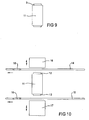
- Figure 9 shows a stopper body (3) located with a stopper holding means. The two ends of the stopper protrude from the ends of the stopper holding means.
- Figure 10 is a schematic of the process of the invention immediately prior to the pressing step.
- a stopper holding means (11) with two ends of a stopper (12) and (13) protruding therefrom as in Figure 9 .
- polymeric films (14) and (15) provided as part of a continuous film and backing plates (16) and (17) which are arranged to press the film onto the ends of the stopper. After the compression is complete, the backing plates (16) and (17) are released and the film advances in the direction shown to treat a further stopper.
- the polymeric films include voids (18) and (19) showing where polymeric film has been punched out of the continuous film during treatment of the previous stopper.
- a 20 micron multilayer film containing a 15 micron high density polyethylene layer with a 5 micron ethylene-vinyl acetate copolymer (EVA) layer was produce using conventional coextrusion blown film equipment.
- EVA ethylene-vinyl acetate copolymer
- a 40 micron multilayer film containing layers of EVA/PE/PVDC/Nylon was produced by extrusion and laminating using conventional techniques.
- a number of the coated corks were then chamfered by rotating the edges on sandpaper to produce tapered corks.
- the cross-sectional area of the surface of the stopper was less than the cross-sectional area of the body of the stopper. R values of 0.92, 0.83, 0.79 and 0.75 were thereby produced.
- corks were waxed and silicone coated by tumbling 100 corks with solid paraffin wax for 20 minutes and then with squirting 1 ml of 7004 CAF silicone on the corks and tumbling for a further 30 minutes. This was done to improve insertion of the corks into the bottle neck.
- the amount of air that enters the bottle at bottling can be seen by applying a vacuum at bottling and inverting the bottle and watching the air bubbles that stream into the bottle. (0 - no streaming; 5 - maximum amount of streaming)
- R value Area Ra Quantity of bubbles entering bottle 1.08 531 1.17 5 1.0 453 1 4 0.92 380 0.84 3.5 0.83 314 0.69 1 0.79 284 0.63 0 0.75 255 0.56
- Ra Surface area of end of stopper/cross-sectional area of the stopper.
- oxygen transmission is at optimal levels when the stopper body has a taper.
- the optimal taper will vary according to the properties of the compressible material of the stopper, the properties of the coating film and the dimensions of the opening into which it is ultimately inserted.
- Travel Test Another test that distinguishes the sealing ability of corks is known as the Travel Test. This test measures the number of bottles that allow wine to travel up between the cork and the bottle neck. The distance the wine travels is recorded. The test is accelerated by laying the bottles down and heating them to 30°C for a week. The heat increases the pressure the wine exerts on the seal. With film coated corks travel is usually associated with wine soaking underneath the film. The degree of this under soak can also be measured.
- corks Four coated corks were tested by this method. Some of the corks were altered by gluing a 4 mm thick transverse cut cork disk onto the end of the cork prior to coating with a polymer film. Each cork type was 24 mm diameter by 44 mm long in their completed form.
- Transverse cut means the disk was cut in a direction perpendicular to the direction cork for wine stoppers is usually cut.
- the end face of the disk originally faced into or away from the tree trunk. Therefore the lenticels (or air holes that originally allowed air to pass through the bark to the tree) pass from one face of the disk to the other. Natural cork stoppers are not cut in this direction because the wine can travel up through the lenticels from the inside end of the cork to the outside end.
- the end face of a cork stopper originally faced either the ground or the sky and the lenticels pass across the body of the cork.
- each of the corks was coated with a 60 micron film consisting of the layers EVA/PE/PVDC/Nylon/EVA/HDPE by heating and pressing the film onto the cork at 125°C as described in example 1.
- the corks Prior to bottling, the corks were coated with wax and silicone by tumbling for 60 minutes with approximately 0.0087g wax and 0.0064g of silicone per cork. The travel and under film soak results for six repeats of each cork after storage at 30°C for three weeks were as shown in the following table.
- stoppers with a chamfered end have improved performance characteristics as opposed to natural cork. It is also clear that the use of a substantially uniformly compressible region or layer on the end of the stopper body also improves stopper performance. A combination of these features is clearly superior.
Landscapes
- Engineering & Computer Science (AREA)
- Mechanical Engineering (AREA)
- Closures For Containers (AREA)
Claims (5)
- . Korken, der einen komprimierbaren Körper (3) aus Kork mit mindestens einer abgeflachten Endfläche aufweist, wobei die Kante (8,9) der Endfläche abgeschrägt ist und wobei eine Sperrschichtfolie (1) auf der Endfläche aufgeklebt ist, dadurch gekennzeichnet, dass sich die Sperrschichtfolie nicht über die Endfläche des nicht komprimierten Korkens erstreckt und mit einer Schicht aus wärmeaktiviertem Klebstoff auf der Endfläche aufgeklebt ist, so dass beim Komprimieren des Körpers beim Einsetzen des Korkens in eine Behälteröffnung der Bereich des Korkens an der Endfläche komprimiert wird, ohne dass dadurch die Schutzschicht zwischen dem Körper und dem Inhalt wesentlich negativ beeinträchtigt wird.
- . Korken nach Anspruch 1, bei dem das Verhältnis des Durchmessers der Endfläche innerhalb der abgeschrägten Kante zum Durchmesser des nicht komprimierten Korkenkörpers entfernt von der Endfläche kleiner als 1 und vorzugsweise kleiner als 0,92 ist.
- . Korken nach einem der vorhergehenden Ansprüche, bei dem die Sperrschichtfolie (1) aus Ethylen-Vinylalkohol-Copolymerisat, Polyvinyldichlorid und Metallfolien ausgewählt ist.
- . Verfahren zum Herstellen eines Korkens nach einem der Ansprüche 1. bis 3, bei dem der Korken, der mindestens eine abgeflachte Endfläche hat, bearbeitet wird, um eine Abschrägung (4,5) an der Kante dieser Endfläche zu bilden, und ein Laminat (1), das sich nicht über die Endfläche des Korkens hinaus erstreckt und eine Sperrschicht sowie eine wärmeaktivierte Klebeschicht beinhaltet, gegen die Endfläche gepresst wird, um die Sperrschicht auf die Endfläche zu kleben, wobei die Erwärmung der Folie entweder gleichzeitig mit oder vor dem Schritt des Pressens stattfindet.
- . Verpacktes Produkt mita. einem Behälter mit einer Öffnung, undb. einem sich in dem Behälter befindlichen Produkt,
dadurch gekennzeichnet, dassc. ein Behälter-Korken nach einem der Ansprüche 1-3, in die Öffnung eingesetzt ist.
Applications Claiming Priority (5)
| Application Number | Priority Date | Filing Date | Title |
|---|---|---|---|
| AUPP611501 | 2001-07-04 | ||
| AUPR6115A AUPR611501A0 (en) | 2001-07-04 | 2001-07-04 | Coating method |
| AUPR9097A AUPR909701A0 (en) | 2001-11-26 | 2001-11-26 | End coatings |
| AUPP909701 | 2001-11-26 | ||
| PCT/AU2002/000877 WO2003004367A1 (en) | 2001-07-04 | 2002-07-03 | Container stopper |
Publications (3)
| Publication Number | Publication Date |
|---|---|
| EP1401721A1 EP1401721A1 (de) | 2004-03-31 |
| EP1401721A4 EP1401721A4 (de) | 2006-05-31 |
| EP1401721B1 true EP1401721B1 (de) | 2009-01-07 |
Family
ID=25646741
Family Applications (1)
| Application Number | Title | Priority Date | Filing Date |
|---|---|---|---|
| EP02748421A Expired - Lifetime EP1401721B1 (de) | 2001-07-04 | 2002-07-03 | Korken für behälter |
Country Status (14)
| Country | Link |
|---|---|
| US (1) | US20040178168A1 (de) |
| EP (1) | EP1401721B1 (de) |
| JP (1) | JP2004532777A (de) |
| CN (1) | CN1288040C (de) |
| AR (1) | AR040322A1 (de) |
| AT (1) | ATE420033T1 (de) |
| AU (1) | AU2002318964B8 (de) |
| CA (1) | CA2453032A1 (de) |
| DE (1) | DE60230753D1 (de) |
| ES (1) | ES2321168T3 (de) |
| NZ (1) | NZ529774A (de) |
| PT (1) | PT1401721E (de) |
| WO (1) | WO2003004367A1 (de) |
| ZA (1) | ZA200309923B (de) |
Families Citing this family (24)
| Publication number | Priority date | Publication date | Assignee | Title |
|---|---|---|---|---|
| US20030102283A1 (en) * | 2001-12-03 | 2003-06-05 | Fox Robert W. | Composite closure for removable insertion into wine or similar style bottle |
| ATE465099T1 (de) * | 2002-03-06 | 2010-05-15 | Bacchus Technologies Ltd | Stopfen |
| AU2003254400B2 (en) * | 2002-08-29 | 2009-06-18 | Nukorc Trading International Ltd Sa Ag | Synthetic cork with tapered edge by heat shrinking and method thereof |
| AU2002951062A0 (en) * | 2002-08-29 | 2002-09-12 | Nukorc Pty Ltd | An improved synthetic closure and a method of forming thereof |
| CA2496722C (en) * | 2002-08-30 | 2011-10-11 | Suntory Limited | Container stopper and manufacturing method therefor |
| AU2003900034A0 (en) * | 2003-01-07 | 2003-01-23 | Procork Pty Ltd | Method and apparatus for applying a film |
| JP4462953B2 (ja) * | 2004-02-13 | 2010-05-12 | サントリーホールディングス株式会社 | 容器用栓とその製法 |
| BE1016664A3 (nl) * | 2005-06-30 | 2007-04-03 | Indurub Nv | Werkwijze en inrichting voor het vervaardigen van kurken uit kunststof. |
| DE102006013102A1 (de) * | 2006-03-20 | 2007-09-27 | Henkel Kgaa | Diffusionsreduzierende Korkbeschichtung |
| US20070262165A1 (en) * | 2006-05-09 | 2007-11-15 | Landau Steven M | System and method for altering the aroma within the head space of a container |
| US20080078737A1 (en) * | 2006-10-02 | 2008-04-03 | Brennan Christopher H | Unique wine flavor protector |
| BRPI0604459B1 (pt) * | 2006-10-03 | 2014-04-15 | Jose Norberto Pinto Coelho | Processo de obtenção de rolhas a partir da aglomeração de materiais mistos |
| PT103591B (pt) | 2006-10-17 | 2010-03-23 | Inst Superior Tecnico | Processo de produção de corpos cilíndricos de material compósito de cortiça, destinados à produção de rolhas para vinhos de pressão, bem como as rolhas produzidas por este processo |
| AU2007321722B2 (en) * | 2006-11-17 | 2011-01-20 | Procork Pty Ltd | Improved closure |
| EP2199042A1 (de) * | 2008-12-18 | 2010-06-23 | Technic One S.A. | Abschräggeräte für zylinderförmige Verschlüsse |
| US20100213160A1 (en) * | 2009-02-23 | 2010-08-26 | Mark Vella | Wine cork stamp |
| EP2347969B1 (de) * | 2010-01-25 | 2015-08-05 | Nomacorc LLC | Behälterstöpsel mit einer Dekorschicht |
| CN103043274A (zh) * | 2012-12-27 | 2013-04-17 | 杨兰钦 | 一种环保包装罐的制作工艺 |
| US8807363B1 (en) * | 2013-05-19 | 2014-08-19 | James R. Gilliam | Wine cork having molded anti-taint barrier tip |
| ITPD20130277A1 (it) | 2013-10-08 | 2015-04-09 | Microcell Srl | Tappo perfezionato per contenitori |
| JP6218321B2 (ja) * | 2013-12-13 | 2017-10-25 | 内山工業株式会社 | 樹脂被覆コルク栓 |
| JP2015178366A (ja) * | 2014-03-19 | 2015-10-08 | 内山工業株式会社 | 樹脂被覆コルク栓 |
| CN108485168A (zh) * | 2018-04-08 | 2018-09-04 | 慈溪市山今高分子塑料有限公司 | 一种红酒瓶塞及其制备工艺 |
| CN111452163A (zh) * | 2020-03-17 | 2020-07-28 | 广州傲胜人造草股份有限公司 | 一种包覆型软木颗粒及其制备方法 |
Family Cites Families (14)
| Publication number | Priority date | Publication date | Assignee | Title |
|---|---|---|---|---|
| FR983488A (fr) * | 1949-05-13 | 1951-06-25 | Perfectionnement aux bouchons en liège | |
| FR1534142A (fr) * | 1967-08-09 | 1968-07-26 | Bouchon en liège à embouts plastifiés | |
| GB1572902A (en) * | 1976-04-29 | 1980-08-06 | Metal Box Co Ltd | Closures for liquid product containers |
| US4854125A (en) * | 1987-02-20 | 1989-08-08 | Honda Giken Kogyo Kabushiki Kaisha | Hydrostatically operated continuously variable transmission |
| JPH03140231A (ja) * | 1989-10-26 | 1991-06-14 | Nissho Corp | バイアル用ゴム栓 |
| DE4225092A1 (de) * | 1991-08-01 | 1993-02-04 | Reinhard Kessler | Flaschenstoepsel aus elastischem kunststoff |
| JPH05293051A (ja) * | 1991-09-12 | 1993-11-09 | Frank Murray | 容器の開口部用の栓 |
| WO1993012980A1 (en) * | 1991-12-30 | 1993-07-08 | Finke Stephan J | Methods and combinations for sealing corked bottles |
| FR2786753B1 (fr) * | 1998-12-04 | 2001-01-19 | Barange Fabrique De Bouchons E | Bouchon composite a permeabilite controlee |
| AUPP989299A0 (en) * | 1999-04-22 | 1999-05-13 | Vinpac International Pty Ltd | Treated closures 1 |
| DE29912842U1 (de) * | 1999-07-22 | 1999-09-16 | Heinrich Gueltig Korkwarenfabr | Flaschenkorken |
| IT1319887B1 (it) * | 2000-02-07 | 2003-11-12 | Guala Dispensing Spa | Chiusura per contenitori, in particolare tappo per bottiglie. |
| IT1320789B1 (it) * | 2000-08-01 | 2003-12-10 | Mondo Spa | Tappo per contenitori, quali ad esempio bottiglie di vino, e relativoaccessorio. |
| ATE465099T1 (de) * | 2002-03-06 | 2010-05-15 | Bacchus Technologies Ltd | Stopfen |
-
2002
- 2002-07-03 US US10/482,384 patent/US20040178168A1/en not_active Abandoned
- 2002-07-03 CA CA002453032A patent/CA2453032A1/en not_active Abandoned
- 2002-07-03 DE DE60230753T patent/DE60230753D1/de not_active Expired - Fee Related
- 2002-07-03 WO PCT/AU2002/000877 patent/WO2003004367A1/en active IP Right Grant
- 2002-07-03 PT PT02748421T patent/PT1401721E/pt unknown
- 2002-07-03 AT AT02748421T patent/ATE420033T1/de not_active IP Right Cessation
- 2002-07-03 NZ NZ529774A patent/NZ529774A/en unknown
- 2002-07-03 ES ES02748421T patent/ES2321168T3/es not_active Expired - Lifetime
- 2002-07-03 CN CN02813424.9A patent/CN1288040C/zh not_active Expired - Fee Related
- 2002-07-03 AU AU2002318964A patent/AU2002318964B8/en not_active Ceased
- 2002-07-03 EP EP02748421A patent/EP1401721B1/de not_active Expired - Lifetime
- 2002-07-03 JP JP2003510349A patent/JP2004532777A/ja active Pending
- 2002-07-04 AR ARP020102512A patent/AR040322A1/es active IP Right Grant
-
2003
- 2003-12-22 ZA ZA200309923A patent/ZA200309923B/en unknown
Also Published As
| Publication number | Publication date |
|---|---|
| ES2321168T3 (es) | 2009-06-03 |
| CN1527782A (zh) | 2004-09-08 |
| EP1401721A4 (de) | 2006-05-31 |
| DE60230753D1 (de) | 2009-02-26 |
| EP1401721A1 (de) | 2004-03-31 |
| PT1401721E (pt) | 2009-04-09 |
| ATE420033T1 (de) | 2009-01-15 |
| NZ529774A (en) | 2004-10-29 |
| US20040178168A1 (en) | 2004-09-16 |
| ZA200309923B (en) | 2004-09-27 |
| AU2002318964B2 (en) | 2005-05-12 |
| JP2004532777A (ja) | 2004-10-28 |
| AR040322A1 (es) | 2005-03-30 |
| AU2002318964B8 (en) | 2005-09-29 |
| CA2453032A1 (en) | 2003-01-16 |
| CN1288040C (zh) | 2006-12-06 |
| WO2003004367A1 (en) | 2003-01-16 |
Similar Documents
| Publication | Publication Date | Title |
|---|---|---|
| EP1401721B1 (de) | Korken für behälter | |
| AU2002318964A1 (en) | Container stopper | |
| CA2705822C (en) | Multi-component synthetic closure and method of manufacture | |
| EP2396238B1 (de) | Synthetischer verschluss | |
| CA2185573C (en) | Interlocked fibre stopper | |
| NZ338076A (en) | Synthetic composite closure with foamed plastics inner and outer cores | |
| EP2590869B1 (de) | Behälterstöpsel mit einer Dekorschicht | |
| EP3157728B1 (de) | Mehrteiliger synthetischer verschluss und herstellungsverfahren dafür | |
| US20090236355A1 (en) | Container stopper | |
| US20060151510A1 (en) | Container stopper | |
| EP2508441B1 (de) | Verschluss/Stöpsel mit daran angeklebter mehrschichtiger Folie | |
| US20060124232A1 (en) | Method and apparatus for applying a film to a container stopper | |
| AU2004203776A1 (en) | Method and apparatus for applying a film to a container stopper | |
| AU2008322801B2 (en) | Multi-component synthetic closure and method of manufacture |
Legal Events
| Date | Code | Title | Description |
|---|---|---|---|
| PUAI | Public reference made under article 153(3) epc to a published international application that has entered the european phase |
Free format text: ORIGINAL CODE: 0009012 |
|
| 17P | Request for examination filed |
Effective date: 20031110 |
|
| AK | Designated contracting states |
Kind code of ref document: A1 Designated state(s): AT BE BG CH CY CZ DE DK EE ES FI FR GB GR IE IT LI LU MC NL PT SE SK TR |
|
| AX | Request for extension of the european patent |
Extension state: AL LT LV MK RO SI |
|
| A4 | Supplementary search report drawn up and despatched |
Effective date: 20060421 |
|
| 17Q | First examination report despatched |
Effective date: 20060724 |
|
| 17Q | First examination report despatched |
Effective date: 20060724 |
|
| GRAP | Despatch of communication of intention to grant a patent |
Free format text: ORIGINAL CODE: EPIDOSNIGR1 |
|
| GRAS | Grant fee paid |
Free format text: ORIGINAL CODE: EPIDOSNIGR3 |
|
| GRAA | (expected) grant |
Free format text: ORIGINAL CODE: 0009210 |
|
| AK | Designated contracting states |
Kind code of ref document: B1 Designated state(s): AT BE BG CH CY CZ DE DK EE ES FI FR GB GR IE IT LI LU MC NL PT SE SK TR |
|
| AX | Request for extension of the european patent |
Extension state: RO |
|
| REG | Reference to a national code |
Ref country code: GB Ref legal event code: FG4D |
|
| REG | Reference to a national code |
Ref country code: CH Ref legal event code: EP |
|
| REG | Reference to a national code |
Ref country code: IE Ref legal event code: FG4D |
|
| REF | Corresponds to: |
Ref document number: 60230753 Country of ref document: DE Date of ref document: 20090226 Kind code of ref document: P |
|
| REG | Reference to a national code |
Ref country code: PT Ref legal event code: SC4A Free format text: AVAILABILITY OF NATIONAL TRANSLATION Effective date: 20090401 |
|
| PG25 | Lapsed in a contracting state [announced via postgrant information from national office to epo] |
Ref country code: NL Free format text: LAPSE BECAUSE OF FAILURE TO SUBMIT A TRANSLATION OF THE DESCRIPTION OR TO PAY THE FEE WITHIN THE PRESCRIBED TIME-LIMIT Effective date: 20090107 |
|
| NLV1 | Nl: lapsed or annulled due to failure to fulfill the requirements of art. 29p and 29m of the patents act | ||
| REG | Reference to a national code |
Ref country code: ES Ref legal event code: FG2A Ref document number: 2321168 Country of ref document: ES Kind code of ref document: T3 |
|
| PG25 | Lapsed in a contracting state [announced via postgrant information from national office to epo] |
Ref country code: FI Free format text: LAPSE BECAUSE OF FAILURE TO SUBMIT A TRANSLATION OF THE DESCRIPTION OR TO PAY THE FEE WITHIN THE PRESCRIBED TIME-LIMIT Effective date: 20090107 |
|
| PG25 | Lapsed in a contracting state [announced via postgrant information from national office to epo] |
Ref country code: SE Free format text: LAPSE BECAUSE OF FAILURE TO SUBMIT A TRANSLATION OF THE DESCRIPTION OR TO PAY THE FEE WITHIN THE PRESCRIBED TIME-LIMIT Effective date: 20090407 Ref country code: AT Free format text: LAPSE BECAUSE OF FAILURE TO SUBMIT A TRANSLATION OF THE DESCRIPTION OR TO PAY THE FEE WITHIN THE PRESCRIBED TIME-LIMIT Effective date: 20090107 |
|
| PG25 | Lapsed in a contracting state [announced via postgrant information from national office to epo] |
Ref country code: BE Free format text: LAPSE BECAUSE OF FAILURE TO SUBMIT A TRANSLATION OF THE DESCRIPTION OR TO PAY THE FEE WITHIN THE PRESCRIBED TIME-LIMIT Effective date: 20090107 |
|
| PG25 | Lapsed in a contracting state [announced via postgrant information from national office to epo] |
Ref country code: DK Free format text: LAPSE BECAUSE OF FAILURE TO SUBMIT A TRANSLATION OF THE DESCRIPTION OR TO PAY THE FEE WITHIN THE PRESCRIBED TIME-LIMIT Effective date: 20090107 Ref country code: CZ Free format text: LAPSE BECAUSE OF FAILURE TO SUBMIT A TRANSLATION OF THE DESCRIPTION OR TO PAY THE FEE WITHIN THE PRESCRIBED TIME-LIMIT Effective date: 20090107 Ref country code: EE Free format text: LAPSE BECAUSE OF FAILURE TO SUBMIT A TRANSLATION OF THE DESCRIPTION OR TO PAY THE FEE WITHIN THE PRESCRIBED TIME-LIMIT Effective date: 20090107 |
|
| PLBE | No opposition filed within time limit |
Free format text: ORIGINAL CODE: 0009261 |
|
| STAA | Information on the status of an ep patent application or granted ep patent |
Free format text: STATUS: NO OPPOSITION FILED WITHIN TIME LIMIT |
|
| PG25 | Lapsed in a contracting state [announced via postgrant information from national office to epo] |
Ref country code: SK Free format text: LAPSE BECAUSE OF FAILURE TO SUBMIT A TRANSLATION OF THE DESCRIPTION OR TO PAY THE FEE WITHIN THE PRESCRIBED TIME-LIMIT Effective date: 20090107 |
|
| 26N | No opposition filed |
Effective date: 20091008 |
|
| PG25 | Lapsed in a contracting state [announced via postgrant information from national office to epo] |
Ref country code: BG Free format text: LAPSE BECAUSE OF FAILURE TO SUBMIT A TRANSLATION OF THE DESCRIPTION OR TO PAY THE FEE WITHIN THE PRESCRIBED TIME-LIMIT Effective date: 20090407 |
|
| PG25 | Lapsed in a contracting state [announced via postgrant information from national office to epo] |
Ref country code: MC Free format text: LAPSE BECAUSE OF NON-PAYMENT OF DUE FEES Effective date: 20090731 |
|
| REG | Reference to a national code |
Ref country code: CH Ref legal event code: PL |
|
| REG | Reference to a national code |
Ref country code: IE Ref legal event code: MM4A |
|
| PG25 | Lapsed in a contracting state [announced via postgrant information from national office to epo] |
Ref country code: CH Free format text: LAPSE BECAUSE OF NON-PAYMENT OF DUE FEES Effective date: 20090731 Ref country code: LI Free format text: LAPSE BECAUSE OF NON-PAYMENT OF DUE FEES Effective date: 20090731 |
|
| PG25 | Lapsed in a contracting state [announced via postgrant information from national office to epo] |
Ref country code: DE Free format text: LAPSE BECAUSE OF NON-PAYMENT OF DUE FEES Effective date: 20100202 |
|
| PG25 | Lapsed in a contracting state [announced via postgrant information from national office to epo] |
Ref country code: IE Free format text: LAPSE BECAUSE OF NON-PAYMENT OF DUE FEES Effective date: 20090703 |
|
| PG25 | Lapsed in a contracting state [announced via postgrant information from national office to epo] |
Ref country code: GR Free format text: LAPSE BECAUSE OF FAILURE TO SUBMIT A TRANSLATION OF THE DESCRIPTION OR TO PAY THE FEE WITHIN THE PRESCRIBED TIME-LIMIT Effective date: 20090408 |
|
| PG25 | Lapsed in a contracting state [announced via postgrant information from national office to epo] |
Ref country code: LU Free format text: LAPSE BECAUSE OF NON-PAYMENT OF DUE FEES Effective date: 20090703 |
|
| PG25 | Lapsed in a contracting state [announced via postgrant information from national office to epo] |
Ref country code: TR Free format text: LAPSE BECAUSE OF FAILURE TO SUBMIT A TRANSLATION OF THE DESCRIPTION OR TO PAY THE FEE WITHIN THE PRESCRIBED TIME-LIMIT Effective date: 20090107 |
|
| PG25 | Lapsed in a contracting state [announced via postgrant information from national office to epo] |
Ref country code: CY Free format text: LAPSE BECAUSE OF FAILURE TO SUBMIT A TRANSLATION OF THE DESCRIPTION OR TO PAY THE FEE WITHIN THE PRESCRIBED TIME-LIMIT Effective date: 20090107 |
|
| PGFP | Annual fee paid to national office [announced via postgrant information from national office to epo] |
Ref country code: GB Payment date: 20120716 Year of fee payment: 11 |
|
| PGFP | Annual fee paid to national office [announced via postgrant information from national office to epo] |
Ref country code: ES Payment date: 20120713 Year of fee payment: 11 |
|
| GBPC | Gb: european patent ceased through non-payment of renewal fee |
Effective date: 20130703 |
|
| PG25 | Lapsed in a contracting state [announced via postgrant information from national office to epo] |
Ref country code: GB Free format text: LAPSE BECAUSE OF NON-PAYMENT OF DUE FEES Effective date: 20130703 |
|
| PGFP | Annual fee paid to national office [announced via postgrant information from national office to epo] |
Ref country code: PT Payment date: 20140624 Year of fee payment: 13 |
|
| PGFP | Annual fee paid to national office [announced via postgrant information from national office to epo] |
Ref country code: FR Payment date: 20140624 Year of fee payment: 13 |
|
| PGFP | Annual fee paid to national office [announced via postgrant information from national office to epo] |
Ref country code: IT Payment date: 20140513 Year of fee payment: 13 |
|
| REG | Reference to a national code |
Ref country code: PT Ref legal event code: MM4A Free format text: LAPSE DUE TO NON-PAYMENT OF FEES Effective date: 20160104 |
|
| PG25 | Lapsed in a contracting state [announced via postgrant information from national office to epo] |
Ref country code: IT Free format text: LAPSE BECAUSE OF NON-PAYMENT OF DUE FEES Effective date: 20150703 |
|
| REG | Reference to a national code |
Ref country code: FR Ref legal event code: ST Effective date: 20160331 |
|
| PG25 | Lapsed in a contracting state [announced via postgrant information from national office to epo] |
Ref country code: FR Free format text: LAPSE BECAUSE OF NON-PAYMENT OF DUE FEES Effective date: 20150731 Ref country code: PT Free format text: LAPSE BECAUSE OF NON-PAYMENT OF DUE FEES Effective date: 20160104 |
|
| PG25 | Lapsed in a contracting state [announced via postgrant information from national office to epo] |
Ref country code: ES Free format text: LAPSE BECAUSE OF NON-PAYMENT OF DUE FEES Effective date: 20140704 |