TECHNICAL FIELD
The present invention relates to double surface metallized film used for
capacitors and, more particularly, to a method of manufacturing double surface
metallized film, and a capacitor using the same.
BACKGROUND ART
A capacitor made from plastic film with metal vacuum deposited thereon
(hereinafter referred to as metallized film capacitor) is conventionally widely
employed. Particularly, metallized film capacitors using polypropylene (hereinafter
referred to as PP) film which has excellent electrical characteristics (such as low
dielectric loss, high withstand voltage, less change in dielectric constant due to
temperature or frequency) are widely employed in various fields of applications
ranging from small-sized electronic equipments represented by a portable equipment
to large-sized industrial purposes such as a drive motor control for trains and a high-voltage
phase advancer.
Fig. 8 is a sectional view of a conventional metallized film capacitor
using PP film. Two sheets of PP film 42 with metal 41 vacuum deposited on one
side are wound or laminated, to which a metal is thermally sprayed to form
metallikon 34, thereby forming a capacitor. As the deposited metal 41, aluminum,
zinc, or their mixture has been widely used, but in a case of using aluminum, an
adhesive strength to the metallikon 34 is low, and when voltage is applied for a long
period of time, there arises a problem such that a capacity is reduced due to
oxidation and deterioration of aluminum. Accordingly, zinc or mixture of zinc and
aluminum is recently employed in many cases.
As the deposited metal 41, as shown in Fig. 8, widely employed is a
heavy edge structure wherein the deposited metal of capacity forming portion is
decreased in thickness to enhance the self-restoring property (in a case of local
dielectric breakdown of the film, the capacitor restores its function by eveporating
and dispersing the adjacent deposited metal to cut off electrically), and the portion
coming in contact with metallikon 34 is increased in thickness to enhance the
strength of contact with metallikon 34.
In the conventional configuration, since two sheets of PP film with metal
vacuum deposited on one side are used, a step of vacuum deposition is required for
each of the films, resulting in an increase of a man power. The step of vacuum
deposition can be halved if it is possible to vacuum deposit metal on both sides of
the PP film (hereinafter referred to as double surface metallized PP film) in a single
step of vacuum deposition and to realize a laminated structure (see Fig. 7) with a
vacuum deposition-free polypropylene film (hereinafter referred to as laminating PP
film).
However, when metal is vacuum deposited on both sides, the film has to
be once wound up to product roll 3 (see Fig. 1) in vacuum deposition apparatus 1
(see Fig. 1), and in that case, deposited metals on both sides become into contact
with each other. PP film has low adhesive strength to the deposited metal because
of low wettability, and also the tightning during the winding (stress accumulated in
the product roll) of the product roll is very high. Therefore, the metals on both sides
become bonded with each other, and there arises a problem such that the metals on
both sides peel off each other (hereafter called blocking) when the film is unwound
from the product roll in the next step (a step of slitting the vacuum deposited film or
a step of winding the capacitor). As disclosed in U.S. Patent No. 3,895,129, it is
known that the blocking is more remarkable when the deposited metal is zinc as
compared with aluminum.
When a capacitor is manufactured by using double surface vacuum
deposited PP film affected by the blocking, the double surface deposited metals peel
off each other in the step of slitting or winding, causing the function as a capacitor
electrode to be deteriorated and tanδ (dielectric tangent) to be increased.
Accordingly, for using double surface vacuum deposited PP film for capacitors, it is
absolutely required to solve the problem of the blocking.
From this point of view, manufacturing methods for suppressing the
occurrence of the blocking have been proposed. For example, U.S. Patent No.
3,895,129 discloses a method of manufacturing vacuum depositing zinc on both
sides of PP film, in which air is sprayed to the vacuum deposited surface on one side
to oxidize the deposited metal surface, followed by winding up the film to a product
roll.
Also, Japanese Patent Publication No. H7-62238 discloses a method of
vacuum deposition of zinc, zinc alloy or other metal on both sides of synthetic resin
film, in which oxidizing gas such as air and oxygen is injected into a film winding
chamber, that is isolated by a partition wall from a vacuum depositing chamber, in a
vacuum chamber. That is, a metal is first vacuum deposited on one side of the PP
film, and then oxidizing gas is sprayed to the vacuum deposited surface to oxidize
the vacuum deposited film. After that, the metal is vacuum deposited on another
side of the film, and then oxidizing gas is sprayed to the vacuum deposited surface.
However, the problem of the blocking cannot be solved by using the
manufacturing methods disclosed in U.S. Patent No. 3,895,129 and Japanese Patent
Publication No. H7-62238 with respect to the double surface vacuum deposited PP
film using zinc or mixture of zinc and aluminum.
Namely, in each of the manufacturing methods disclosed in U.S. Patent
No. 3,895,129 and Japanese Patent Publication No. H7-62238, air or oxidizing gas
is sprayed to the vacuum deposited surface of the PP film moving at a high speed,
but since the PP film moving speed in the vacuum depositing process is generally
300 m to 1000 m per minute, the surface is just exposed to the air or oxidizing gas
for extremely short time of less than 1/100 (one hundredth) second. In such a short
period of time, in the case of vacuum deposited film formed of zinc or zinc-aluminum
mixture, sufficient oxide layer is not formed. Accordingly, the
manufacturing methods are not enough to solve the problem of the blocking.
Particularly, as a double surface vacuum deposited PP film for capacitors,
PP film longer than 10,000 m is continuously vacuum deposited as a common
method, but in a product roll of such a long film, tightning during the winding or
stress is accumulated from outside to inside on the inner periphery (portion close to
the winding core), and therefore, the blocking takes place with an insufficient oxide
layer. If a capacitor is manufactured by using such double surface vacuum
deposited PP film, there arises the problem of the increase in tanδ of the capacitor as
described above.
Also, since the blocking is a phenomenon caused due to the deposited
metals on a back and a front surface bond with each other, when the film is stored
for a long period of time in a state of the product roll, there occurs problems such as
the blocking due to the insufficient oxide layer and the increase of tanδ during the
manufacturing of the capacitors.
Further, when an roll of the vacuum deposited film is affected by
moisture during a long-time storage or a transportation, there arises a problem of
secondary occurrence of a blocking. Such occurrence of the blocking due to
moisture is remarkable in the case of zinc or zinc-aluminum deposited metal, and
this is because zinc easily changes to oxide or hydroxide due to moisture.
Particularly, when PP film is used as the film, since it is poor in adhesive
strength to the deposited metal as compared with other film, there is a problem such
that the deposited metals on the front and back surface peel off from the film as they
are bonded with each other due to moisture.
As described above, when a capacitor is manufactured by using the
double surface metallized film affected by the blocking, there are problems such as
lowering of withstand voltage due to wrinkles produced during slitting or winding
operation and detereorating of tanδ as an electrode resistance is increased due to
removal of the vacuum deposited film, oxidation or hydroxylation of the deposited
metal.
Accordingly, when the double surface metallized film is stored or
transported in a state of the roll, it is necessary to keep the storing place under low
humidity as compared with conventional single-side metallized film, or to enclose
the film together with a drying agent in the package.
The present invention addresses to provide a method of manufacturing an
excellent double surface metallized PP film that is free from the blocking even when
zinc or zinc-aluminum mixture is vacuum deposited on both sides of long PP film,
and even in a case the film is exposed to moisture. Also, another object of the
present invention is to provide an excellent capacitor that is less in man power in the
production and free from increase in tanδ due to the blocking by using the double
surface vacuum deposited PP film of the present invention.
DISCLOSURE OF THE INVENTION
A method of manufacturing double surface metallized insulating film of
the present invention includes a step of vacuum depositing of zinc or zinc-aluminum
mixture on both sides of the insulating film, wherein oxidizing gas is sprayed to a
vacuum deposited film on an inner surface of the insulating film wound up in a step
of winding up to a product roll. Also, in a step of vacuum depositing of zinc or
zinc-aluminum mixture is vacuum deposited on both sides of the insulating film, an
oil layer is formed on at least one side of the deposited film, and an oxide layer is
formed by exposing at least one side of the deposited film to oxygen-contained gas,
or by spraying oxygen-contained gas to at least one side of the deposited film in a
step of winding up the insulating film to a product roll. It is preferable to use PP
film as an insulating film.
BRIEF DESCRIPTION OF THE DRAWINGS
Fig. 1 is an explanatory view showing a method of manufacturing double
surface metallized PP film in exemplary embodiment 1 of the present invention.
Fig. 2 is a partially enlarged view of a blowout port for spraying
oxidizing gas in the exemplary embodiment 1 of the present invention.
Fig. 3 is an explanatory view showing a method of manufacturing double
surface metallized PP film in exemplary embodiment 2 of the present invention.
Fig. 4 is a partially enlarged view of an oil layer forming portion in the
exemplary embodiment 2 of the present invention.
Fig. 5 is a partially enlarged view of a nozzle of the oil layer forming
portion in the exemplary embodiment 2 of the present invention.
Fig. 6 is an enlarged sectional view close to an oxygen exposing section
in Fig. 3.
Fig. 7 is an explanatory view of a metallized film capacitor in the
exemplary embodiment 1 of the present invention.
Fig. 8 is an explanatory view of a conventional metallized film capacitor.
Fig. 9 is an explanatory view of a metallized film capacitor in the
exemplary embodiment 2 of the present invention.
Fig. 10 is an analysis chart of oil layer of the metallized film capacitor in
the exemplary embodiment 2 of the present invention.
Fig. 11 is an analysis chart of oxide layer of a metallized film capacitor in
the exemplary embodiment 1 of the present invention.
DESCRIPTION OF THE PREFERRED EMBODIMENTS
Exemplary embodiment 1
The exemplary embodiment 1 of the present invention will be described
in the following with reference to Fig. 1, Fig. 2, and Fig. 11 where examples are
using PP film as an insulating film.
In Fig. 1, PP film 4 is unwound from raw material roll 2 installed in
vacuum deposition apparatus 1, and primary side deposited metal is formed on one
side of the PP film 4 on primary side cooling can 5a using primary side aluminum
evaporating source 6a and zinc evaporating source 7a . Then, secondary side
deposited metal is formed on another side of the PP film 4 on secondary side
cooling can 5b using secondary side aluminum evaporating source 6b and zinc
evaporating source 7b . Partition wall 16 is disposed for the purpose of partitioning
the vacuum deposition chamber so that a degree of vacuum in the vicinity of the
vacuum depositing sources 5a, 5b, 6a, and 6b is not affected by gas or moisture
adsorbed in the PP film 4 in the raw material roll 2. The partition wall 16 has been
conventionally used.
Next, the PP film 4 with metal vacuum deposited on both sides is wound
up to product roll 3 via roller 11 (see Fig. 2) disposed at follow-up drive section 8.
In this case, oxidizing gas 10 from blowout port 9 disposed at the follow-up drive
section 8 is sprayed to the inner surface of the PP film 4 to be wound up. The
follow-up drive section 8, as shown in the enlarged view of Fig. 2, is a mechanism
that follows up a radius of the product roll 3 that increases in size during vacuum
deposition, by driving pinion gear 13, and rotates about rotary shaft 12. By keeping
a distance between the roll 11 disposed on the follow-up drive section 8 and the
product roll 3 constant, the PP film 4 can be uniformly wound up to the product roll
3 even in a case of vacuum deposition to a long continuous film.
The oxidizing gas 10 is sprayed from the blowout port 9 through piping
14, while the flow rate is adjusted by flow rate control valve 15, for example. In the
configuration of the present invention, the oxidizing gas 10 sprayed is included in
the product roll 3. Consequently, the deposited surfaces on both sides of the PP film
4 are exposed to the oxidizing gas 10 for a long time, and thereby, oxide layer is
reliably formed. In this way, it is possible to prevent the blocking of vacuum
deposited surfaces on both sides of the film.
The installing position of the blowout port 9 is not limited in particular
provided that oxidizing gas 10 can be sprayed to an inner side of the winding. For
example, in the case of vacuum deposition on long PP film 4 exceeding 10,000 m, it
is desirable to install the blowout port on the follow-up drive section 8. That is,
even when the radius of the product roll 3 is increased during vacuum deposition,
the oxidizing gas 10 can be sprayed with a distance and an angle kept constant.
Therefore, reliable blocking preventing effect can be obtained over an entire
surfaces of the long PP film 4.
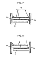
Fig. 7 is a sectional view of a double surface vacuum deposited PP film
capacitor. The PP film capacitor includes double surface vacuum deposited PP film
32 and laminating PP film 33, wherein an electrode is led out by means of
metallikon (thermally sprayed metal) 34 bonding to vacuum deposited electrode 31.
Next, blocking of double surface vacuum deposited PP film 32
manufactured in the exemplary embodiment 1 will be described in comparison with
the prior art.
As the exemplary embodiment, double surface vacuum deposited PP
films 32 as described below is manufactured by using PP film 4 of 4 µm thick and
15,000 m long.
Exemplary embodiment 1 - 1:
Zinc is vacuum deposited on both sides of the PP film 4, and oxygen is
sprayed by the method shown in Fig. 1 before winding up the PP film 4 to the
product roll 3.
Exemplary embodiment 1 - 2:
Zinc-aluminum mixture is vacuum deposited on both sides of the PP film
4, and air is sprayed by the method shown in Fig. 1 before winding up the PP film 4
to the product roll 3.
Exemplary embodiment 1 - 3:
Zinc-aluminum mixture is vacuum deposited on both sides of the PP film
4, and oxygen is sprayed by the method shown in Fig. 1 before winding up the PP
film 4 to the product roll 3.
Next, after taking the product roll 3 out of the vacuum deposition
apparatus, double surface vacuum deposited PP film 32 at the outermost periphery
and the innermost periphery of the product roll 3 were unwound and sampled, then
the peeled state of the deposited metal 31 was observed using a transmission
microscope having a magnification of 50 and photographed. The photograph was
digitally processed by a computer, by binary-coding a portion with the deposited
metal 31 peeled off and a portion being free from the peeled off to obtain a peeling
rate of the deposited metal 31 by percentage. For the comparison, double surface
vacuum deposited PP films based on the prior art, the peeling rates were obtained
with respect to the following samples.
Prior art 1 - 1:
Zinc is vacuum deposited on both sides of a PP film 4, and the PP film 4
is wound up to the product roll 3 woithout any treatment.
Prior art 1 - 2:
Zinc-aluminum mixture is vacuum deposited on both sides of the PP film
4, and air is sprayed by the method shown in Fig. 1 of Japanese Patent Publication
No. H7-62238 before winding up the PP film 4 to the product roll 3.
Prior art 1 - 3:
Zinc-aluminum mixture is vacuum deposited on both sides of the PP film
4, and oxygen is sprayed by the method shown in Fig. 1 of Japanese Patent
Publication No. H7-62238 before winding up the PP film 4 to the product roll 3.
The peeling rates of the deposited metal on each sample are shown in
Table 1. In the present exemplary embodiment, the peeling rate of the deposited
metal is very low even at the inner periphery of the
product roll 3 where stresses are
accumulated, and it is shown that an excellent double surface vacuum deposited PP
film that cannot be obtained by the prior art can be produced.
| | Oxidizing gas | Vacuum deposited metal | Peeling rate of deposited metal (%) |
| | | | Outermost periphery of product roll | Innermost periphery of product roll |
| Exemplary embodiment 1 - 1 | Oxygen | Zinc | 0.3 | 0.8 |
| Exemplary embodiment 1 - 2 | Air | Zinc+Aluminum | 0.4 | 0.9 |
| Exemplary embodiment 1 - 3 | Oxygen | Zinc+Aluminum | 0.0 | 0.1 |
| Prior art 1 - 1 | None | Zinc | 6.2 | 38.6 |
| Prior art 1 - 2 | Air | Zinc+Aluminum | 2.2 | 8.3 |
| Prior art 1 - 3 | Oxygen | Zinc+Aluminum | 0.8 | 4.8 |
Next, capacitors (10 uF) shown in Fig. 7 are produced by winding the
double surface vacuum deposited PP film 32 manufactured in the exemplary
embodiment 1 and the laminating PP film 33, and, as an example of capacitor
characteristics in the present exemplary embodiment, tanδ at 1 kHz is measured.
In each of the capacitors, film at the innermost periphery of the product
roll 3 was used as the double surface vacuum deposited PP film 32.
The results are shown in Table 2. Tanδ of the capacitors based on the
prior art become increased because of increase in serial equivalent resistance due to
the peeling of the electrodes, while tanδ of the capacitors based on the present
exemplary embodiment are low, showing excellent characteristics.
| | tanδ |
| Exemplary embodiment 1 - 1 | 0.05 |
| Exemplary embodiment 1 - 2 | 0.05 |
| Exemplary embodiment 1 - 3 | 0.03 |
| Prior art 1 - 1 | 0.48 |
| Prior art 1 - 2 | 0.18 |
| Prior art 1 - 3 | 0.15 |
In the exemplary embodiment 1, the PP film 4 of 4 µm thick is used, and
similar effects are also obtained in using other films of different thickness.
Also, the exemplary embodiment of the present invention is shown in Fig.
1 and Fig. 2, but the exemplary embodiment is not limited to these. Similar effects
can be obtained by using a manufacturing method wherein oxidizing gas 10 is
sprayed to the inner side of the PP film wound up to the product roll 3 in the
vacuum depositing process in which zinc or zinc-aluminum mixture is vacuum
deposited on both sides of the PP film 4 unwound from the raw material roll 2.
Also, oxygen and air are shown as oxidizing gas 10, but the present
exemplary embodiment is not limited to these gas. Similar effects can be obtained
by using ozone or other oxidizing gas, or gas that forms a passive state on the
surface of the deposited metal. Further, in the above description, PP film is
described as an example of the insulating film, but the manufacturing method of the
present invention can be effectively applied to various kinds of insulating films
other than PP film such as polyethylene telephthalate, polyethylene naphthalate,
polyamide, and other insulating films.
Exemplary embodiment 2
The exemplary embodiment 2 of the present invention will be described
in the following with reference to Fig. 3 to Fig. 6, and Figs. 9 to Fig. 11.
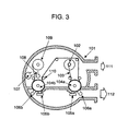
Fig. 3 is a sectional view of a double surface metallized film
manufacturing apparatus in the exemplary embodiment 2 of the present invention.
Metal is vacuum deposited on a front and a back surfaces of film 103
from aluminum evaporating source 105a, 105b and zinc evaporating source 106a,
106b when the film 103 unwound from unwinding section 102 in vacuum chamber
101 passes through cooling cans 104a and 104b. Then, oil layer is formed on the
film 103 at oil layer forming section 107, and after the film is exposed to oxygen at
oxygen exposure section 108, it is wound up by winding section 109 to be a raw
material roll of a double surface metallized film. In Fig. 3, reference numeral 110
stands for an intermediate roll for film transportation, and reference numerals 111,
112 stand for an evacuation by a vacuum pump. Also, the aluminum evaporating
source 105a, 105b and zinc evaporating source 106a, 106b can evaporate only
aluminum, only zinc, and also, a mixture of aluminum and zinc depending on the
purpose.
Fig. 4 is an enlarged sectional view in a vicinity of the oil layer forming
section 107. Oil 122, heater 123, temperature sensor 126, and pressure sensor 127
are housed in a cylindrical oil tank 120. The oil 122 heated by the heater 123 spouts
from nozzle 128 in the form of oil vapor 124, and thereby, oil layer 129 is formed
on vacuum deposited film 121 on the film 103 that moves in a direction shown by
the arrow. The temperature sensor 126 and the pressure sensor 127 are disposed for
monitoring the temperature and pressure in the oil tank 120. Particularly, in a step
of metallizing a long film, the amount of oil spouted during vacuum deposition is
kept constant by the pressure sensor 127, and thereby, the oil layer can be uniformly
formed on the vacuum deposited film 121.
Fig. 5 shows a shape of nozzle 128. Oil vapor spouts from slit 130
disposed in the nozzle 128 to form oil layer on the film 103 (not shown). By
disposing the slit 130 intermittently as shown in Fig. 5, the oil layer can be formed
only on capacitance forming portions of the metallized film (refer to 81 in Fig. 9).
Fig. 6 is an enlarged sectional view in a vicinity of the oxygen exposure
section 108. Gas 131 containing oxygen is introduced into cylindrical pipe 132
from outside the vacuum chamber (not shown), and the gas is sprayed from holes
133 in the pipe 132 to the vacuum deposited film 121 on the inner side of the film
103 to be wound, and in this way, the vacuum deposited film can be exposed to
oxygen for a long period of time. Although it is not shown in Fig. 6, the holes 133
are formed at equal intervals over a entire width of the film.
The evaluation results of the blocking of the double surface metallized
film in the exemplary embodiment 2 of the present invention are described in the
following. Double surface metallized films shown in Table 3 are manufactured
using the manufacturing apparatus shown in Fig. 3 with use of PP film of 6 µm
thick and 520 mm wide. Each of a length of the vacuum deposited film is 3000 m.
The vacuum deposition was executed so as to make the resistance of the vacuum
deposited film to be 12 Ω per unit area.
The double surface metallized films manufactured in this way are keft in
an atmosphere of a temperature of 40°C and a relative humidity of 60 % for 20 days
in a state of an raw material roll. Then, the films are cut by a slitter and checked for
an existtence of wrinkling, and also, the resistance of the vacuum deposited films
are measured. The results are shown in Table 3.
| | Deposited metal | Oil layer | Exposure atmosphere | Wrinkling due to slitting | Resistance of vacuum deposited film
(Ω) |
| Exemplary embodiment 2 - 1 | Aluminum + Zinc | Silicone oil | Oxygen | No | | 12 |
| Exemplary embodiment 2 - 2 | Aluminum + Zinc | Silicone oil | Air | No | 17 |
| Exemplary embodiment 2 - 3 | Aluminum + Zinc | Fluoro-carbon oil | Oxygen | No | | 12 |
| Exemplary embodiment 2 - 4 | Aluminum + Zinc | Paraffin oil | Oxygen | No | | 15 |
| Exemplary embodiment 2 - 5 | Zinc | Silicone oil | Oxygen | No | | 13 |
| Prior art 2 - 1 | Aluminum + Zinc | None | Oxygen | Occured | 23 |
| Prior art 2 - 2 | Zinc | None | Oxygen | Occured | 42 |
| Comparative example | Aluminum + Zinc | Silicone oil | None | Occured | 28 |
As is obvious from Table 3, in a case of double surface metallized film in
the prior art and the comparative example, wrinkles are produced during slitting
operation due to the blocking, and the resistance of the vacuum deposited film is
increased, while in a case of the exemplary embodiment, wrinkles does not occurr,
and also, an increase of the resistance is suppressed. Particularly, in a case where
the silicone oil or the fluoro-carbon oil is used for the oil layer, excellent results that
show no increase in the resistance can be obtained.
Next, a metallized film capacitor shown in Fig. 9 is manufactured by
using the double surface metallized film in the exemplary embodiment 2 - 1 and the
prior art example 2 - 1. In Fig. 9, double surface metallized film 32 with metal 31a,
31b deposited on both sides and laminating PP film 33 are wound. Also, oil layer
81 and oxide layer 82 are formed on the double surface metallized film 32 by the
process disclosed in the present exemplary embodiment.
As to the metallized film capacitor manufactured as recited above, tests
were conducted with respect to tanδ at 1 kHz and withstand voltage at 60 Hz. In the
withstand voltage test, the voltage causing short-circuitting of the capacitor is
decided as the withstand voltage, where the voltage applied to the capacitor is
increased by 50V per minute at an ambient temperature of 70°C. The results are
shown in Table 4.
In a case of the capacitor of the prior art 2-1, tanδ is high due to the
blocking, and also, the withstand voltage is low due to the wrinkles produced during
the slitting operation. On the other hand, the capacitor of the present exemplary
embodiment is excellent in tanδ and withstand voltage.
| | tanδ (%) | Withstand voltage (AC, V) |
| Exemplary embodiment 2-1 | 0.05 | 1350 |
| Prior art 2-1 | 0.18 | 1050 |
The existence of the oil layer in the present invention can be observed,
for example, by using an energy dispersion type X-ray analyzer attached to an
electron microscope after sampling double surface metallized film from the
capacitor and measuring the deposited metal as it is, or extracting the oil using a
proper solvent and condensing the solution. As an example, a result of an analysis
of the metallized film capacitor of the exemplary embodiment 2 are shown in Fig.
10. In the figure, the abscissa shows the characteristic X-ray energy of the elements
consisting of the double surface metallized film, and the ordinate shows the strength
of each characteristic X-ray. The peak shown by circle 151 in the figure
corresponds to silicone element, representing the existence of the oil layer composed
of silicone oil.
Also, the existence of oxide layer in the present invention can be
observed, for example, by analyzing the surface of the deposited film using X-ray
photoelectron spectroscopy (hereinafter referred to as ESCA). As an example, a
resuls of an analysis of the metallized film capacitor of the exemplary embodiment 1
are shown in Fig. 11. In Fig. 11, the abscissa shows a binding energy of zinc of the
deposited metal, and a peak is detected at about 262 eV in a case of zinc metal, and
at about 267 eV in a case of zinc oxide. Curve 152 in Fig. 11 is a result of an
analysis of the vacuum deposited film surface, and curve 153 is a result of an
internal portion of the deposited film that is obtained by removing the vacuum
deposited film surface by etching. The curve 152 of the vacuum deposited film
surface has a large peak of zinc oxide, showing the existence of the oxide layer.
The manufacturing apparatus shown in Figs. 3 to 6 is shown as an
example in the exemplary embodiment 2, but the manufacturing apparatus for the
present invention is not limit to this apparatus. Similar effects can be obtained by
using a manufacturing apparatus for double surface metallized film comprising a
metal depositing section for forming a deposited metal film on both sides of the film,
an oil layer forming section for forming oil layer on at least one side of the
deposited films formed by the metal depositing section, and an oxygen exposure
section for exposing the deposited film surface on at least one side of the vacuum
deposited films formed by the metal depositing section to an oxygen-contained
atmosphere.
For example, with the arrangement in Fig. 3, the film passes through the
oxygen exposure section after passing through the oil layer forming section, but
similar effects can also be obtained by exchanging the position of the sections. Also,
the oil layer formed surface can be either one of the same surface or opposite
surface to the surface exposed to oxygen. This is because when the double surface
metallized film is wound up at the winding section 109 of Fig. 3, the deposited films
on the front surface and on the back surface come into contact with each other via
the oil layer, and therefore, the influence of moisture can be suppressed against both
surfaces. Naturally, it is also possible to form the oil layer on both surfaces.
Also, in Fig. 4, oil vapor is spouted from slits at the oil layer forming
section, however, spouting holes at equal intervals may be provided instead of the
slits.
Also, in Fig. 3, oxygen or air is sprayed at the oxygen exposure section,
but similar effects can be obtained by exposing the film to an oxygen-containing
atmosphere by other method. For example, a casing filled with oxygen-containing
gas may be provided in the vacuum chamber, through which the film is passed to
expose the deposited film 121 to oxygen.
Further, an example of a sectional view of a metallized film capacitor in
the exemplary embodiment is shown in Fig. 9, but the present invention is not
limited to the example. For example, similar effects can be obtained even when the
deposited films 31a, 31b have uniform thickness instead of heavy edge structures.
Exemplary embodiment 3
In order to study the influences of surface conditions of PP film 4, PP
films 4 having different surface wetting indexes are prepared by changing the
corona discharge conditions for PP film 4. The "surface wetting index" described in
the present exemplary embodiment is defined in JIS K-6768.
Next, double surface vacuum deposited
PP film 32 was manufactured by
vacuum depositing aluminum and zinc on both sides of
PP film 4 and spraying
oxygen thereto by the method shown in Fig. 1. The
PP film 4 used has a thickness
of 6 µm and length of 2,000 m, maximum surface roughness Rmax = 1.3 µm,
average surface roughness Ra = 0.15 µm, and an isotacticity of 97%, where the
surface roughness is measured by the method specified in JIS B-0601. The
deposited film peeling rates and an appearance of the
product roll 3 were observed.
The results are shown in Table 5.
| Surface wetting index (dyn/cm) | Peeling rate of deposited film | Appearance of product roll |
| Primary side | Secondary side | Innermost periphery of product roll |
| 34 | 34 | 0.0 | Good |
| 37 | 37 | 0.0 | Good |
| 41 | 41 | 0.0 | Good |
| 33 | 33 | 0.8 | Good |
| 42 | 42 | 0.0 | Film wrinkling |
| 44 | 44 | Film breaking during vacuum deposition | Film breaking during vacuum deposition |
When the surface wetting index of the PP film 4 is less than 34 dyn/cm,
the adhesion between deposited metal 31 and PP film 4 is lowered, and
consequently, the peeling rate of the deposited film increases by 0.8 %. Also, when
the surface wetting index exceeds 41 dyn/cm, the PP films 4 come in contact with
each other in the raw material roll 2 and cannot be smoothly unwound, causing
generation of wrinkling on the product roll 3 and breaking of the film. The surface
wetting index of PP film can be set by changing the corona discharge condition or
changing a time period from corona discharge until the vacuum deposition.
When the surface wetting indexes on both sides of the PP film 4 are in a
range of 34 to 41 dyn/cm, there is no occurrence of the blocking, and moreover, the
obtained double surface vacuum deposited PP film 32 shows good appearance on
the product roll 3. Also, similar results are obtained with regard to the exemplary
embodiment 2.
Next, in order to study the influences of the surface roughness of the
PP
film 4,
PP films 4 having different surface roughness were manufactured, and
double surface vacuum deposited
PP film 32 are manufactured by vacuum
depositing aluminum and zinc on both sides of the film and spraying oxygen thereto
by the method shown in Fig. 1. The double surface vacuum deposited
PP films 32
are cut by a slitter to observe the generation of wrinkling during the slitting
operation. The results are shown in Table 6. The primary side and the secondary
side mean the both sides of the
PP film 32.
| Maximum surface roughness Rmax (µm) | Average surface roughness Ra (µm) | Wrinkling due to slitting |
| Primary side | Secondary side | Primary side | Secondary side |
| 1.75 | 1.72 | 0.16 | 0.18 | No |
| 1.54 | 1.46 | 0.14 | 0.14 | No |
| 1.12 | 1.08 | 0.10 | 0.11 | No |
| 1.05 | 0.90 | 0.10 | 0.08 | Occur |
| 0.91 | 0.92 | 0.09 | 0.08 | Occur |
When the maximum surface roughness Rmax is 1 µm or more and the
average surface roughness Ra is 0.1 µm or more, the wrinkle during capacitor
winding does not occur. Similar results are obtained in the exemplary embodiment
2.
Since metal is deposited on both sides of the double surface vacuum
deposited PP film, if the surface roughness is less than the above value, the double
surface vacuum deposited PP film will not smoothly move through many rollers
disposed in the slitter (not shown) that slits the double surface vacuum deposited PP
film to a predetermined width and in the film winding unit (not shown), causing the
generation of the wrinkle and zigzag motion of the film. In a case Rmax exceeds
2.0 µm, the PP film will become uneven in thickness, and then, the PP film is liable
to break at the thinnest portion when a voltage is applied to the capacitor
manufactured. Therefore, Rmax is preferably to be 2.0 µm or less.
Further, in order to study the stereoregularity of the
PP film 4,
PP films 4
having different isotacticity are prepared.
Product roll 3 of double surface vacuum
deposited
PP film 32 was manufactured by vacuum depositing aluminum and zinc
on both sides of the
PP films 4 and exposing it to oxygen gas by the method shown
in Fig. 1. The
product roll 3 was keft in an atmosphere of 40°C for 60 days to
observe the degree of the blocking. The results are shown in Table 7.
| Isotacticity (%) | Peeling rate of deposited metal (%) |
| | 7 days after vacuum deposition | 60 days after vacuum deposition |
| 96 | 0.0 | 0.0 |
| 97 | 0.0 | 0.0 |
| 95 | 0.0 | 0.3 |
When the isotacticity of the PP film 4 is 95%, thermal shrinkage of double
surface vacuum deposited PP film 32 occurs during 60 days keaping at 40°C,
causing the product roll 3 to become gradually wound tightly, an occurrence of the
blocking is observed, where the deposited metals 31 stick together and peel off each
other. When the isotacticity is 96% or more, thermal shrinkage is hard to occur
because the stereoregularity of the PP film 4 is enhanced, showing no occurrence of
the blocking. Accordingly, when the isotacticity is 96% or more, it is possible to
produce excellent double surface vacuum deposited PP film 32 having storageability
wherein the film is free from blocking even when stored for a long period of time in
a state of the product roll 3. Similar results are also obtained in the exemplary
embodiment 2.
INDUSTRIAL APPLICABILITY
As described above, according to the method of manufacturing double
surface metallized film of the present invention, oxidizing gas is also wound into the
product roll. Therefore, the oxidation of the vacuum deposited film occur even after
the vacuum deposited insulating film has been wound up to the product roll, and
sufficient oxide layer is formed on the surface of the deposited film. Thus, a double
surface vacuum deposited film which is free from blocking even when a long
insulating film is continuously vacuum deposited is obtained.
Also, according to the method of manufacturing of the present invention,
an excellent double surface metallized film that is free from the occurrence of the
blocking due to moisture even when the deposited film is stored for a long period of
time or transported in a state of a product roll can be obtained, because of the oil
layer formed on at least one side of the deposited film.
Further, according to the method of manufacturing of the present
invention, since oxidizing gas gets into the product roll and oil layer is formed on at
least one side of the film, an excellent double surface metallized film which is free
from the occurrence of blocking due to moisture even when a long insulating film is
continuously vacuum deposited is obtained.
Moreover, according to the method of manufacturing of the present
invention, the blowout port for spraying oxidizing gas moves in accordance with the
radius of the product roll that increases during the vacuum deposition. In this way,
the oxidizing gas can be sprayed from a constant distance during the operation from
the start of the vacuum deposition when the product roll is smaller in diameter until
the end of the vacuum deposition when the product roll is increased in diameter.
Accordingly, a double surface metallized film of uniform quality even when a long
film is continuously vacuum deposited is obtained.
Further, according to the manufacturing method of the present invention,
oxygen is used as an oxidizing gas, and therefore, it is possible to minimize the
deteriorating of degree of vacuum due to the oxidizing gas.
Further, according to the method of manufacturing double surface
metallized film of the present invention, chemically stable silicone oil or fluoro-carbon
oil is used as oil for forming oil layer. Accordingly, an excellent double
surface vacuum deposited film which is free from peeling of the deposited film and
free from an increase of resistance due to a permeation or a swelling of the oil into
the insulating film can be obtained.
Further, according to the method of manufacturing double surface
metallized film of the present invention, oil layer is formed on only a predetermined
portion in the widthwise direction of the film. Thus, a double surface vacuum
deposited film which is excellent in adhesiont with the metallikon is obtained.
Further, according to the method of manufacturing double surface
metallized film of the present invention, since oil vapor is sprayed to the film under
a non-contact condition, a double surface deposited film without scratching on the
deposited film can be obtained.
Further, according to the method of manufacturing double surface
metallized film of the present invention, oil vapor is sprayed to the deposited film
while monitoring the oil vapor pressure by a pressure sensor disposed in the oil tank.
Thus, an oil layer is formed on a long film at a constant rate.
Further, according to the method of manufacturing double surface
metallized PP film of the present invention, since the surface wetting index of the
PP film is set to be 34 to 41 dyn/cm for both sides thereof, an excellent double
surface vacuum deposited PP film which is excellent in adhesion between the
deposited metal and the PP film, and also, is free from a problem such that the PP
films stick to each other in the raw material roll is obtained.
Further, according to the method of manufacturing double surface
metallized PP film of the present invention, the surface roughness on at least one
side of the PP film is set to be the maximum roughness Rma of 1.0 to 2.0 µm, and
the average roughness Ra of 0.1 µm or more. Accordingly, there is no trouble such
as a generation of wrinkle and zigzag movement in the next step of slitting or
winding, and an double surface vacuum deposited PP film of excellent workability
is obtained.
Further, according to the method of manufacturing double surface
metallized PP film of the present invention, PP film of isotacticity of 96% or more is
used. Since the stereoregularity of crystal of the PP film is enhanced, the elastic
modulus of the PP film is improved, and as a result, the tightning during the winding
of the product roll can be decrreased. Accordingly, it is possible to obtain a double
surface vacuum deposited PP film which has excellent characteristics with respect
to storage and transportation when the film is stored for a long period of time or
transported in a state of product roll.
Further, in the process of a metallized film capacitor of the present
invention, only one step of the vacuum deposition is required, and a low-cost
capacitor having excellent electrical characteristics is obtained.