EP1400816A2 - Kraftfahrzeug- Funkradar und Signalbearbeitung - Google Patents
Kraftfahrzeug- Funkradar und Signalbearbeitung Download PDFInfo
- Publication number
- EP1400816A2 EP1400816A2 EP03021108A EP03021108A EP1400816A2 EP 1400816 A2 EP1400816 A2 EP 1400816A2 EP 03021108 A EP03021108 A EP 03021108A EP 03021108 A EP03021108 A EP 03021108A EP 1400816 A2 EP1400816 A2 EP 1400816A2
- Authority
- EP
- European Patent Office
- Prior art keywords
- radio wave
- radar
- vehicle
- frequency
- received
- Prior art date
- Legal status (The legal status is an assumption and is not a legal conclusion. Google has not performed a legal analysis and makes no representation as to the accuracy of the status listed.)
- Withdrawn
Links
Images






Classifications
-
- G—PHYSICS
- G01—MEASURING; TESTING
- G01S—RADIO DIRECTION-FINDING; RADIO NAVIGATION; DETERMINING DISTANCE OR VELOCITY BY USE OF RADIO WAVES; LOCATING OR PRESENCE-DETECTING BY USE OF THE REFLECTION OR RERADIATION OF RADIO WAVES; ANALOGOUS ARRANGEMENTS USING OTHER WAVES
- G01S7/00—Details of systems according to groups G01S13/00, G01S15/00, G01S17/00
- G01S7/02—Details of systems according to groups G01S13/00, G01S15/00, G01S17/00 of systems according to group G01S13/00
- G01S7/36—Means for anti-jamming, e.g. ECCM, i.e. electronic counter-counter measures
-
- G—PHYSICS
- G01—MEASURING; TESTING
- G01S—RADIO DIRECTION-FINDING; RADIO NAVIGATION; DETERMINING DISTANCE OR VELOCITY BY USE OF RADIO WAVES; LOCATING OR PRESENCE-DETECTING BY USE OF THE REFLECTION OR RERADIATION OF RADIO WAVES; ANALOGOUS ARRANGEMENTS USING OTHER WAVES
- G01S13/00—Systems using the reflection or reradiation of radio waves, e.g. radar systems; Analogous systems using reflection or reradiation of waves whose nature or wavelength is irrelevant or unspecified
- G01S13/02—Systems using reflection of radio waves, e.g. primary radar systems; Analogous systems
- G01S13/06—Systems determining position data of a target
- G01S13/08—Systems for measuring distance only
- G01S13/32—Systems for measuring distance only using transmission of continuous waves, whether amplitude-, frequency-, or phase-modulated, or unmodulated
- G01S13/34—Systems for measuring distance only using transmission of continuous waves, whether amplitude-, frequency-, or phase-modulated, or unmodulated using transmission of continuous, frequency-modulated waves while heterodyning the received signal, or a signal derived therefrom, with a locally-generated signal related to the contemporaneously transmitted signal
-
- G—PHYSICS
- G01—MEASURING; TESTING
- G01S—RADIO DIRECTION-FINDING; RADIO NAVIGATION; DETERMINING DISTANCE OR VELOCITY BY USE OF RADIO WAVES; LOCATING OR PRESENCE-DETECTING BY USE OF THE REFLECTION OR RERADIATION OF RADIO WAVES; ANALOGOUS ARRANGEMENTS USING OTHER WAVES
- G01S13/00—Systems using the reflection or reradiation of radio waves, e.g. radar systems; Analogous systems using reflection or reradiation of waves whose nature or wavelength is irrelevant or unspecified
- G01S13/02—Systems using reflection of radio waves, e.g. primary radar systems; Analogous systems
- G01S13/06—Systems determining position data of a target
- G01S13/08—Systems for measuring distance only
- G01S13/32—Systems for measuring distance only using transmission of continuous waves, whether amplitude-, frequency-, or phase-modulated, or unmodulated
- G01S13/36—Systems for measuring distance only using transmission of continuous waves, whether amplitude-, frequency-, or phase-modulated, or unmodulated with phase comparison between the received signal and the contemporaneously transmitted signal
- G01S13/38—Systems for measuring distance only using transmission of continuous waves, whether amplitude-, frequency-, or phase-modulated, or unmodulated with phase comparison between the received signal and the contemporaneously transmitted signal wherein more than one modulation frequency is used
-
- G—PHYSICS
- G01—MEASURING; TESTING
- G01S—RADIO DIRECTION-FINDING; RADIO NAVIGATION; DETERMINING DISTANCE OR VELOCITY BY USE OF RADIO WAVES; LOCATING OR PRESENCE-DETECTING BY USE OF THE REFLECTION OR RERADIATION OF RADIO WAVES; ANALOGOUS ARRANGEMENTS USING OTHER WAVES
- G01S13/00—Systems using the reflection or reradiation of radio waves, e.g. radar systems; Analogous systems using reflection or reradiation of waves whose nature or wavelength is irrelevant or unspecified
- G01S13/88—Radar or analogous systems specially adapted for specific applications
- G01S13/93—Radar or analogous systems specially adapted for specific applications for anti-collision purposes
- G01S13/931—Radar or analogous systems specially adapted for specific applications for anti-collision purposes of land vehicles
-
- G—PHYSICS
- G01—MEASURING; TESTING
- G01S—RADIO DIRECTION-FINDING; RADIO NAVIGATION; DETERMINING DISTANCE OR VELOCITY BY USE OF RADIO WAVES; LOCATING OR PRESENCE-DETECTING BY USE OF THE REFLECTION OR RERADIATION OF RADIO WAVES; ANALOGOUS ARRANGEMENTS USING OTHER WAVES
- G01S7/00—Details of systems according to groups G01S13/00, G01S15/00, G01S17/00
- G01S7/02—Details of systems according to groups G01S13/00, G01S15/00, G01S17/00 of systems according to group G01S13/00
- G01S7/40—Means for monitoring or calibrating
- G01S7/4004—Means for monitoring or calibrating of parts of a radar system
-
- G—PHYSICS
- G01—MEASURING; TESTING
- G01S—RADIO DIRECTION-FINDING; RADIO NAVIGATION; DETERMINING DISTANCE OR VELOCITY BY USE OF RADIO WAVES; LOCATING OR PRESENCE-DETECTING BY USE OF THE REFLECTION OR RERADIATION OF RADIO WAVES; ANALOGOUS ARRANGEMENTS USING OTHER WAVES
- G01S13/00—Systems using the reflection or reradiation of radio waves, e.g. radar systems; Analogous systems using reflection or reradiation of waves whose nature or wavelength is irrelevant or unspecified
- G01S13/02—Systems using reflection of radio waves, e.g. primary radar systems; Analogous systems
- G01S13/06—Systems determining position data of a target
- G01S13/46—Indirect determination of position data
- G01S2013/462—Indirect determination of position data using multipath signals
Definitions
- the present invention relates to an automotive radio wave radar and signal processing executed in the radar.
- a 76-GHz band is allocated as frequencies adapted for automotive radio wave radars used in vehicles, etc.
- automotive radio wave radars have the obligation to use a frequency range of 1 GHz from 76 GHz to 77 GHz.
- Japanese Unexamined Patent Application Publication No. 4-236388 discloses a technique of superimposing an ID signal on a radar wave radiated from a radio wave radar, determining from the ID signal as a determination basis whether a received radar wave is one radiated from another vehicle and having the same frequency as that radiated from a relevant vehicle, and changing the frequency of the radar wave radiated from the relevant vehicle when the received radar wave is one radiated from another vehicle and having the same frequency as that radiated from the relevant vehicle, thereby preventing erroneous detection.
- an object of the present invention is to provide an automotive radio wave radar and a signal processing method for use in the radar, which can prevent erroneous detection caused by jamming, including an interference, without requiring a special circuit and a determining unit and hence without increasing the cost.
- the present invention provides an automotive radio wave radar in which a radio wave modulated about a certain frequency is radiated from a transmit antenna forward of a relevant vehicle, a reflected radio wave from a vehicle running ahead or other object is received by a receive antenna, and/or at least a position of the vehicle running ahead relative to the relevant vehicle is computed.
- the radar can comprise an oscillation unit for oscillating a radio wave to be transmitted while changing a center frequency of the transmitted radio wave to different frequencies at a certain time interval; and/or a signal processing unit for computing position information of the vehicle running ahead for each of the center frequencies of the radio waves transmitted from the oscillation unit.
- the signal processing unit can execute decision by majority on the position information computed for at least three or more center frequencies, and/or when mismatching position information is computed with the occurrence of any jamming, can determine the position information, which has been decided to be minority with the decision by majority, to be an abnormal value and discards the abnormal value.
- results of the position information computed for at least three or more center frequencies can be subjected to decision by majority. If a mismatching result of the position information is computed on account of an interference with a radio wave transmitted from a radar equipped in another vehicle, the mismatching result can be determined to be an abnormal value with the decision by majority and then discarded. It is hence possible to prevent erroneous detection of an obstacle otherwise caused by the interference.
- the present invention provides an automotive radio wave radar in which a radio wave modulated about a certain frequency is radiated from a transmit antenna forward of a relevant vehicle, a reflected radio wave from a vehicle running ahead or other object is received by a receive antenna, and/or at least a position of the vehicle running ahead relative to the relevant vehicle is computed.
- the radar can comprise an oscillation unit for oscillating a radio wave to be transmitted while changing a center frequency of the transmitted radio wave to different frequencies at a certain time interval; and/or a signal processing unit for computing spectra from intermediate frequency signals resulting from down-converting received reflected radio waves of at least three or more center frequencies by a mixer, and/or when a part or the whole of at least one of the computed spectra is determined to have a different waveform with the occurrence of any jamming, determining the at least one spectrum to be abnormal, and discarding the abnormal spectrum.
- an oscillation unit for oscillating a radio wave to be transmitted while changing a center frequency of the transmitted radio wave to different frequencies at a certain time interval
- a signal processing unit for computing spectra from intermediate frequency signals resulting from down-converting received reflected radio waves of at least three or more center frequencies by a mixer, and/or when a part or the whole of at least one of the computed spectra is determined to have a different waveform with the occurrence of any jamm
- the determination as to the erroneous detection can be performed by comparing spectrum waveforms of the intermediate frequency (IF) signals which are obtained by down-converting the received reflected radio waves.
- IF intermediate frequency
- the automotive radio wave radar of the present invention is applicable to any of a 2-frequency CW (Continuous Wave) radar in which radio waves of two different frequencies can be alternately radiated forward of the relevant vehicle, reflected radio waves from the vehicle running ahead can be received by the receive antenna, and/or information of a range relative to the vehicle running ahead can be computed from a phase difference between the received radio waves of the two frequencies, and/or an FMCW (Frequency Modulated Continuous Wave) radar for transmitting a radio wave while performing frequency modulation to change a frequency of the transmitted radio wave in a predetermined pattern with time.
- a 2-frequency CW Continuous Wave
- FMCW Frequency Modulated Continuous Wave
- the present invention provides an automotive radio wave radar of the 2-frequency CW type in which radio waves of two different frequencies can be alternately radiated forward of a relevant vehicle, reflected radio waves from a vehicle running ahead can be received by a receive antenna, and/or information of a range relative to the vehicle running ahead can be computed from a phase difference between the received radio waves of the two frequencies, wherein the radar can include a signal processing unit for computing spectra of the radio waves of the two frequencies received by the radar, and when a part or the whole of at least one of the computed spectra is determined to have a different waveform with the occurrence of any jamming, determining the at least one spectrum to be abnormal.
- the determination as to the erroneous detection can be performed by comparing the spectra of the received radio waves of two frequencies.
- the automotive radio wave radar of the present invention can further comprise a unit for informing a driver of the fact that obstacle detection by the radar is disabled, when an interference occurs for plural center frequencies and received signals are all determined to be abnormal.
- a display unit for providing visual display and/or a speaker for issuing a voice output can be used to prompt the driver to pay attention.
- the present invention provides a signal processing method for use in an automotive radio wave radar, comprising the steps of radiating a radio wave modulated about a certain center frequency from a transmit antenna forward of a relevant vehicle, receiving a reflected radio wave from a vehicle running ahead or other object by a receive antenna, and/or detecting at least a position of the vehicle running ahead relative to the relevant vehicle, wherein the method can further comprise the steps of oscillating a radio wave to be transmitted while changing a center frequency of the transmitted radio wave to different frequencies at a certain time interval; computing position information of the vehicle running ahead for each of the center frequencies of the transmitted radio waves; executing decision by majority on the position information computed for at least three or more center frequencies; and/or when mismatching position information is computed with the occurrence of any jamming, determining the position information, which has been decided to be minority with the decision by majority, to be an abnormal value and discarding the abnormal value.
- the present invention provides a signal processing method for use in an automotive radio wave radar, can comprise the steps of radiating a radio wave modulated about a certain center frequency from a transmit antenna forward of a relevant vehicle, receiving a reflected radio wave from a vehicle running ahead or other object by a receive antenna, and/or detecting at least a position of the vehicle running ahead relative to the relevant vehicle, wherein the method further can comprise the steps of oscillating a radio wave to be transmitted while changing a center frequency of the transmitted radio wave to different frequencies at a certain time interval; computing spectra from intermediate frequency signals resulting from down-converting received reflected radio waves by a mixer; and/or when a part or the whole of at least one of the computed spectra is determined to have a different waveform with the occurrence of any jamming, determining the at least one spectrum to be abnormal and discarding the abnormal spectrum.
- the present invention provides a signal processing method for use in an automotive radio wave radar of the 2-frequency CW type, the method can comprise the steps of alternately radiating radio waves of two different frequencies forward of a relevant vehicle; receiving reflected radio waves from the vehicle running ahead by a receive antenna; and/or computing information of a range relative to the vehicle running ahead from a phase difference between the received radio waves of the two frequencies, wherein the method can further comprise the steps of computing spectra of the radio waves of the two frequencies received by the radar; and/or when a part or the whole of at least one of the computed spectra is determined to have a different waveform with the occurrence of any jamming, determining the at least one spectrum to be abnormal.
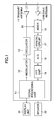
- Fig. 1 shows one embodiment of the automotive radio wave radar according to the present invention.
- the automotive radio wave radar comprises a signal processing unit 11, a modulator 12, an oscillator 13, a transmit antenna 14, a receive antenna 15, a mixer 16, an analog circuit 17, an A/D converter 18, and an FFT (Fast Fourier Transform) unit 19.
- a signal processing unit 11 a modulator 12, an oscillator 13, a transmit antenna 14, a receive antenna 15, a mixer 16, an analog circuit 17, an A/D converter 18, and an FFT (Fast Fourier Transform) unit 19.
- FFT Fast Fourier Transform
- the oscillator 13 receives a modulated signal from the modulator 12 and radiates a modulated high-frequency signal (radio wave) from the transmit antenna 14.
- the oscillator 13 oscillates a millimeter wave in a 76-GHz band as the high-frequency signal.
- the oscillator 13 is capable of oscillating the millimeter wave while changing the center frequency of the transmitted radio wave to different frequencies at a certain time interval.
- the oscillator 13 repetitively oscillates radio waves having three ore more center frequencies (CF1, CF2, CF3, ...) different from each other.
- a part of the output signal from the oscillator 13 is supplied to the mixer 16 through a directional coupler 20, and a beat signal generated with mixing of the output signal from the oscillator 13 and the received signal is sent to the analog circuit 17.
- the analog circuit 17 measures a rate (relative speed) and a range with respect to another vehicle by utilizing a Doppler frequency.
- the frequency of the beat signal outputted from the mixer 16 provides the Doppler frequency.
- the beat signal sent to the analog circuit 17 is converted to a digital signal by the A/D converter 18, and then supplied to the FFT unit 19. Based on a frequency spectrum of the beat signal, the FFT unit 19 measures information of amplitude and phase through Fourier analysis processing. The information of amplitude and phase is sent to the signal processing unit 11.
- the signal processing unit 11 is constituted by, e.g., a DSP (Digital Signal Processor) and includes, as shown in Fig. 2A, a position information computing unit 21, a filter unit 22, a data storage unit 23, and a position information output unit 24.
- DSP Digital Signal Processor
- the position information computing unit 21 computes position information (range, rate, and azimuth) of a vehicle running ahead at each center frequency (CF1, CF2, CF3, ...) based on the FFT analysis result for each of the center frequencies (CF1, CF2, CF3, ).
- the filter unit 22 executes decision by majority on the position information obtained from the radar waves at three center frequencies (CF1, CF2, CF3).
- the position information which has been decided to be minority with the decision by majority in the filter unit 22, is determined as an abnormal value and discarded. Values of the remaining true data (normal data) are averaged and stored in the data storage unit 23, and are also outputted to a display unit 31, e.g., a liquid crystal display shown in Fig. 2B, and to a speaker 32 from the position information output unit 24.
- Fig. 3 shows one example of a transmitted signal in the automotive radio wave radar according to the present invention.
- a 2-frequency CW (continuous wave) radar which radiates radio waves modulated to have two frequencies f1 and f2 for each center frequency set to the middle between the two frequencies and which measures the range up to an obstacle from a phase difference between the two radio waves received after being reflected by the obstacle, the transmitted signal is obtained by shifting the center frequency CF (f1, f2) at a certain cycle.
- the shift of the center frequency and the modulation to respective two frequencies are carried out by the modulator 12 under control of the signal processing unit 11.
- the signal processing is made on the transmitted signal with the two frequencies f1, f2 set as one frame, and the center frequency is shifted to CF1, CF2, CF3, ... in units of several frames.
- Fig. 4 shows one example of a spectrum waveform resulting from executing the FFT (Fast Fourier Transform) on the beat signal obtained from the mixer 16.
- FFT Fast Fourier Transform
- Rate C(fd1/2f1) where C: the velocity of light
- the above-mentioned method for computing the position information of the vehicle running ahead does not depend on the shift of the center frequency (CF1, CF2, CF3, ...) so long as the frequency width between f1 and f2 is not changed.
- step S11 it is determined whether a difference (deviation) between the position information (e.g., range value) computed from the signal at the center frequency CF1 and the position information computed from the signal at the center frequency CF2 is within a preset threshold (step S11).
- the position information e.g., range value
- step S11 If the difference is within the threshold (YES in step S11), it is then determined whether a difference (deviation) between the position information computed from the signal at the center frequency CF2 and the position information computed from the signal at the center frequency CF3 is within a preset threshold (step S12).
- step S12 If the difference is within the threshold (YES in step S12), this means that no jamming occurs.
- all data of the position information computed from the signal at the center frequency CF1, the position information computed from the signal at the center frequency CF2, and the position information computed from the signal at the center frequency CF3 are regarded as true data and used to compute an average value of those data (step S13).
- step S12 if the difference between the position information computed from the signal at the center frequency CF2 and the position information computed from the signal at the center frequency CF3 is not within the threshold (NO in step S12), this means that jamming occurs at the center frequency CF3.
- data of the position information computed from the signal at the center frequency CF1 and the position information computed from the signal at the center frequency CF2 are regarded as true data and used to compute an average value of those data (step S14).
- step S15 The difference between the position information computed from the signal at the center frequency CF1 and the position information computed from the signal at the center frequency CF2 is not within the threshold (NO in step S11), it is then determined whether a difference (deviation) between the position information computed from the signal at the center frequency CF1 and the position information computed from the signal at the center frequency CF3 is within a preset threshold (step S15).
- step S15 If the difference is within the threshold (YES in step S15), this means that jamming occurs at the center frequency CF2.
- data of the position information computed from the signal at the center frequency CF1 and the position information computed from the signal at the center frequency CF3 are regarded as true data and used to compute an average value of those data (step S16).
- step S17 The difference between the position information computed from the signal at the center frequency CF1 and the position information computed from the signal at the center frequency CF3 is not within the threshold (NO in step S15), it is then determined whether a difference (deviation) between the position information computed from the signal at the center frequency CF2 and the position information computed from the signal at the center frequency CF3 is within a preset threshold (step S17).
- step S17 If the difference is within the threshold (YES in step S17), this means that jamming occurs at the center frequency CF1.
- data of the position information computed from the signal at the center frequency CF2 and the position information computed from the signal at the center frequency CF3 are regarded as true data and used to compute an average value of those data (step S18).
- step S19 The difference between the position information computed from the signal at the center frequency CF2 and the position information computed from the signal at the center frequency CF3 is not within the preset threshold (NO in step S17), this means that any true data not subjected to jamming cannot be extracted. In this case, an alarm is issued (step S19).
- the fact that the radar detection is unable to perform i.e., the measurement is disabled
- the display on the display unit 31 in the event of jamming is performed, for example, by indicating a mark ⁇ 31B in a radar display area 31A as shown in Fig. 2B.
- a spectrum may be computed from an intermediate frequency (IF) signal resulting from down-converting the received reflected wave by the mixer 16.
- IF intermediate frequency
- the spectrum is determined to be abnormal and discarded. Then, an average value of true data can be obtained in accordance with a control flow similar to that of the logic for obtaining true data based on decision by majority shown in Fig. 6.
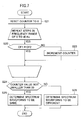
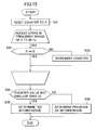
- a counter is reset to 0 (step S21). Then, it is determined whether a difference in signal intensity between the spectrum at the center frequency CF1 and the spectrum at the center frequency CF2 for each frequency (e.g., a sampling frequency per 1 Hz) over a predetermined frequency range (0 to 40 Hz) is within a preset threshold (step S22). If the difference is within the threshold, the counter is incremented (step S23). Both the determining step S22 and the counter incrementing step S23 are repeated over the frequency range 0 to 40 Hz.
- step S24 it is determined whether the counter value is not smaller than a predetermined value, e.g., 30 (step S24). If the counter value is not smaller than 30 (YES in step S24), the spectrum waveforms are determined to be the same (step S25). On the other hand, if the counter value is smaller than 30 (NO in step S24), the spectrum waveforms are determined to be different from each other (step S26).
- a predetermined value e.g. 30
- Fig. 8A shows a modulation pattern in the FMCW radar
- Fig. 8B shows Doppler frequency resulting from down-converting the transmitted wave and the received wave in the mixer.
- the FMCW radar differs from the 2-frequency CW radar in that, as shown in Fig. 8A, the frequency modulation is changed linearly with time (i.e., triangular modulation).
- the signal processing is performed with a rise zone and a fall zone of a triangular wave set as one frame, and the center frequency is shifted to CF1, CF2, CF3, ... in units of several frames.
- Doppler frequency is given as Fb1 in the rise zone and Fb2 in the fall zone of the triangular wave.
- a target e.g., the vehicle running ahead
- the frequencies Fb1, Fb2 at which peaks representing the target appear are in proportion to the range up to the target. Specifically, a frequency 0 indicates that the range is 0.
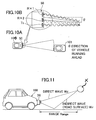
- FIG. 10A is an illustration showing a situation from above in which a relevant vehicle 100 equipped with a radio wave radar 50 is running following a vehicle 101 running ahead.
- Fig. 10B two receive antennas Rx1, Rx2 are provided for one transmit antenna Tx.
- the azimuth of the vehicle running ahead is measured from a ratio between signal intensities of two reflected waves received by the receive antennas Rx1, Rx2.
- a radio wave received through the shortest path from the vehicle 101 running ahead there are a direct wave received through the shortest path from the vehicle 101 running ahead, and an indirect wave received after being reflected by the road surface and the sidewall.
- a reflected wave received from a reflecting object X present at a certain range (Range) includes not only a direct wave Wd, but also an indirect wave Wir received after being reflected by the road surface.
- Fig. 12 shows a distribution of the amount of attenuation with respect to the range up to the reflecting object at a certain height resulting when the transmitted wave of a certain frequency is employed.
- the indirect wave received after being reflected by the sidewall also attenuates due to an interference with the indirect wave received after being reflected by the road surface and has a specific attenuation distribution.
- the indirect wave Wis received from the sidewall attenuates with the reflection by the sidewall and hence hardly has reception intensity stronger than that of the direct wave Wd. In most cases, therefore, correct measurement is performed based on the direct wave Wd when the azimuth of the vehicle running ahead is measured by the mono-pulse radar.
- the received signal of the direct wave Wd attenuates in larger amount than that of the indirect wave Wis from the sidewall, thus resulting in that the azimuth of the vehicle running ahead may be erroneously measured as indicated by a vehicle 101E.
- the azimuth is measured at three ore more center frequencies different from each other, and measured values are subjected to decision by majority. Accordingly, even when, although in a very few cases, the direct wave attenuates in larger amount at a certain frequency, a different signal processing result from the other results can be determined as an abnormal value with the decision by majority and discarded.
- the 2-frequency CW radar employs, as described above, the modulation method of radiating radio waves of two frequencies f1 and f2 with the center frequency set to the middle between those two frequencies.
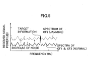
- a difference in waveform is caused in a part or the whole of a spectrum obtained with the frequency f1 and a spectrum obtained with the frequency f2 as seen from the spectra shown in Fig. 14.
- a peak frequency representing target information appears at different values P(f1) and P(f2) for the spectrum obtained with the frequency f1 and the spectrum obtained with the frequency f2.
- a fail signal can be outputted by comparing the spectrum waveforms of f1 and f2 and then determining the presence of an abnormality if the spectrum waveforms are determined to be different from each other.
- a counter is reset to 0 (step S31). Then, it is determined whether a difference in signal intensity between the spectrum obtained with the frequency f1 and the spectrum obtained with the frequency f2 for each frequency (e.g., a sampling frequency per 1 Hz) over a predetermined frequency range (0 to 40 Hz) is within a preset threshold (step S32).
- step S33 If the difference is within the threshold, the counter is incremented (step S33). Both the determining step S32 and the counter incrementing step S33 are repeated over the frequency range 0 to 40 Hz.
- step S34 it is determined whether the counter value is not smaller than a predetermined value, e.g., 30 (step S34). If the counter value is not smaller than 30 (YES in step S34), no interference is determined (step S35). On the other hand, if the counter value is smaller than 30 (NO in step S34), the presence of interference is determined (step S36).
- a predetermined value e.g. 30
- the automotive radio wave radar includes an oscillation unit for oscillating a radio wave to be transmitted forward of a relevant vehicle while changing a center frequency of the radio wave to different frequencies at a certain time interval.
- Position information of a vehicle running ahead is calculated for each of plural center frequencies of the radio waves transmitted from the oscillation unit.
- Results of the position information computed for at least three or more center frequencies are subjected to decision by majority. If a mismatching result of the position information is computed on account of an interference with a radio wave transmitted from a radar equipped in another vehicle, the mismatching result is determined to be an abnormal value with the decision by majority and then discarded. It is hence possible to prevent erroneous detection of an obstacle otherwise caused by the interference.
- erroneous detection is caused by, in addition to an interference with a radar wave transmitted from another vehicle, an interference of radio waves received through a plurality of paths of the radio wave transmitted from the relevant vehicle, which are formed with reflection by a road surface and/or sidewall, including the shortest one directly reflected from another vehicle.
- the erroneous detection can also be avoided through a similar process based the decision by majority.
- the determination regarding the erroneous detection can be performed by comparing spectrum waveforms of received signals of two frequencies.
- an automotive radio wave radar capable of avoiding erroneous detection caused by an interference can be realized without requiring a special circuit and a determining unit which are required in the related art, and hence without increasing the cost.
Landscapes
- Engineering & Computer Science (AREA)
- Radar, Positioning & Navigation (AREA)
- Remote Sensing (AREA)
- Physics & Mathematics (AREA)
- Computer Networks & Wireless Communication (AREA)
- General Physics & Mathematics (AREA)
- Electromagnetism (AREA)
- Radar Systems Or Details Thereof (AREA)
Applications Claiming Priority (2)
| Application Number | Priority Date | Filing Date | Title |
|---|---|---|---|
| JP2002275090 | 2002-09-20 | ||
| JP2002275090A JP3688255B2 (ja) | 2002-09-20 | 2002-09-20 | 車載用電波レーダ装置及びその信号処理方法 |
Publications (2)
| Publication Number | Publication Date |
|---|---|
| EP1400816A2 true EP1400816A2 (de) | 2004-03-24 |
| EP1400816A3 EP1400816A3 (de) | 2004-07-28 |
Family
ID=31944602
Family Applications (1)
| Application Number | Title | Priority Date | Filing Date |
|---|---|---|---|
| EP03021108A Withdrawn EP1400816A3 (de) | 2002-09-20 | 2003-09-19 | Kraftfahrzeug- Funkradar und Signalbearbeitung |
Country Status (3)
| Country | Link |
|---|---|
| US (1) | US6972710B2 (de) |
| EP (1) | EP1400816A3 (de) |
| JP (1) | JP3688255B2 (de) |
Cited By (6)
| Publication number | Priority date | Publication date | Assignee | Title |
|---|---|---|---|---|
| CN103703387A (zh) * | 2011-04-19 | 2014-04-02 | 马自达汽车株式会社 | 车辆用障碍物检测装置 |
| CN104765036A (zh) * | 2015-03-25 | 2015-07-08 | 王方圆 | 倒车雷达 |
| CN104777481A (zh) * | 2015-03-23 | 2015-07-15 | 王方圆 | 汽车防碰撞雷达系统 |
| CN104793208A (zh) * | 2015-03-25 | 2015-07-22 | 王方圆 | 抗干扰与多目标识别的汽车防撞雷达检测方法 |
| WO2020191927A1 (zh) * | 2019-03-22 | 2020-10-01 | 深圳迈睿智能科技有限公司 | 基于多普勒效应原理的微波探测器及抗辐射干扰方法 |
| WO2021108814A3 (en) * | 2021-02-18 | 2021-11-18 | Futurewei Technologies, Inc. | End-to-end self-controlled security in autonomous vehicles |
Families Citing this family (22)
| Publication number | Priority date | Publication date | Assignee | Title |
|---|---|---|---|---|
| JP3688255B2 (ja) * | 2002-09-20 | 2005-08-24 | 株式会社日立製作所 | 車載用電波レーダ装置及びその信号処理方法 |
| JP2004226158A (ja) * | 2003-01-21 | 2004-08-12 | Fujitsu Ten Ltd | Fm−cwレーダ装置 |
| JP4258328B2 (ja) * | 2003-09-12 | 2009-04-30 | オムロン株式会社 | 2周波ドップラ測距装置およびその装置を備えた検出システム |
| JP2005156337A (ja) * | 2003-11-26 | 2005-06-16 | Hitachi Ltd | 車載用レーダ装置 |
| EP1775600A4 (de) * | 2004-08-02 | 2007-09-05 | Mitsubishi Electric Corp | Radar-vorrichtung |
| JP4631476B2 (ja) * | 2005-03-04 | 2011-02-16 | トヨタ自動車株式会社 | 移動体用通信装置及び移動体用通信方法 |
| US20060256854A1 (en) * | 2005-05-16 | 2006-11-16 | Hong Jiang | Parallel execution of media encoding using multi-threaded single instruction multiple data processing |
| JP4754292B2 (ja) * | 2005-07-25 | 2011-08-24 | セコム株式会社 | レーダ装置 |
| WO2007043475A1 (ja) * | 2005-10-07 | 2007-04-19 | Kabushiki Kaisha Toshiba | レーダ装置とレーダサイト間調整方法 |
| US20070182623A1 (en) * | 2006-02-03 | 2007-08-09 | Shuqing Zeng | Method and apparatus for on-vehicle calibration and orientation of object-tracking systems |
| US7991550B2 (en) * | 2006-02-03 | 2011-08-02 | GM Global Technology Operations LLC | Method and apparatus for on-vehicle calibration and orientation of object-tracking systems |
| WO2008094172A2 (en) * | 2006-06-01 | 2008-08-07 | University Of Florida Research Foundation, Inc. | Radar microsensor for detection, tracking, and classification |
| JP5609184B2 (ja) * | 2010-03-18 | 2014-10-22 | 富士通株式会社 | レーダ装置及び周波数制御プログラム |
| US8432309B2 (en) * | 2010-11-29 | 2013-04-30 | Freescale Semiconductor, Inc. | Automotive radar system and method for using same |
| EP2699937A4 (de) * | 2011-04-20 | 2015-02-25 | Freescale Semiconductor Inc | Empfängervorrichtung, mehrfrequenzradarsystem und fahrzeug |
| US9080866B1 (en) * | 2013-06-26 | 2015-07-14 | Google Inc. | Methods and systems for detection of reflective markers at long range |
| JP2015224899A (ja) * | 2014-05-26 | 2015-12-14 | 株式会社デンソー | 車載レーダ装置 |
| JP2017187395A (ja) * | 2016-04-06 | 2017-10-12 | Ntn株式会社 | 見守り装置 |
| KR101887137B1 (ko) * | 2016-09-01 | 2018-09-10 | 현대자동차주식회사 | 동작 감지 장치, 동작 감지 방법 및 동작 감지 안테나 |
| DE102018200755A1 (de) * | 2018-01-18 | 2019-07-18 | Robert Bosch Gmbh | Verfahren und Vorrichtung zum Plausibilisieren einer Querbewegung |
| US11348380B2 (en) * | 2018-06-08 | 2022-05-31 | Metawave Corporation | Beacon system in an autonomous vehicle radar for vehicle identification |
| WO2021181658A1 (ja) * | 2020-03-13 | 2021-09-16 | 三菱電機株式会社 | レーダ装置 |
Family Cites Families (20)
| Publication number | Priority date | Publication date | Assignee | Title |
|---|---|---|---|---|
| US3383686A (en) * | 1967-01-30 | 1968-05-14 | Navy Usa | Diverse frequency echo detection system with doppler frequency coherence |
| FR2171961B1 (de) * | 1972-02-17 | 1979-04-27 | Labo Cent Telecommunicat | |
| US4400700A (en) * | 1981-06-08 | 1983-08-23 | The United States Of America As Represented By The Secretary Of The Army | Doppler frequency analysis of radar signals |
| US5017921A (en) * | 1989-12-13 | 1991-05-21 | Grumman Aerospace Corporation | Radar system and a method for operating a radar system |
| JP2932210B2 (ja) | 1991-01-18 | 1999-08-09 | マツダ株式会社 | 自動車のレーダシステム |
| US5280288A (en) * | 1992-08-14 | 1994-01-18 | Vorad Safety Systems, Inc. | Interference avoidance system for vehicular radar system |
| JP2868978B2 (ja) | 1993-07-30 | 1999-03-10 | 防衛庁技術研究本部長 | 短波レーダ装置 |
| JP3627389B2 (ja) * | 1995-09-28 | 2005-03-09 | 株式会社デンソー | レーダ装置 |
| US5828333A (en) * | 1997-01-21 | 1998-10-27 | Northrop Grumman Corporation | Multiple access diplex doppler radar |
| EP1253441B1 (de) | 2000-01-28 | 2010-04-07 | Hitachi, Ltd. | Entfernungsmessgerät |
| US6577269B2 (en) * | 2000-08-16 | 2003-06-10 | Raytheon Company | Radar detection method and apparatus |
| KR100852810B1 (ko) * | 2000-08-16 | 2008-08-18 | 레이던 컴퍼니 | 차량 레이더 시스템들과 기술들 |
| JP4111667B2 (ja) * | 2000-09-26 | 2008-07-02 | 富士通テン株式会社 | Fm−cwレーダ装置 |
| DE10108584A1 (de) * | 2001-02-22 | 2002-09-05 | Bosch Gmbh Robert | Verfahren zum Entstören einer Radareinrichtung und Radareinrichtung |
| JP2002372580A (ja) * | 2001-06-13 | 2002-12-26 | Mitsubishi Electric Corp | Fm−cwレーダ装置 |
| US6859705B2 (en) * | 2001-09-21 | 2005-02-22 | Ford Global Technologies, Llc | Method for operating a pre-crash sensing system with object classifier in a vehicle having a countermeasure system |
| JP3938686B2 (ja) * | 2001-12-13 | 2007-06-27 | 富士通株式会社 | レーダ装置、信号処理方法及びプログラム |
| US6587072B1 (en) * | 2002-03-22 | 2003-07-01 | M/A-Com, Inc. | Pulse radar detection system |
| US6873251B2 (en) * | 2002-07-16 | 2005-03-29 | Delphi Technologies, Inc. | Tracking system and method employing multiple overlapping sensors |
| JP3688255B2 (ja) * | 2002-09-20 | 2005-08-24 | 株式会社日立製作所 | 車載用電波レーダ装置及びその信号処理方法 |
-
2002
- 2002-09-20 JP JP2002275090A patent/JP3688255B2/ja not_active Expired - Fee Related
-
2003
- 2003-09-19 EP EP03021108A patent/EP1400816A3/de not_active Withdrawn
- 2003-09-22 US US10/665,562 patent/US6972710B2/en not_active Expired - Fee Related
Cited By (8)
| Publication number | Priority date | Publication date | Assignee | Title |
|---|---|---|---|---|
| CN103703387A (zh) * | 2011-04-19 | 2014-04-02 | 马自达汽车株式会社 | 车辆用障碍物检测装置 |
| CN103703387B (zh) * | 2011-04-19 | 2015-10-07 | 马自达汽车株式会社 | 车辆用障碍物检测装置 |
| US9618615B2 (en) | 2011-04-19 | 2017-04-11 | Mazda Motor Corporation | Obstacle detection device for vehicle |
| CN104777481A (zh) * | 2015-03-23 | 2015-07-15 | 王方圆 | 汽车防碰撞雷达系统 |
| CN104765036A (zh) * | 2015-03-25 | 2015-07-08 | 王方圆 | 倒车雷达 |
| CN104793208A (zh) * | 2015-03-25 | 2015-07-22 | 王方圆 | 抗干扰与多目标识别的汽车防撞雷达检测方法 |
| WO2020191927A1 (zh) * | 2019-03-22 | 2020-10-01 | 深圳迈睿智能科技有限公司 | 基于多普勒效应原理的微波探测器及抗辐射干扰方法 |
| WO2021108814A3 (en) * | 2021-02-18 | 2021-11-18 | Futurewei Technologies, Inc. | End-to-end self-controlled security in autonomous vehicles |
Also Published As
| Publication number | Publication date |
|---|---|
| EP1400816A3 (de) | 2004-07-28 |
| JP3688255B2 (ja) | 2005-08-24 |
| JP2004109046A (ja) | 2004-04-08 |
| US20040056793A1 (en) | 2004-03-25 |
| US6972710B2 (en) | 2005-12-06 |
Similar Documents
| Publication | Publication Date | Title |
|---|---|---|
| US6972710B2 (en) | Automotive radio wave radar and signal processing | |
| EP1321775B1 (de) | Fm-cw radarvorrichtung | |
| JP4088589B2 (ja) | レーダ装置 | |
| US7148840B2 (en) | Radar apparatus, radar apparatus controlling method | |
| US7187321B2 (en) | Interference determination method and FMCW radar using the same | |
| JP4356758B2 (ja) | Fmcwレーダ | |
| US9128174B2 (en) | Radar apparatus | |
| JP4232570B2 (ja) | 車両用レーダ装置 | |
| US20080100493A1 (en) | Radar device | |
| KR20110139765A (ko) | 송신 신호와 수신 신호를 디커플링하고 외래 방사를 억제하는 어레이와 프로세스를 채용한 레이더 시스템 | |
| WO2005109033A1 (ja) | レーダ | |
| JP5552212B2 (ja) | レーダー装置 | |
| US9684073B2 (en) | Radar apparatus | |
| US7034745B2 (en) | Radar apparatus equipped with abnormality detection function | |
| JP2765251B2 (ja) | 車両用レーダ装置 | |
| JP7584859B2 (ja) | 移動速度の検出装置および検出方法 | |
| JP4330636B2 (ja) | Fm−cwレーダ装置 | |
| JP4225804B2 (ja) | レーダ装置 | |
| JP4330634B2 (ja) | Fm−cwレーダ装置 | |
| JP4330633B2 (ja) | Fm−cwレーダ装置 | |
| JP4330635B2 (ja) | Fm−cwレーダ装置 | |
| JP2002323557A (ja) | Fm−cwレーダ装置 |
Legal Events
| Date | Code | Title | Description |
|---|---|---|---|
| PUAI | Public reference made under article 153(3) epc to a published international application that has entered the european phase |
Free format text: ORIGINAL CODE: 0009012 |
|
| AK | Designated contracting states |
Kind code of ref document: A2 Designated state(s): AT BE BG CH CY CZ DE DK EE ES FI FR GB GR HU IE IT LI LU MC NL PT RO SE SI SK TR |
|
| AX | Request for extension of the european patent |
Extension state: AL LT LV MK |
|
| PUAL | Search report despatched |
Free format text: ORIGINAL CODE: 0009013 |
|
| AK | Designated contracting states |
Kind code of ref document: A3 Designated state(s): AT BE BG CH CY CZ DE DK EE ES FI FR GB GR HU IE IT LI LU MC NL PT RO SE SI SK TR |
|
| AX | Request for extension of the european patent |
Extension state: AL LT LV MK |
|
| 17P | Request for examination filed |
Effective date: 20041119 |
|
| AKX | Designation fees paid |
Designated state(s): DE FR GB IT |
|
| STAA | Information on the status of an ep patent application or granted ep patent |
Free format text: STATUS: THE APPLICATION IS DEEMED TO BE WITHDRAWN |
|
| 18D | Application deemed to be withdrawn |
Effective date: 20090701 |