EP1400605A1 - Magnesium base alloy wire and method for production thereof - Google Patents
Magnesium base alloy wire and method for production thereof Download PDFInfo
- Publication number
- EP1400605A1 EP1400605A1 EP02776537A EP02776537A EP1400605A1 EP 1400605 A1 EP1400605 A1 EP 1400605A1 EP 02776537 A EP02776537 A EP 02776537A EP 02776537 A EP02776537 A EP 02776537A EP 1400605 A1 EP1400605 A1 EP 1400605A1
- Authority
- EP
- European Patent Office
- Prior art keywords
- magnesium
- based alloy
- alloy wire
- wire
- less
- Prior art date
- Legal status (The legal status is an assumption and is not a legal conclusion. Google has not performed a legal analysis and makes no representation as to the accuracy of the status listed.)
- Granted
Links
Images

Classifications
-
- C—CHEMISTRY; METALLURGY
- C22—METALLURGY; FERROUS OR NON-FERROUS ALLOYS; TREATMENT OF ALLOYS OR NON-FERROUS METALS
- C22C—ALLOYS
- C22C23/00—Alloys based on magnesium
- C22C23/04—Alloys based on magnesium with zinc or cadmium as the next major constituent
-
- B—PERFORMING OPERATIONS; TRANSPORTING
- B21—MECHANICAL METAL-WORKING WITHOUT ESSENTIALLY REMOVING MATERIAL; PUNCHING METAL
- B21C—MANUFACTURE OF METAL SHEETS, WIRE, RODS, TUBES, PROFILES OR LIKE SEMI-MANUFACTURED PRODUCTS OTHERWISE THAN BY ROLLING; AUXILIARY OPERATIONS USED IN CONNECTION WITH METAL-WORKING WITHOUT ESSENTIALLY REMOVING MATERIAL
- B21C1/00—Manufacture of metal sheets, wire, rods, tubes or like semi-manufactured products by drawing
-
- B—PERFORMING OPERATIONS; TRANSPORTING
- B21—MECHANICAL METAL-WORKING WITHOUT ESSENTIALLY REMOVING MATERIAL; PUNCHING METAL
- B21C—MANUFACTURE OF METAL SHEETS, WIRE, RODS, TUBES, PROFILES OR LIKE SEMI-MANUFACTURED PRODUCTS OTHERWISE THAN BY ROLLING; AUXILIARY OPERATIONS USED IN CONNECTION WITH METAL-WORKING WITHOUT ESSENTIALLY REMOVING MATERIAL
- B21C1/00—Manufacture of metal sheets, wire, rods, tubes or like semi-manufactured products by drawing
- B21C1/003—Drawing materials of special alloys so far as the composition of the alloy requires or permits special drawing methods or sequences
-
- C—CHEMISTRY; METALLURGY
- C22—METALLURGY; FERROUS OR NON-FERROUS ALLOYS; TREATMENT OF ALLOYS OR NON-FERROUS METALS
- C22C—ALLOYS
- C22C23/00—Alloys based on magnesium
- C22C23/02—Alloys based on magnesium with aluminium as the next major constituent
-
- C—CHEMISTRY; METALLURGY
- C22—METALLURGY; FERROUS OR NON-FERROUS ALLOYS; TREATMENT OF ALLOYS OR NON-FERROUS METALS
- C22C—ALLOYS
- C22C23/00—Alloys based on magnesium
- C22C23/06—Alloys based on magnesium with a rare earth metal as the next major constituent
-
- C—CHEMISTRY; METALLURGY
- C22—METALLURGY; FERROUS OR NON-FERROUS ALLOYS; TREATMENT OF ALLOYS OR NON-FERROUS METALS
- C22F—CHANGING THE PHYSICAL STRUCTURE OF NON-FERROUS METALS AND NON-FERROUS ALLOYS
- C22F1/00—Changing the physical structure of non-ferrous metals or alloys by heat treatment or by hot or cold working
- C22F1/06—Changing the physical structure of non-ferrous metals or alloys by heat treatment or by hot or cold working of magnesium or alloys based thereon
-
- Y—GENERAL TAGGING OF NEW TECHNOLOGICAL DEVELOPMENTS; GENERAL TAGGING OF CROSS-SECTIONAL TECHNOLOGIES SPANNING OVER SEVERAL SECTIONS OF THE IPC; TECHNICAL SUBJECTS COVERED BY FORMER USPC CROSS-REFERENCE ART COLLECTIONS [XRACs] AND DIGESTS
- Y10—TECHNICAL SUBJECTS COVERED BY FORMER USPC
- Y10T—TECHNICAL SUBJECTS COVERED BY FORMER US CLASSIFICATION
- Y10T428/00—Stock material or miscellaneous articles
- Y10T428/12—All metal or with adjacent metals
- Y10T428/12993—Surface feature [e.g., rough, mirror]
Definitions
- the present invention relates to magnesium-based alloy wire of high toughness, and to methods of manufacturing such wire.
- the invention further relates to springs in which the magnesium-based alloy wire is utilized.
- Magnesium-based alloys which are lighter than aluminum, and whose specific strength and relative stiffness are superior to steel and aluminum, are employed widely in aircraft parts, in automotive parts, and in the bodies for electronic goods of all sorts.
- circular rods can be produced by hot-rolling and hot-pressing an Mg/Mg alloy casting material, since they lack toughness and their necking-down (reduction in cross-sectional area) rate is less than 15% they have not been suited to, for example, cold-working to make springs.
- their YP (tensile yield point) ratio (defined herein as 0.2% proof stress [i.e., offset yield strength]/tensile strength) and torsion yield ratio ⁇ 0.2 / ⁇ max (ratio of 0.2% offset strength ⁇ 0.2 to maximum shear stress ⁇ max in a torsion test) are inferior compared with general structural materials.
- the forms of the materials obtained therein nevertheless do not go beyond short, 6-mm diameter, 270-mm length rods, and lengthier wire cannot be produced by the method described (powder extrusion). And because they include addition elements such as Y, La, Ce, Nd, Pr, Sm, Mm on the order of several atomic %, the materials are not only high in cost, but also inferior in recyclability.
- a chief object of the present invention is in realizing magnesium-based alloy wire excelling in strength and toughness, in realizing a method of its manufacture, and in realizing springs in which the magnesium-based alloy wire is utilized.
- a separate object of the present invention is further in realizing magnesium-based alloy wire having a high fatigue strength that exceeds 100 MPa, and in realizing a method of its manufacture.
- Either magnesium-based casting alloys or magnesium-based wrought alloys can be used for the magnesium-based alloy utilized in the wire.
- AM series, AZ series, AS series, ZK series, EZ series, etc. in the ASTM specification can for example be employed.
- Employing these as alloys containing, in addition to the chemical components listed above, Mg and impurities is the general practice.
- Such impurities may be, to name examples, Fe, Si, Cu, Ni, and Ca.
- AS21 in the AS series is a magnesium-based alloy that contains, in mass%: 1.4 to 2.6% Al; 0.1% or less Zn; 0.15% or less Cu; 0.35 to 0.60% Mn; 0.001% Ni; and 0.6 to 1.4% Si.
- AS41 is a magnesium-based alloy that contains: 3.7 to 4.8% Al; 0.1% or less Zn; 0.15% or less Cu; 0.35 to 0.60% Mn; 0.001% or less Ni; and 0.6 to 1.4% Si.
- EZ33 in the EZ series is a magnesium-based alloy that contains: 2.0 to 3.1% Zn; 0.1% or less Cu; 0.01% or less Ni; 2.5 to 4.0% RE; and 0.5 to 1% Zr.
- RE herein is a rare-earth element(s); ordinarily, it is common to employ a mixture of Pr and Nd.
- a more preferable tensile strength is, with the AM series, AZ series, AS series and ZK series, 250 MPa or more; more preferable still is 300 MPa or more; and especially preferable is 330 MPa or more.
- a more preferable tensile strength with the EZ series is 250 MPa or more.
- a more preferable necking-down rate is 30% or more; particularly preferable is 40% or more.
- the AZ31 chemical components are especially suited to achieving a necking-down rate of 40% or greater.
- a magnesium-based alloy containing 0.1 to less than 2.0% Al, and 0.1 to 1.0% Mn achieves a necking-down rate of 30% or more
- the chemical components are preferable.
- a more preferable necking-down rate for a magnesium-based alloy containing 0.1 to less than 2.0% Al, and 0.1 to 1.0% Mn is 40% or more; and a particularly preferable necking-down rate is 45% or more.
- a more preferable elongation is 10% or more; a tensile strength, 280 MPa or more.
- a second characteristic of magnesium-based alloy wire in the present invention is that it is magnesium-based alloy wire of the chemical components noted earlier, wherein its YP ratio is rendered to be 0.75 or more.
- magnesium-based alloy wire whose YP ratio is 0.90 or more can be produced by carrying out the drawing process at: 1°C/sec to 100°C/sec temperature elevation speed to working temperature; 50°C or more but 200°C or less (more preferably 150°C or less) working temperature; 10% or more formability; and 1 m/sec or more wire speed.
- magnesium-based alloy wire whose YP ratio is 0.75 or more but less than 0.90 can be produced.
- magnesium-based alloy wire whose YP ratio is 0.75 or more but less than 0.90 is practicable when manufacturability is taken into consideration.
- the YP ratio preferably is 0.80 or more but less than 0.90
- a third characteristic of magnesium-based alloy wire in the present invention is that it is magnesium-based alloy wire of the chemical components noted earlier, wherein the ratio ⁇ 0.2 / ⁇ max of its 0.2% offset strength ⁇ 0.2 to its maximum shear stress ⁇ max in a torsion test is rendered to be 0.50 or more.
- magnesium-based alloy wire whose ⁇ 0.2 / ⁇ max is 0.60 or more can be produced by carrying out the drawing process at: 1°C/sec to 100°C/sec temperature elevation speed to working temperature; 50°C or more but 200°C or less (more preferably 150°C or less) working temperature; 10% or more formability; and 1 m/sec or more wire speed.
- magnesium-based alloy wire whose ⁇ 0.2 / ⁇ max is 0.50 or more but less than 0.60 can be produced.
- Refining the average crystal grain size of the magnesium-based alloy to render magnesium-based alloy wire whose strength and toughness are balanced facilitates later processes such as spring-forming. Control over the average crystal grain size is carried out principally by adjusting the working temperature during the drawing process.
- a fine crystalline structure in which the average crystal grain size is 5 ⁇ m or less can be obtained by heat-treating the post-extruded material at 200°C or more but 300°C or less, more preferably at 250°C or more but 300°C or less.
- a fine crystalline structure in which the average crystal grain size is 4 ⁇ m or less can improve the fatigue characteristics of the alloy.
- the mixed-grain structure may be, to cite a specific example, a structure in which fine crystal grains having an average crystal grain size of 3 ⁇ m or less and coarse crystal grains having an average crystal grain size of 15 ⁇ m or more are mixed. Especially making the surface-area percentage of crystal grains having an average crystal grain size of 3 ⁇ m or less 10% or more of the whole makes it possible to produce magnesium-based alloy wire excelling all the more in strength and toughness.
- a mixed-grain structure of this sort can be obtained by the combination of a later-described drawing and heat-treating processes. One particularity therein is that the heating process is preferably carried out at 100 to 200°C.
- a sixth characteristic of magnesium-based alloy wire in the present invention is that it is magnesium-based alloy wire of the chemical components noted earlier, wherein the surface roughness of the alloy constituting the wire is rendered to be R z ⁇ 10 ⁇ m.
- Producing magnesium-based alloy wire whose outer surface is smooth facilitates spring-forming work utilizing the wire.
- Control over the surface roughness is carried out principally by adjusting the working temperature during the drawing process.
- the surface roughness is also influenced by the wiredrawing conditions, such as the drawing speed and the selection of lubricant.
- a seventh characteristic of magnesium-based alloy wire in the present invention is that it is magnesium-based alloy wire of the chemical components noted earlier, wherein the axial residual stress in the wire surface is made to be 80 MPa or less.
- An eighth characteristic of magnesium-based alloy wire in the present invention is that it is magnesium-based alloy wire of the chemical components noted earlier, wherein the fatigue strength when a repeat push-pull stress amplitude is applied 1 ⁇ 10 7 times is made to be 105 MPa or more.
- Magnesium-based alloy wire lent fatigue characteristics as just noted enables magnesium-based alloy to be employed in a wide range of applications demanding advanced fatigue characteristics, such as in springs, reinforcing frames for portable household electronic goods, and screws.
- Magnesium-based alloy wire imparted with such fatigue characteristics can be obtained by giving the material a 150°C to 250°C heating treatment following the drawing process.
- a ninth characteristic of magnesium-based alloy wire in the present invention is that it is magnesium-based alloy wire of the chemical components noted earlier, wherein the out-of-round of the wire is made to be 0.01 mm or less.
- the out-of-round is the difference between the maximum and minimum values of the diameter in the same sectional plane through the wire. Having the out-of-round be 0.01 mm or less facilitates using the wire in automatic welding machines. What is more, rendering wire for springs to have an out-of-round of 0.01 mm or less enables stabilized spring-forming work, thereby stabilizing spring characteristics.
- Wire is most generally round in cross-sectional form. Nevertheless, with the present-invention wire, which excels also in toughness, wire is not limited to round form and can readily be made to have odd elliptical and rectangular/polygonal forms in cross section. Making the cross-sectional form of wire be non-circular is readily handled by altering the form of the drawing die. Odd form wire of this sort is suited to applications in eyeglass frames, in frame-reinforcement materials for portable electronic devices, etc.
- the foregoing wire can be employed as welding wire: In particular, it is ideally suited to use in automatic welding machines where welding wire wound onto a reel is drawn out.
- the welding wire rendering the chemical components an AM-series, AZ-series, AS-series, or ZK-series magnesium alloy filament ⁇ especially the (A) through (C) chemical components noted earlier ⁇ is suitable.
- the wire preferably is 0.8 to 4.0 mm in diameter. It is furthermore desirable that the tensile strength be 330 MPa or more.
- Magnesium-based alloy springs in the present invention are characterized in being the spring-forming of the foregoing magnesium-based alloy wire.
- magnesium-based alloy wire being lent strength on the one hand, and at the same time toughness on the other, it may be worked into springs without hindrances of any kind.
- the wire lends itself especially to cold-working spring formation.
- the method according to the present invention facilitates later work such as spring-forming processes, making possible the production of wire finding effective uses as reinforcing frames for portable household electronic goods, lengthy welders, and screws, among other applications.
- the method especially allows wire having a length that is 1000 times or more its diameter to be readily manufactured.
- the speed temperature is elevated to the working temperature be 1°C/sec to 100°C/sec.
- the wire speed in the drawing process is suitably 1 m/min or more.
- the percent cross-sectional reduction in one cycle of the drawing process is preferably 10% or more. Owing to the fact that with low formability the yielded strength is low, by carrying the process out at a percent cross-sectional reduction of 10% or more, wire of suitable strength and toughness can be readily produced. More preferable is a cross-sectional percent reduction per-pass of 20% or more. Nevertheless, because the process would be no longer practicable if the formability is too large, the upper limit on the per-pass cross-sectional percent reduction is some 30% or less.
- the cooling speed is preferably 0.1°C/sec or more. Growth of crystal grains sets in if this lower limit is not met.
- the cooling means may be, to name an example, air blasting, in which case the cooling speed can be adjusted by the air-blasting speed, volume, etc.
- the toughness of the wire can be enhanced by heating it to 100°C or more but 300°C or less.
- the heating temperature more preferably is 150°C or more but 300°C or less.
- the duration for which the heating temperature is held is preferably some 5 to 20 minutes.
- This heating promotes in the wire recovery from distortions introduced by the drawing process, as well as its recrystallization.
- the drawing process temperature may be less than 50°C. Putting the drawing process temperature at the 30°C-plus level makes the drawing work itself possible, while performing subsequent annealing enables the toughness to be significantly improved.
- carrying out post-drawing annealing is especially suited to producing magnesium-based alloy wire lent at least one among characteristics being that the elongation is 12% or more, the necking-down rate is 40% or more, the YP ratio is 0.75 or more but less than 0.90, and the ⁇ 0.2 / ⁇ max is 0.50 or more but less than 0.60.
- carrying out a 150 to 250°C heat-treating process after the drawing work is especially suited to producing (1) magnesium-based alloy wire whose fatigue strength when subjected 1 ⁇ 10 7 times to a repeat push-pull stress amplitude is 105 MPa or more; (2) magnesium-based alloy wire wherein the axial residual stress in the wire surface is made to be 10 MPa or less; and (3) magnesium-based alloy wire whose average crystal grain size is 4 ⁇ m or less.
- Wire was fabricated utilizing as a ⁇ 6.0 mm extrusion material a magnesium alloy (a material corresponding to ASTM specification AZ-31 alloy) containing, in mass %, 3.0% Al, 1.0% Zn and 0.15% Mn, with the remainder being composed of Mg and impurities, by drawing the extrusion material through a wire die under a variety of conditions.
- the heating temperature of a heater set up in front of the wire die was taken to be the working temperature.
- the speed with which the temperature was elevated to the working temperature was 1 to 10°C/sec, and the wire speed in the drawing process was 2 m/min.
- a post-drawing cooling process was carried out by air-blast cooling.
- the wires produced were of length 1000 times or more their diameter; and with the wires multipass, iterative processing was possible. Furthermore, the average crystal grain size of the present invention examples was in every case 10 ⁇ m or less, while the surface roughness R z was 10 ⁇ m or less. The axial residual stress in the wire surface, moreover, was found by X-ray diffraction, wherein for the present invention examples it was 80 MPa or less in every case.
- the average crystal grain size was found by magnifying the wire cross-sectional structure under a microscope, measuring the grain size of a number of the crystals within the field of view, and averaging the sizes.
- the post-processing wire diameter was 4.84 to 5.85 mm (5.4 mm in a 19% cross-sectional reduction process; 5.85 to 4.84 mm at 5 to 35% cross-sectional reduction rates).
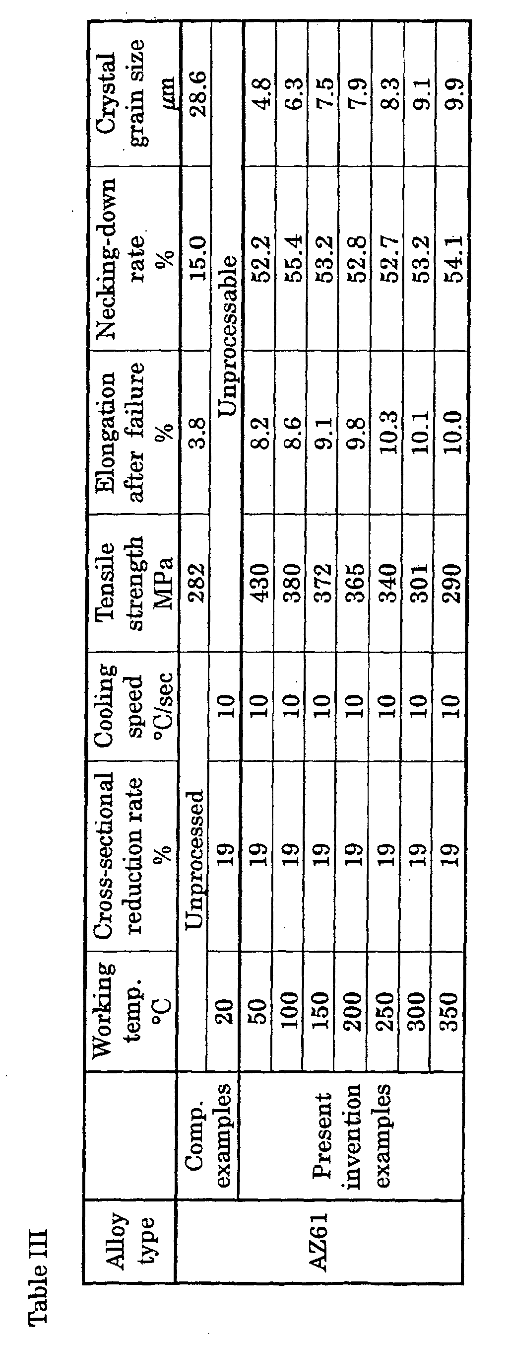
- Table III the characteristics of wire obtained wherein the working temperature was varied are set forth, while in Table IV, the characteristics of wire obtained wherein the cross-sectional reduction rate was varied are.
- the toughness of the extrusion material prior to the drawing process was a low 15% necking-down rate, and 3.8% elongation.
- the present invention examples which went through drawing processes at temperatures of 50°C or more, had necking-down rates of 50% or more and elongations of 8% or more. Their strength, moreover, exceeded that prior to the drawing process; and what with their strength being raised enhanced toughness was achieved.
- Spring-formation was carried out utilizing the wire produced in Embodiments 1 and 2, and the same diameter of extrusion material.
- Spring-forming work to make springs 40 mm in outside diameter was carried out utilizing the 5.0 mm-diameter wire; and the relationship between whether spring-formation was or was not possible, and the average crystal grain size of and the roughness of the material, were investigated.
- Adjustment of the average crystal grain size and adjustment of the surface roughness were carried out principally by adjusting the working temperature during the drawing process.
- the working temperature in the present example was 50 to 200°C.
- the average crystal grain size was found by magnifying the wire cross-sectional structure under a microscope, measuring the grain size of a number of the crystals within the field of view, and averaging the sizes.
- the average crystal grain size was found by magnifying the wire cross-sectional structure under a microscope, measuring the grain size of a number of the crystals within the field of view, and averaging the sizes.
- the axial residual stress in the wire surface was found by X-ray diffraction.
- the post-processing wire diameter was 4.84 to 5.85 mm (5.4 mm in a 19% cross-sectional reduction process; 5.85 to 4.84 mm at 5 to 35% cross-sectional reduction rates).
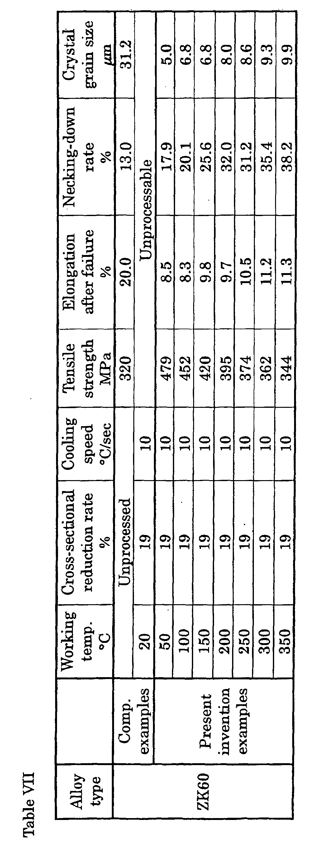
- Table VII the characteristics of wire obtained wherein the working temperature was varied are set forth, while in Table VIII, the characteristics of wire obtained wherein the cross-sectional reduction rate was varied are.
- AZ31 containing 3.0% Al, 1.0% Zn and 0.15% Mn; remainder being Mg and impurities.
- AZ61 containing 6.4% Al, 1.0% Zn and 0.28% Mn; remainder being Mg and impurities.
- ZK60 containing 5.5% Zn and 0.45% Zr; remainder being Mg and impurities.
- the obtained wires were also put into even coils at 1.0 to 5.0 kg respectively on reels. Wire pulled out from the reels had good flexibility in terms of coiling memory, meaning that excellent welds in manual welding, and MIG, TIG and like automatic welding can be expected from the wire.
- wires were produced by carrying out a drawing process at a 100°C working temperature until the material was ⁇ 4.6 mm (10% or greater single-pass formability; 67% total formability).
- the heating temperature of a heater set up in front of the wire die was taken to be the working temperature.
- the speed with which the temperature was elevated to the working temperature was 1 to 10°C/sec, and the wire speed in the drawing process was 2 to 10 m/min. Cooling following the drawing process was carried out by air-blast cooling, and the cooling speed was 0.1°C/sec or more.
- the obtained wires were heat-treated for 15 minutes at 100°C to 350°C.
- the heating temperature was 150°C or more, although the strength dropped somewhat, recovery in elongation and necking-down rates was remarkable, wherein wire in which a balance was struck between strength and toughness was obtained.
- the crystalline structure with the heating temperature being 150°C and 200°C turned out to be a mixed-grain structure of crystal grains 3 ⁇ m or less average grain size, and crystal grains 15 ⁇ m or less (ditto).
- a structure in which the magnitude of the crystal grains was nearly uniform was exhibited; those average grain sizes are as entered in Table XI. Securing 300 MPa or greater strength with average grain size being 5 ⁇ m or less was possible.
- the heating temperature of a heater set up in front of the wire die was taken to be the working temperature of the drawing process.
- the speed with which the temperature was elevated to the working temperature was 2 to 5°C/sec, and the wire speed in the drawing process was 2 to 5 m/min. Cooling following the drawing process was carried out by air-blast cooling, and the cooling speed was 0.1°C/sec or more.
- FIG. 1 An optical micrograph of the structure of the post-heat-treated wire in which the formability was made 23% is presented in Fig. 1.
- the structure proved to be a mixture of crystal grains 3 ⁇ m or less average grain size, and crystal grains 15 ⁇ m or less (ditto), wherein the surface-area percentage of crystal grains 3 ⁇ m or less is approximately 15%.
- the mixed-grain structures in the present embodiment is that in every case the surface-area percentage of crystal grains 3 ⁇ m or less is 10% or more.
- total formability of 30% or more was effective in heightening the strength all the more.
- a drawing process at a 150°C working temperature until the material was ⁇ 5.0 mm (30.6% total formability) was carried out.
- the heating temperature of a heater set up in front of the wire die was taken to be the working temperature.
- the speed with which the temperature was elevated to the working temperature was 2 to 5°C/sec, and the wire speed in the drawing process was 2 m/min.
- Cooling following the drawing process was carried out by air-blast cooling, and the cooling speed was made 0.1°C/sec or more.
- a 15-min. heating treatment at 100°C to 350°C was carried out on the wires after cooling.
- the tensile characteristics of the post-heat-treated wire are indicated in Table XIII.
- the heating temperature was 150°C or more, although the strength dropped somewhat, recovery in elongation and necking-down rates was remarkable, wherein wire in which a balance was struck between strength and toughness was obtained.
- the crystalline structure with the heating temperature being 150°C and 200°C turned out to be a mixed-grain structure of crystal grains 3 ⁇ m or less average grain size, and crystal grains 15 ⁇ m or less (ditto).
- a structure of uniform grain size was exhibited; those grain sizes are as entered in Table XIII. Securing 390 MPa or greater strength with average grain size being 5 ⁇ m or less was possible.
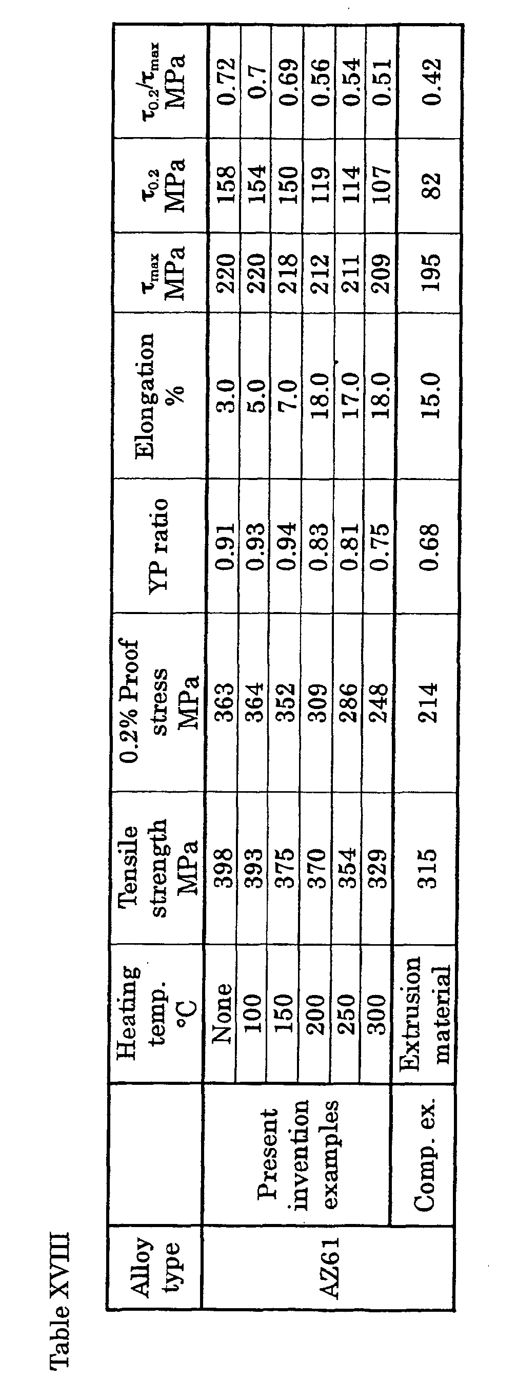
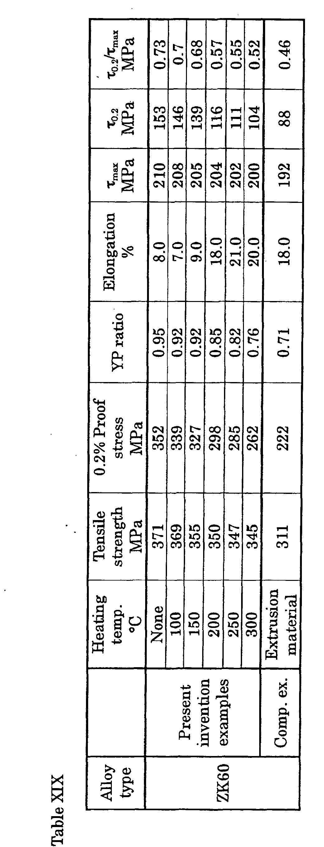
- the YP ratio and torsion yield ratio ⁇ 0.2 / ⁇ max were evaluated for the wire characteristics.
- the YP ratio is 0.2% proof stress/tensile strength.
- the inter-chuck distance in the torsion test was made 100 d ( d : wire diameter); ⁇ 0.2 and ⁇ max were found from the relationship between the torque and the rotational angle reckoned during the test.
- the characteristics of the extrusion material as a comparison material are also tabulated and set forth. Alloy type Heating temp.
- the YP ratios for the present invention examples, on which wiredrawing and heat treatment were performed were 0.75 or larger. It is apparent that among them, with the present invention examples whose YP ratios were controlled to be 0.75 or more but less than 0.90 the percent elongation was large, while the workability was quite good. If even greater strength is sought, it will be found balanced very well with elongation in the examples whose YP ratio is 0.80 or more but less than 0.90.
- the torsion yield ratio ⁇ 0.2 / ⁇ max was less than 0.5 with the extrusion materials in whichever composition, but with those on which wiredrawing and heat treatment were performed, high values of 0.50 or greater were shown. In cases where, with formability being had in mind, elongation is to be secured, it will be understood that a torsion yield ratio ⁇ 0.2 / ⁇ max of 0.50 or more but less than 0.60 would be preferable.
- the speed with which the temperature was elevated to the working temperature was 10°C/sec; the cooling speed was 0.1°C/sec or faster; and the wire speed in the drawing process was 2 m/min.
- the cooling was carried out by air-blast cooling. After that, the filamentous articles obtained underwent a 20-minute heating treatment at a temperature of from 50°C to 350°C, yielding various wires.
- the tensile strength, elongation after failure, necking-down rate, YP ratio, ⁇ 0.2 / ⁇ max , and crystal grain size were investigated.
- the average crystal grain size was found by magnifying the wire cross-sectional structure under a microscope, measuring the grain size of a number of the crystals within the field of view, and averaging the sizes. The results are set forth in Table XX.
- the tensile strength of the ⁇ 5.0 mm extrusion material was 225 MP; its toughness: 38% necking-down rate, 9% elongation; its YP ratio, 0.64; and its ⁇ 0.2 / ⁇ max ratio, 0.55.
- the wire obtained in this embodiment proved to have very fine crystal grains in that, as indicated in Table XX, with a heating temperature of 150°C plus, the crystal grain size was 10 ⁇ m or less, and 5 ⁇ m or less with a 200 to 250°C temperature.
- a 150°C temperature led to a mixed-grain structure of 3 ⁇ m-and-under crystal grains, and 15 ⁇ m-and-over crystal grains, wherein the surface-area percentage of crystal grains 3 ⁇ m or less was 10% or more.
- the length of the wires produced was 1000 times or more their diameter, while the surface roughness R z was 10 ⁇ m or less.
- the axial residual stress in the wire surface was found by X-ray diffraction, wherein the said stress was 80 MPa or less.
- the out-of-round was 0.01 mm or less. The out-of-round was the difference between the maximum and minimum values of the diameter in the same sectional plane through the wire.
- a variety of wires were produced utilizing as a ⁇ 5.0 mm extrusion material an AZ10-alloy magnesium-based alloy containing, in mass %, 1.2% Al, 0.4% Zn and 0.3% Mn, with the remainder being composed of Mg and impurities, by draw-working the extrusion material under a variety of conditions.
- a wire die was used for the drawing process.
- a heater was set up in front of the wire die, and the heating temperature of the heater was taken to be the working temperature.
- the speed with which the temperature was elevated to the working temperature was 10°C/sec, and the wire speed in the drawing process was 2 m/min.
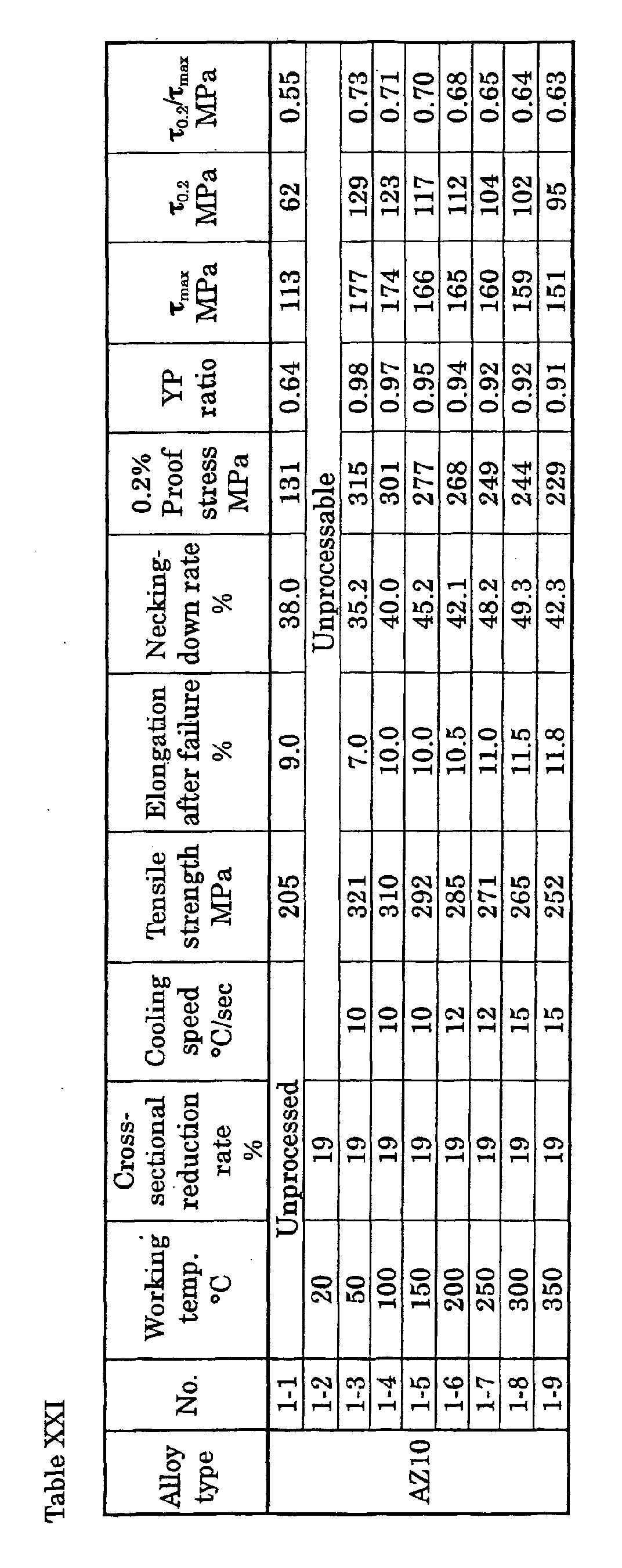
- the characteristics of the obtained wires are set froth in Tables XXI and XXII.
- Table XXI The conditions and results in Table XXI are for the case where the cross-sectional reduction rate was fixed and the working temperature was varied, and in Table XXII, for the case where the working temperature was fixed and the cross-sectional reduction rate was varied.
- the drawing work was a single pass only, and "cross-sectional reduction rate" herein is the total cross-sectional reduction rate.
- the tensile strength of the extrusion material was 205 MPa; its toughness: 38% necking-down rate, 9% elongation.
- Nos. 1-3 through 1-9 which were draw-worked at a temperature of 50°C or more, had a necking-down rate of 30% or greater, and an elongation percentage of 6% or greater.
- these test materials have a high, 250 MPa or greater tensile strength, 0.90 or greater YP ratio, and 0.60 or greater ⁇ 0.2 / ⁇ max ratio, and that in them improved strength without appreciably degraded toughness was achieved. Nos.
- the obtained wires in either Table XXI or Table XXII were of length 1000 times or more their diameter, and were capable of being repetitively worked in multipass drawing.
- the surface roughness R z was 10 ⁇ m or less.
- the axial residual stress in the wire surface was found by X-ray diffraction, wherein the said stress was 80 MPa or less.
- the out-of-round was 0.01 mm or less. The out-of-round was the difference between the maximum and minimum values of the diameter in the same sectional plane through the wire.
- the tensile strength of the AS41-alloy extrusion material was 259 MPa, and the 0.2% proof stress, 151 MPa; while the YP ratio was a low 0.58. Furthermore, necking-down rate was 19.5%, and elongation, 9.5%.
- the tensile strength of the AM60-alloy extrusion material was 265 MPa, and the 0.2% proof stress, 160 MPa; while the YP ratio was a low 0.60.
- ⁇ 5.0 mm extrusion materials Utilizing as ⁇ 5.0 mm extrusion materials an AS41 magnesium alloy containing, in mass %, 4.2% Al, 0.50% Mn and 1.1% Si, with the remainder being composed of Mg and impurities, and an AM60 magnesium alloy containing 6.1% Al and 0.44% Mn, with the remainder being composed of Mg and impurities, a process in which the materials were drawn at a 19% cross-sectional reduction rate through a wire die until they were ⁇ 4.5 mm was carried out at a working temperature of 150°C. The cooling speed following the process was 10°C/sec. The wires obtained in this instance were heated for 15 minutes at 80°C and 200°C, and the room-temperature tensile characteristics and crystal grain size were evaluated.
- the tensile strength, 0.2% proof stress, and YP ratio improved significantly following the wiredrawing process. Viewed in terms of mechanical properties, with a working temperature of 80°C the post-drawn, heat-treated material underwent no major changes in post-drawing characteristics. It is evident that with a temperature of 200°C, elongation after failure and necking-down rate rose significantly. The tensile strength, 0.2% proof stress, and YP ratio may have fallen compared with as-drawn wire material, but greatly exceeded the tensile strength, 0.2% proof stress, and YP ratio of the original extrusion material.
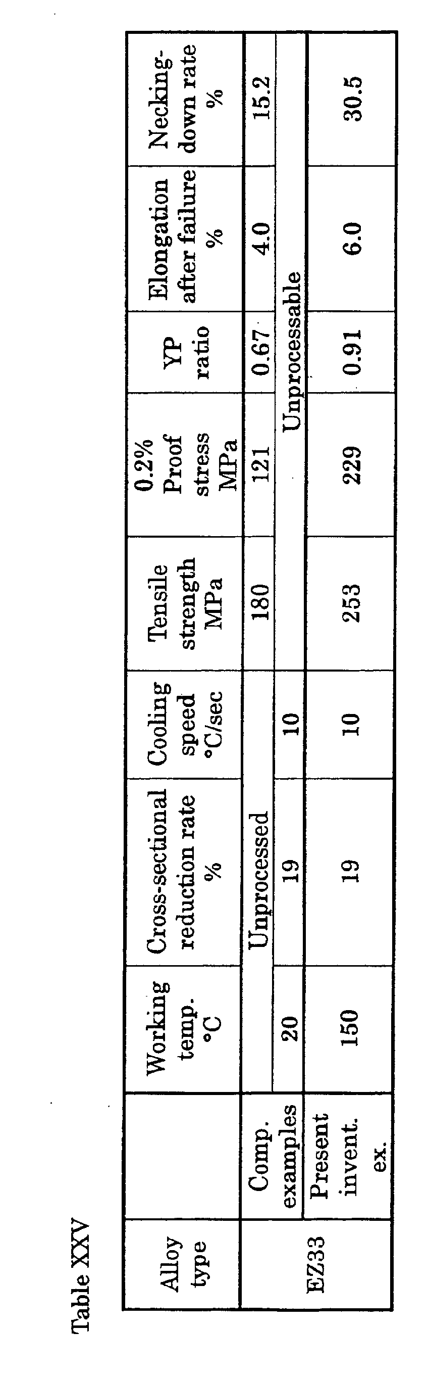
- a process was carried out in which an EZ33 magnesium-alloy casting material containing, in mass %, 2.5% Zn, 0.6% Zr, and 2.9% RE, with the remainder being composed of Mg and impurities, was by hot-casting rendered into a ⁇ 5.0 mm rod material, which was drawn at a 19% cross-sectional reduction rate through a wire die until it was ⁇ 4.5 mm.
- the process conditions therein and the characteristics of the wire produced are set forth in Table XXV.
- didymium was used as the RE.
- the tensile strength of the EZ33-alloy extrusion material was 180 MPa, and the 0.2% proof stress, 121 MPa; while the YP ratio was a low 0.67. Furthermore, necking-down rate was 15.2%, and elongation, 4.0%.
- the tensile strength, 0.2% proof stress, and YP ratio improved significantly following the wiredrawing process. Viewed in terms of mechanical properties, with a working temperature of 80°C the post-drawn, heat-treated material underwent no major changes in post-drawing characteristics. It is evident that with a temperature of 200°C, elongation after failure and necking-down rate rose significantly. The tensile strength, 0.2% proof stress, and YP ratio may have fallen compared with as-drawn wire material, but greatly exceeded the tensile strength, 0.2% proof stress, and YP ratio of the original extrusion material.
- the crystal grain size obtained in this embodiment with a heating temperature of 200°C was 5 ⁇ m or less, in very fine crystal grains. Furthermore, the length of the wire produced was 1000 times or more its diameter; while the surface roughness R z was 10 ⁇ m or less, the axial residual stress was 80 MPa or less, and the out-of-round was 0.01 mm or less.
- the tensile strength of the AS21-alloy extrusion material was 215 MPa, and the 0.2% proof stress, 141 MPa; while the YP ratio was a low 0.66.
- the material that was heated to a temperature of 150°C and underwent the drawing process had a necking-down rate of over 40% and an elongation percentage of over 6%, and had a high tensile strength of over 250 MPa, and a YP ratio of over 0.9, wherein it is evident that the strength could be improved without appreciably sacrificing toughness. Meanwhile, the drawing process at a room temperature of 20°C was unworkable due to the wire snapping.
- the crystal grain size obtained in this embodiment with a heating temperature of 200°C was 5 ⁇ m or less, in very fine crystal grains. Furthermore, the length of the wire produced was 1000 times or more its diameter; while the surface roughness R z was 10 ⁇ m or less, the axial residual stress was 80 MPa or less, and the out-of-round was 0.01 mm or less.
- a wire manufacturing method according to the present invention enables drawing work on magnesium alloys that conventionally had been problematic, and lends itself to producing magnesium-based alloy wire excelling in strength and toughness.
Landscapes
- Chemical & Material Sciences (AREA)
- Engineering & Computer Science (AREA)
- Mechanical Engineering (AREA)
- Materials Engineering (AREA)
- Metallurgy (AREA)
- Organic Chemistry (AREA)
- Physics & Mathematics (AREA)
- Thermal Sciences (AREA)
- Crystallography & Structural Chemistry (AREA)
- Metal Extraction Processes (AREA)
- Forging (AREA)
- Conductive Materials (AREA)
Abstract
Description



| Alloy type | Crystal grain size µm | Surface roughness µm | Spring-forming possible/not poss.: + not: - | |
| AZ31 | Present invention examples | 5.0 | 5.3 | + |
| 6.5 | 4.7 | + | ||
| 7.2 | 6.7 | + | ||
| 7.9 | 6.4 | + | ||
| 8.7 | 8.8 | + | ||
| 9.2 | 7.8 | + | ||
| 9.8 | 8.9 | + | ||
| Comp. examples | 28.5 | 18.3 | - | |
| 29.3 | 12.5 | - | ||
| AZ61 | Present invention examples | 4.8 | 5.1 | + |
| 6.3 | 5.3 | + | ||
| 7.5 | 6.8 | + | ||
| 7.9 | 5.3 | + | ||
| 8.3 | 8.9 | + | ||
| 9.1 | 7.8 | + | ||
| 9.9 | 8.8 | + | ||
| Comp. examples | 29.6 | 18.3 | - | |
| 27.5 | 12.5 | - |
| Alloy type | Annealing temp. °C | Tensile strength MPa | Elongation after failure % | Necking-down rate % | |
| AZ61 | Comp. examples | None | 460 | 6.0 | 15.0 |
| Present invention examples | 100 | 430 | 25.0 | 45.0 | |
| 200 | 382 | 22.0 | 48.0 | ||
| 300 | 341 | 23.0 | 40.0 | ||
| 400 | 310 | 20.0 | 35.0 |

| Alloy type | Crystal grain size µm | Surface roughness µm | Spring-forming possible/not poss.: + not: - | |
| ZK60 | Present invention examples | 4.8 | 5.0 | + |
| 6.3 | 6.8 | + | ||
| 7.5 | 6.8 | + | ||
| 7.9 | 8.0 | + | ||
| 8.3 | 8.6 | + | ||
| 9.1 | 9.3 | + | ||
| 9.9 | 9.9 | + | ||
| Comp. examples | 30.2 | 19.2 | - | |
| 26.8 | 13.7 | - |
| Alloy type | Mfr. tech. | Tensile strength MPa | Elongation % | Necking-down rate % | Out-of-round mm | Surface roughness µm |
| AZ31 | Wire draw. | 340 | 50 | 9 | 0.005 | 4.8 |
| AZ61 | " | 430 | 21 | 9 | 0.005 | 5.2 |
| AZ91 | " | 450 | 18 | 8 | 0.008 | 6.2 |
| ZK60 | " | 480 | 18 | 9 | 0.007 | 4.3 |
| AZ31 | Extrusion | 260 | 35 | 15 | 0.022 | 12.8 |
| AZ61 | " | 285 | 35 | 15 | 0.015 | 11.2 |
| AZ91 | " | 320 | 13 | 9 | 0.018 | 15.2 |
| ZK60 | " | 320 | 13 | 20 | 0.021 | 18.3 |
| Alloy type | Heating temp. °C | Tensile strength MPa | Elongation after failure % | Necking-down rate % | Crystal grain size µm | |
| AZ31 | Reference examples | 50 | 423 | 2.0 | 10.2 | 22.5 |
| 80 | 418 | 4.0 | 14.3 | 21.2 | ||
| Present invention examples | 150 | 365 | 10.0 | 31.2 | Mixed-grain | |
| 200 | 330 | 18.0 | 45.0 | Mixed-grain | ||
| 250 | 310 | 18.0 | 57.5 | 4.0 | ||
| 300 | 300 | 19.0 | 51.3 | 5.0 | ||
| Ref. ex. | 350 | 270 | 21.0 | 47.1 | 10.0 |
| Alloy type | Formability % | Tensile strength MPa | Elongation after failure % | Necking-down rate % | Crystal grain size µm | |
| AZ31 | Ref. ex. | 9.8 | 280 | 9.5 | 41.0 | 18.2 |
| Pres. invent. ex. | 15.6 | 302 | 18.0 | 47.2 | Mixed-grain | |
| 23.0 | 305 | 17.0 | 45.9 | Mixed-grain | ||
| 34.0 | 325 | 18.0 | 44.8 | Mixed-grain | ||
| 43.8 | 328 | 19.0 | 47.2 | Mixed-grain | ||
| 66.9 | 330 | 18.0 | 45.0 | Mixed-grain |
| Alloy type | Heating temp. °C | Tensile strength MPa | Elongation after failure % | Necking-down rate % | Crystal grain size µm | |
| ZK60 | Reference examples | 50 | 525 | 3.2 | 8.5 | 17.5 |
| 80 | 518 | 5.5 | 10.2 | 16.8 | ||
| Present invention examples | 150 | 455 | 10.0 | 32.2 | Mixed-grain | |
| 200 | 445 | 15.5 | 35.5 | Mixed-grain | ||
| 250 | 420 | 17.5 | 33.2 | 3.2 | ||
| 300 | 395 | 16.8 | 34.5 | 4.8 | ||
| Ref. ex. | 350 | 360 | 18.9 | 35.5 | 9.7 |
| Alloy type | Heating temp. °C | Tensile strength MPa | 0.2% Proof stress MPa | YP ratio | τmax MPa | τ0.2 MPa | τ0.2/τmax MPa | |
| AZ31 | Present invent. ex. | 100 | 345 | 333 | 0.96 | 188 | 136 | 0.72 |
| 200 | 331 | 311 | 0.94 | 186 | 133 | 0.72 | ||
| 300 | 309 | 282 | 0.91 | 182 | 115 | 0.63 | ||
| Comp. ex. | Extrusion material | 268 | 185 | 0.69 | 166 | 78 | 0.47 |
| Alloy type | Heating temp. °C | Tensile strength MPa | 0.2% Proof stress MPa | YP ratio | τmax MPa | τ0.2 MPa | τ0.2/τmax MPa | |
| ZK60 | Present invent. ex. | 100 | 376 | 359 | 0.96 | 205 | 147 | 0.72 |
| 200 | 373 | 358 | 0.96 | 210 | 138 | 0.66 | ||
| 300 | 364 | 352 | 0.97 | 214 | 130 | 0.61 | ||
| Comp. ex. | Extrusion material | 311 | 222 | 0.71 | 192 | 88 | 0.46 |




| Alloy type | Working temp. °C | Tensile . strength MPa | 0.2% Pf Str. MPa | YP ratio | Elong. % | Necking-down rate % | Crystal size µm | |
| AS41 | Comp. ex. | None | 365 | 335 | 0.92 | 9.0 | 35.3 | 20.5 |
| 80 | 363 | 332 | 0.91 | 9.0 | 35.5 | 20.3 | ||
| Pres. inv. ex. | 200 | 330 | 283 | 0.86 | 18.5 | 48.2 | 3.5 | |
| Comp. ex. | Extrusion material | 259 | 151 | 0.58 | 9.5 | 19.5 | 21.5 | |
| AM60 | Comp. ex. | None | 372 | 344 | 0.92 | 8.0 | 32.5 | 19.6 |
| 80 | 370 | 335 | 0.91 | 9.0 | 33.5 | 20.2 | ||
| Pres. inv. ex. | 200 | 329 | 286 | 0.87 | 17.5 | 49.5 | 3.8 | |
| Comp. ex. | Extrusion material | 265 | 160 | 0.60 | 6.0 | 19.5 | 19.5 |
| Alloy type | Working temp. °C | Tensile strength MPa | 0.2% Pf. str. MPa | YP ratio | Elong. % | Necking-down rate % | Crystal grain size µm | |
| EZ33 | Comp. ex. | None | 253 | 229 | 0.91 | 6.0 | 30.5 | 23.4 |
| 80 | 251 | 226 | 0.90 | 7.0 | 31.2 | 21.6 | ||
| Pres. inv. ex. | 200 | 225 | 195 | 0.87 | 16.5 | 42.3 | 4.3 | |
| Comp. ex. | Casting + cast.mtr. | 180 | 121 | 0.67 | 4.0 | 15.2 | 22.5 |

| Alloy type | Working temp. °C | Tensile strength MPa | 0.2% Pf. str. MPa | YP ratio | Elong. % | Necking-down rate % | Crystal grain size µm | |
| AS21 | Comp. ex. | None | 325 | 295 | 0.91 | 9.0 | 45.1 | 22.1 |
| 80 | 322 | 293 | 0.91 | 9.5 | 46.2 | 20.5 | ||
| Pres. inv. ex. | 200 | 303 | 263 | 0.87 | 18.0 | 52.5 | 3.8 | |
| Comp. ex. | Extrusion mtr. | 215 | 141 | 0.66 | 10.0 | 35.5 | 23.4 |
| Alloy type | Heating temp. °C | Fatigue strength Mpa | Avg. crystal grain size µm | Residual stress MPa |
| AZ31 | 100 | 80 | - | 98 |
| 150 | 110 | 2.2 | 6 | |
| 200 | 105 | 2.8 | -1 | |
| 250 | 105 | 3.3 | 0 | |
| 300 | 95 | 6.5 | 2 | |
| 350 | 95 | 12.2 | -3 |
| Alloy type | Heating temp. °C | Fatigue strength MPa | Avg. crystal gram size µm | Residual stress MPa |
| AZ61 | 100 | 80 | ― | 92 |
| 150 | 120 | 2.1 | 5 | |
| 200 | 115 | 2.9 | 3 | |
| 250 | 115 | 3.1 | -3 | |
| 300 | 105 | 5.9 | 2 | |
| 350 | 105 | 9.9 | -1 |
| Alloy type | Heating temp. °C | Fatigue strength MPa | Avg. crystal grain size µm | Residual stress MPa |
| AS41 | 100 | 80 | - | 95 |
| 150 | 115 | 2.3 | 6 | |
| 200 | 110 | 2.5 | -2 | |
| 250 | 110 | 3.4 | 0 | |
| 300 | 100 | 6.2 | 1 | |
| 350 | 100 | 10.2 | -1 |
| Alloy type | Heating temp. °C | Fatigue strength MPa | Avg. crystal grain size µm | Residual stress MPa |
| AM60 | 100 | 80 | - | 96 |
| 150 | 115 | 2.0 | 5 | |
| 200 | 110 | 2.3 | 3 | |
| 250 | 110 | 3.2 | -1 | |
| 300 | 100 | 6.1 | -2 | |
| 350 | 100 | 10.5 | 0 |
| Alloy type | Heating temp. °C | Fatigue strength MPa | Avg. crystal grain size µm | Residual stress MPa |
| ZK60 | 100 | 80 | - | 96 |
| 150 | 120 | 2.2 | 6 | |
| 200 | 115 | 2.7 | 2 | |
| 250 | 115 | 3.3 | 0 | |
| 300 | 105 | 6.2 | 1 | |
| 350 | 105 | 9.7 | -1 |
Claims (66)
- Magnesium-based alloy wire containing, in mass %, 0.1 to 12.0% Al, and 0.1 to 1.0% Mn, the magnesium-based alloy wire characterized in that:its diameter d is 0.1 mm or more and 10.0 mm or less;its length L is 1000 d or more;its tensile strength is 250 MPa or more;its necking-down rate is 15% or more; andits elongation is 6% or more.
- Magnesium-based alloy wire as set forth in claim 1, characterized in that it contains, in mass %, 0.1 to less than 2.0% Al, and 0.1 to 1.0% Mn, and in that its necking-down rate is 40% or more and its elongation is 12% or more.
- Magnesium-based alloy wire as set forth in claim 1, characterized in that it contains, in mass %, 0.1 to less than 2.0% Al, and 0.1 to 1.0% Mn, and in that its necking-down rate is 30% or more and its elongation is 6% or more and les than 12%.
- Magnesium-based alloy wire as set forth in claim 1, characterized in that it contains, in mass %, 2.0 to 12.0% Al, and 0.1 to 1.0% Mn, and in that its tensile strength is 300 MPa or more.
- Magnesium-based alloy wire containing, in mass %, 0.1 to 12.0% Al, and 0.1 to 1.0% Mn, the magnesium-based alloy wire characterized in that:its diameter d is 1.0 to 10.0 mm, andits length L is 1000d or more; and in thatits fatigue strength when a repeat push-pull stress amplitude is applied 1×10⁷ times is 105 MPa or more.
- Magnesium-based alloy wire containing, in mass %, 0.1 to 12.0% Al, and 0.1 to 1.0% Mn, the magnesium-based alloy wire characterized in that:its YP ratio is 0.75 or more.
- Magnesium-based alloy wire as set forth in claim 6, characterized in that it contains, in mass %, 0.1 to less than 2.0% Al, and 0.1 to 1.0% Mn, and in that its YP ratio is 0.75 or more and less than 0.90.
- Magnesium-based alloy wire as set forth in claim 6, characterized in that it contains, in mass %, 0.1 to less than 2.0% Al, and 0.1 to 1.0% Mn, and in that its YP ratio is 0.90 or more.
- Magnesium-based alloy wire as set forth in claim 6, characterized in that it contains, in mass %, 2.0 to 12.0% Al, and 0.1 to 1.0% Mn, and in that its YP ratio is 0.75 or more and less than 0.90.
- Magnesium-based alloy wire as set forth in claim 6, characterized in that it contains, in mass %, 2.0 to 12.0% Al, and 0.1 to 1.0% Mn, and in that its YP ratio is 0.90 or more.
- Magnesium-based alloy wire containing, in mass %, 0.1 to 12.0% Al, and 0.1 to 1.0% Mn, the magnesium-based alloy wire characterized in that:the ratio τ0.2/τmax of its 0.2% offset strength τ0.2 to its maximum shear stress τmax in a torsion test is 0.50 or more.
- Magnesium-based alloy wire as set forth in claim 11, characterized in that it contains, in mass %, 0.1 to less than 2.0% Al, and 0.1 to 1.0% Mn, and in that the ratio τ0.2/τmax of its 0.2% offset strength τ0.2 to its maximum shear stress τmax in a torsion test is 0.50 or more and less than 0.60.
- Magnesium-based alloy wire as set forth in claim 11, characterized in that it contains, in mass %, 0.1 to less than 2.0% Al, and 0.1 to 1.0% Mn, and in that the ratio τ0.2/τmax of its 0.2% offset strength τ0.2 to its maximum shear stress τmax in a torsion test is 0.60 or more.
- Magnesium-based alloy wire as set forth in claim 11, characterized in that it contains, in mass %, 2.0 to 12.0% Al, and 0.1 to 1.0% Mn, and in that the ratio τ0.2/τmax of its 0.2% offset strength τ0.2 to its maximum shear stress τmax in a torsion test is 0.50 or more and less than 0.60.
- Magnesium-based alloy wire as set forth in claim 11, characterized in that it contains, in mass %, 2.0 to 12.0% Al, and 0.1 to 1.0% Mn, and in that the ratio τ0.2/τmax of its 0.2% offset strength τ0.2 to its maximum shear stress τmax in a torsion test is 0.60 or more.
- Magnesium-based alloy wire containing, in mass %, 0.1 to 12.0% Al, and 0.1 to 1.0% Mn, the magnesium-based alloy wire characterized in that:the crystal grain size of the alloy composing the wire is 10 µm or less.
- Magnesium-based alloy wire as set forth in claim 16, characterized in that it incorporates, in mass %, 0.1 to less than 2.0% Al.
- Magnesium-based alloy wire as set forth in claim 16, characterized in that it incorporates, in mass %, 2.0 to 12.0% Al.
- Magnesium-based alloy wire as set forth in claim 16, characterized in that the crystal grain size of the alloy composing the wire is 5 µm or less.
- Magnesium-based alloy wire containing, in mass %, 0.1 to 12.0% Al, and 0.1 to 1.0% Mn, the magnesium-based alloy wire characterized in that:the crystal grains of the alloy composing the wire are sized in fine crystal grains and coarse crystal grains in a mixed-grain structure.
- Magnesium-based alloy wire as set forth in claim 20, characterized in that the fine crystal grains are 3 µm or less in average crystal grain size, and the coarse crystal grains are 15 µm or more in average crystal grain size.
- Magnesium-based alloy wire as set forth in claim 20, characterized in that the surface-area percentage of the crystal grains having an average crystal grain size of 3 µm or less is 10% or more of the whole.
- Magnesium-based alloy wire as set forth in any of claims 20 through 22, characterized in that it incorporates, in mass %, 0.1 to less than 2.0% Al.
- Magnesium-based alloy wire as set forth in any of claims 20 through 22, characterized in that it incorporates, in mass %, 2.0 to 12.0% Al.
- Magnesium-based alloy wire containing, in mass %, 0.1 to 12.0% Al, and 0.1 to 1.0% Mn, the magnesium-based alloy wire characterized in that:the surface roughness of the wire superficially is Rz ≤ 10 µm.
- Magnesium-based alloy wire containing, in mass %, 0.1 to 12.0% Al, and 0.1 to 1.0% Mn, the magnesium-based alloy wire characterized in that:the axial residual stress superficially in the wire is 80 MPa or less.
- Magnesium-based alloy wire as set forth in claim 26, characterized in that the axial residual stress superficially in the wire is 10 MPa or less.
- Magnesium-based alloy wire as set forth in any of claims 1 through 27, characterized in further containing 1 or more elements selected from Zn, in 0.5 to 2.0 mass %, and Si, in 0.3 to 2.0 mass %.
- Magnesium-based alloy wire as set forth in any of claims 1 through 27, characterized in further containing Zn, in 0.5 to 2.0 mass %, with the remainder being Mg and impurities.
- Magnesium-based alloy wire containing, in mass %, 1.0 to 10.0% Zn, and 0.4 to 2.0% Zr, the magnesium-based alloy wire characterized in that:its diameter d is 0.1 mm or more and 10.0 mm or less;its length L is 1000 d or more;its tensile strength is 300 MPa or more;its necking-down rate is 15% or more; andits elongation is 6% or more.
- Magnesium-based alloy wire containing, in mass %, 1.0 to 10.0% Zn, and 0.4 to 2.0% Zr, the magnesium-based alloy wire characterized in that:its diameter d is 1.0 to 10.0 mm, andits length L is 1000d or more; and in thatits fatigue strength when a repeat push-pull stress amplitude is applied 1×10⁷ times is 105 MPa or more.
- Magnesium-based alloy wire containing, in mass %, 1.0 to 10.0% Zn, and 0.4 to 2.0% Zr, the magnesium-based alloy wire characterized in that:the crystal grain size of the alloy composing the wire is 10 µm or less.
- Magnesium-based alloy wire as set forth in claim 32, characterized in that the crystal grain size of the alloy composing the wire is 5 µm or less.
- Magnesium-based alloy wire containing, in mass %, 1.0 to 10.0% Zn, and 0.4 to 2.0% Zr, the magnesium-based alloy wire characterized in that:the crystal grains of the alloy composing the wire are sized in fine crystal grains and coarse crystal grains in a mixed-grain structure.
- Magnesium-based alloy wire as set forth in claim 34, characterized in that the fine crystal grains are 3 µm or less in average crystal grain size, and the coarse crystal grains are 15 µm or more in average crystal grain size.
- Magnesium-based alloy wire as set forth in claim 35, characterized in that the surface-area percentage of the crystal grains having an average crystal grain size of 3 µm or less is 10% or more of the whole.
- Magnesium-based alloy wire containing, in mass %, 1.0 to 10.0% Zn, and 0.4 to 2.0% Zr, the magnesium-based alloy wire characterized in that:the surface roughness of the wire superficially is Rz ≤ 10 µm.
- Magnesium-based alloy wire containing, in mass %, 1.0 to 10.0% Zn, and 0.4 to 2.0% Zr, the magnesium-based alloy wire characterized in that:the axial residual stress superficially in the wire is 80 MPa or less.
- Magnesium-based alloy wire as set forth in claim 38, characterized in that the axial residual stress superficially in the wire is 10 MPa or less.
- Magnesium-based alloy wire containing, in mass %, 1.0 to 10.0% Zn, and 0.4 to 2.0% Zr, the magnesium-based alloy wire characterized in that:its YP ratio is 0.90 or more.
- Magnesium-based alloy wire containing, in mass %, 1.0 to 10.0% Zn, and 0.4 to 2.0% Zr, the magnesium-based alloy wire characterized in that:its YP ratio is 0.75 or more and less than 0.90.
- Magnesium-based alloy wire containing, in mass %, 1.0 to 10.0% Zn, and 0.4 to 2.0% Zr, the magnesium-based alloy wire characterized in that:the ratio τ0.2/τmax of its 0.2% offset strength τ0.2 to its maximum shear stress τmax in a torsion test is 0.60 or more.
- Magnesium-based alloy wire containing, in mass %, 1.0 to 10.0% Zn, and 0.4 to 2.0% Zr, the magnesium-based alloy wire characterized in that:the ratio τ0.2/τmax of its 0.2% offset strength τ0.2 to its maximum shear stress τmax in a torsion test is 0.50 or more and less than 0.60.
- Magnesium-based alloy wire as set forth in any of claims 30 through 43, characterized in further containing 0.5 to 2.0% Mn..
- Magnesium-based alloy wire containing, in mass %, 1.0 to 10.0% Zn, and 1.0 to 3.0% rare earth element(s), the magnesium-based alloy wire characterized in that:its diameter d is 0.1 mm or more and 10.0 mm or less;its length L is 1000 d or more;its tensile strength is 220 MPa or more;its necking-down rate is 15% or more; andits elongation is 6% or more.
- Magnesium-based alloy wire containing, in mass %, 1.0 to 10.0% Zn, and 1.0 to 3.0% rare earth element(s), the magnesium-based alloy wire characterized in that:the crystal grain size of the alloy composing the wire is 10 µm or less.
- Magnesium-based alloy wire as set forth in claim 46, characterized in that the crystal grain size of the alloy composing the wire is 5 µm or less.
- Magnesium-based alloy wire containing, in mass %, 1.0 to 10.0% Zn, and 1.0 to 3.0% rare earth element(s), the magnesium-based alloy wire characterized in that:the surface roughness of the wire superficially is Rz ≤ 10 µm.
- Magnesium-based alloy wire containing, in mass %, 1.0 to 10.0% Zn, and 1.0 to 3.0% rare earth element(s), the magnesium-based alloy wire characterized in that:the axial residual stress superficially in the wire is 80 MPa or less.
- Magnesium-based alloy wire containing, in mass %, 1.0 to 10.0% Zn, and 1.0 to 3.0% rare earth element(s), the magnesium-based alloy wire characterized in that:its YP ratio is 0.90 or more.
- Magnesium-based alloy wire containing, in mass %, 1.0 to 10.0% Zn, and 1.0 to 3.0% rare earth element(s), the magnesium-based alloy wire characterized in that:its YP ratio is 0.75 or more and less than 0.90.
- Magnesium-based alloy wire containing, in mass %, 1.0 to 10.0% Zn, and 1.0 to 3.0% rare earth element(s), the magnesium-based alloy wire characterized in that:its 0.2% offset strength τ0.2 in a torsion test is 165 MPa or more.
- Magnesium-based alloy wire as set forth in any of claims 1 through 52, characterized in that the wire in cross-sectional form is a non-circular section.
- Magnesium-based alloy wire as set forth in any of claims 1 through 52, characterized in being welding wire whose diameter is 0.8 to 4.0 mm.
- Magnesium-based alloy wire as set forth in any of claims 1 through 52 and 54, characterized in that the out-of-round of the wire is 0.01 mm or less.
- A magnesium-based alloy spring characterized in being the magnesium-based alloy wire as set forth in any of claims 1 through 53 and 55, worked into a spring.
- A method of manufacturing magnesium-based alloy wire, characterized in being provided with:a step of preparing, as a raw-material parent metal, a magnesium-based alloy composed of any of the chemical components in (A) through (E) below:(A) magnesium-based alloy parent metals containing, in mass %: 0.1 to 12.0% Al, and 0.1 to 1.0% Mn;(B) magnesium-based alloy parent metals containing, in mass %: 0.1 to 12.0% Al, and 0.1 to 1.0% Mn; and furthermore containing one or more elements selected from 0.5 to 2.0% Zn, and 0.3 to 2.0% Si;(C) magnesium-based alloy parent metals containing, in mass %: 1.0 to 10.0% Zn, and 0.4 to 2.0% Zr;(D) magnesium-based alloy parent metals containing, in mass %: 1.0 to 10.0% Zn, and 0.4 to 2.0% Zr; and furthermore containing 0.5 to 2.0% Mn; and(E) magnesium-based alloy parent metals containing, in mass %: 1.0 to 10.0% Zn, and 1.0 to 3.0% rare-earth element(s); anda processing step of drawing the raw-material parent metal to work it into wire form.
- A magnesium-based-alloy wire manufacturing method as set forth in claim 57, characterized in that the working temperature in the drawing process is 50°C or more and 200°C or less.
- A magnesium-based-alloy wire manufacturing method as set forth in claim 57, characterized in that cross-sectional reduction rate in one cycle of the drawing process is 10% or more.
- A magnesium-based-alloy wire manufacturing method as set forth in claim 57, characterized in that total cross-sectional reduction rate in the drawing process is 15% or more.
- A magnesium-based-alloy wire manufacturing method as set forth in claim 57, characterized in that wire speed in the drawing process is 1 m/min or more.
- A magnesium-based-alloy wire manufacturing method as set forth in claim 57, characterized in that speed of temperature elevation to the drawing process temperature is 1°C/sec to 100°C/sec.
- A magnesium-based-alloy wire manufacturing method as set forth in claim 57, characterized in that the drawing process is carried out with a wire die or roller dies.
- A magnesium-based-alloy wire manufacturing method as set forth in claim 57, characterized in that the drawing process is carried out in multiple stages utilizing a plurality of wire dies or roller dies.
- A magnesium-based-alloy wire manufacturing method as set forth in claim 57, characterized in that after the drawing process has been performed, the obtained wire-form article is heated at a temperature of 100°C or more and 300°C or less.
- A magnesium-based-alloy wire manufacturing method as set forth in claim 57, characterized in that the drawing process is carried out at less than 50°C.
Priority Applications (1)
| Application Number | Priority Date | Filing Date | Title |
|---|---|---|---|
| EP09007941.9A EP2113579B1 (en) | 2001-06-05 | 2002-05-16 | Magnesium base alloy wire |
Applications Claiming Priority (13)
| Application Number | Priority Date | Filing Date | Title |
|---|---|---|---|
| JP2001170161 | 2001-06-05 | ||
| JP2001170161 | 2001-06-05 | ||
| JP2001287806 | 2001-09-20 | ||
| JP2001287806 | 2001-09-20 | ||
| JP2001398168 | 2001-12-27 | ||
| JP2001398168 | 2001-12-27 | ||
| JP2002027376 | 2002-02-04 | ||
| JP2002027376 | 2002-02-04 | ||
| JP2002027310 | 2002-02-04 | ||
| JP2002027310 | 2002-02-04 | ||
| JP2002092965A JP3592310B2 (en) | 2001-06-05 | 2002-03-28 | Magnesium-based alloy wire and method of manufacturing the same |
| JP2002092965 | 2002-03-28 | ||
| PCT/JP2002/004759 WO2002099148A1 (en) | 2001-06-05 | 2002-05-16 | Magnesium base alloy wire and method for production thereof |
Related Child Applications (2)
| Application Number | Title | Priority Date | Filing Date |
|---|---|---|---|
| EP09007941.9A Division EP2113579B1 (en) | 2001-06-05 | 2002-05-16 | Magnesium base alloy wire |
| EP09007941.9 Division-Into | 2009-06-17 |
Publications (3)
| Publication Number | Publication Date |
|---|---|
| EP1400605A1 true EP1400605A1 (en) | 2004-03-24 |
| EP1400605A4 EP1400605A4 (en) | 2007-06-06 |
| EP1400605B1 EP1400605B1 (en) | 2010-09-29 |
Family
ID=27554947
Family Applications (2)
| Application Number | Title | Priority Date | Filing Date |
|---|---|---|---|
| EP02776537A Expired - Lifetime EP1400605B1 (en) | 2001-06-05 | 2002-05-16 | Magnesium base alloy wire and method for production thereof |
| EP09007941.9A Expired - Lifetime EP2113579B1 (en) | 2001-06-05 | 2002-05-16 | Magnesium base alloy wire |
Family Applications After (1)
| Application Number | Title | Priority Date | Filing Date |
|---|---|---|---|
| EP09007941.9A Expired - Lifetime EP2113579B1 (en) | 2001-06-05 | 2002-05-16 | Magnesium base alloy wire |
Country Status (9)
| Country | Link |
|---|---|
| US (3) | US8308878B2 (en) |
| EP (2) | EP1400605B1 (en) |
| JP (1) | JP3592310B2 (en) |
| KR (2) | KR100612538B1 (en) |
| CN (2) | CN100467645C (en) |
| CA (1) | CA2448052A1 (en) |
| DE (1) | DE60237820D1 (en) |
| TW (1) | TWI293986B (en) |
| WO (1) | WO2002099148A1 (en) |
Cited By (2)
| Publication number | Priority date | Publication date | Assignee | Title |
|---|---|---|---|---|
| EP1640622A4 (en) * | 2003-06-19 | 2006-10-18 | Sumitomo Sei Steel Wire Corp | MAGNESIUM ALLOY SCREWS AND PROCESS FOR PRODUCING THE SAME |
| US20130195711A1 (en) * | 2010-10-15 | 2013-08-01 | Nhk Spring Co., Ltd. | High-strength magnesium alloy wire rod, production method therefor, high-strength magnesium alloy part, and high-strength magnesium alloy spring |
Families Citing this family (32)
| Publication number | Priority date | Publication date | Assignee | Title |
|---|---|---|---|---|
| JP2004027300A (en) * | 2002-06-26 | 2004-01-29 | Daido Steel Co Ltd | Manufacturing method of magnesium alloy rod wire |
| JP4332889B2 (en) * | 2003-05-30 | 2009-09-16 | 住友電気工業株式会社 | Method for producing magnesium-based alloy compact |
| CN100552241C (en) * | 2003-06-19 | 2009-10-21 | 住友电气工业株式会社 | Magnesium-based alloy screw and manufacturing method thereof |
| JP4780600B2 (en) * | 2004-11-17 | 2011-09-28 | 三菱アルミニウム株式会社 | Magnesium alloy sheet excellent in deep drawability and manufacturing method thereof |
| JP4862983B2 (en) * | 2005-03-22 | 2012-01-25 | 住友電気工業株式会社 | Magnesium welding wire manufacturing method |
| JP4849377B2 (en) * | 2006-01-13 | 2012-01-11 | 住友電気工業株式会社 | Magnesium alloy screw manufacturing method and magnesium alloy screw |
| DE112007002016T5 (en) | 2006-09-01 | 2009-07-23 | National Institute Of Advanced Industrial Science And Technology | High strength non-flammable magnesium alloy |
| KR100916194B1 (en) * | 2007-05-29 | 2009-09-08 | 포항공과대학교 산학협력단 | High Strength High Toughness Magnesium Alloy |
| CN101688270B (en) | 2007-06-28 | 2012-09-05 | 住友电气工业株式会社 | Magnesium alloy plate |
| JP4134261B1 (en) * | 2007-10-24 | 2008-08-20 | 田中電子工業株式会社 | Gold alloy wire for ball bonding |
| CN100554466C (en) * | 2008-05-21 | 2009-10-28 | 中国科学院长春应用化学研究所 | A high-strength and corrosion-resistant Mg-Al-Mn die-casting magnesium alloy containing yttrium-rich rare earth |
| JP2010209452A (en) * | 2009-03-12 | 2010-09-24 | Sumitomo Electric Ind Ltd | Magnesium alloy member |
| CN101623944B (en) * | 2009-08-10 | 2013-08-21 | 北京华盛荣镁业科技有限公司 | Magnesium alloy sandwich plate and preparation method thereof |
| DE102009045184B4 (en) * | 2009-09-30 | 2019-03-14 | Infineon Technologies Ag | Bond connection between a bonding wire and a power semiconductor chip |
| JP2011236497A (en) * | 2010-04-16 | 2011-11-24 | Sumitomo Electric Ind Ltd | Impact-resistant member |
| JP5348624B2 (en) * | 2011-01-24 | 2013-11-20 | 住友電気工業株式会社 | Magnesium alloy screw |
| US8692118B2 (en) * | 2011-06-24 | 2014-04-08 | Tessera, Inc. | Reliable wire structure and method |
| JP5948124B2 (en) | 2012-04-18 | 2016-07-06 | 日本発條株式会社 | Magnesium alloy member and manufacturing method thereof |
| CN105203450A (en) * | 2014-06-26 | 2015-12-30 | 上海电缆研究所 | Device and method for testing annealing capability of electrotechnical copper pole |
| CN106191594A (en) * | 2016-08-31 | 2016-12-07 | 裴秀琴 | A kind of magnesium alloy new material |
| CN107164675B (en) * | 2017-05-27 | 2019-02-22 | 东北大学 | A kind of magnesium-aluminum-zinc-cerium alloy and its preparation method and application |
| JP7370167B2 (en) * | 2018-04-25 | 2023-10-27 | 東邦金属株式会社 | Magnesium alloy wire and its manufacturing method |
| JP7370166B2 (en) * | 2018-04-25 | 2023-10-27 | 東邦金属株式会社 | Magnesium alloy wire and its manufacturing method |
| CN110014246B (en) * | 2019-05-09 | 2021-04-23 | 宁夏中太镁业科技有限公司 | A kind of welding wire for welding magnesium alloy material and preparation method thereof |
| EP3896182B1 (en) | 2020-04-16 | 2025-07-23 | Helmholtz-Zentrum Geesthacht Zentrum für Material- und Küstenforschung GmbH | Magnesium alloy for laser build-up welding |
| CN113118234B (en) * | 2021-04-16 | 2022-09-27 | 江西富鸿金属有限公司 | Production process of tinned alloy wire for medical equipment |
| WO2023167999A1 (en) * | 2022-03-04 | 2023-09-07 | Magnesium Products of America Inc. | Cast magnesium alloy with improved ductility |
| CN114875287B (en) * | 2022-05-19 | 2022-10-28 | 吉林大学 | High-wire-diameter-uniformity oxidation-resistant magnesium alloy filament and preparation method thereof |
| CN114850727B (en) * | 2022-05-19 | 2023-01-20 | 吉林大学 | High-performance antioxidant rare earth magnesium alloy ultra-long thin wire and preparation method thereof |
| CN115505808A (en) * | 2022-09-15 | 2022-12-23 | 包头稀土研究院 | Magnesium alloy, preparation method thereof and application of yttrium element |
| CN115781099B (en) * | 2023-01-29 | 2023-05-09 | 河北钢研德凯科技有限公司 | Welding wire special for ZM5 alloy casting argon arc welding and preparation method thereof |
| WO2025023199A1 (en) | 2023-07-24 | 2025-01-30 | 日東精工株式会社 | Magnesium wire, method for producing magnesium wire, and method for evaluating magnesium wire |
Family Cites Families (20)
| Publication number | Priority date | Publication date | Assignee | Title |
|---|---|---|---|---|
| US396218A (en) * | 1889-01-15 | Edward d | ||
| US2149436A (en) * | 1932-09-13 | 1939-03-07 | Hadenfeldt Hans | Manufacture of wires of magnesium or alloys thereof |
| DE630061C (en) * | 1932-09-14 | 1936-05-19 | Bernhard Blumenthal Dr Ing | Process for the production of thin wires from magnesium or magnesium alloys |
| GB450226A (en) * | 1934-10-05 | 1936-07-13 | Philips Nv | A process for drawing magnesium and alloys thereof |
| US2260914A (en) * | 1939-06-05 | 1941-10-28 | Chase Brass & Copper Co | Producing copper-base-alloy rod or the like |
| US2396218A (en) * | 1942-10-07 | 1946-03-05 | Dow Chemical Co | Deep-drawing magnesium-base alloy sheet |
| US2750311A (en) * | 1952-04-15 | 1956-06-12 | Anaconda Wire & Cable Co | Process for drawing and heat treating magnesium wire |
| GB1463608A (en) | 1974-12-30 | 1977-02-02 | Magnesium Elektron Ltd | Magnesium alloys |
| US4293624A (en) | 1979-06-26 | 1981-10-06 | The Perkin-Elmer Corporation | Method for making a mask useful in X-ray lithography |
| JPS6017046A (en) | 1983-07-06 | 1985-01-28 | Mitsubishi Electric Corp | Wire electrode for wire-cut electric spark machining |
| JPS63282232A (en) | 1987-05-15 | 1988-11-18 | Showa Denko Kk | High-strength magnesium alloy for plastic working and its production |
| FR2642439B2 (en) * | 1988-02-26 | 1993-04-16 | Pechiney Electrometallurgie | |
| NZ230311A (en) * | 1988-09-05 | 1990-09-26 | Masumoto Tsuyoshi | High strength magnesium based alloy |
| JP2713470B2 (en) * | 1989-08-31 | 1998-02-16 | 健 増本 | Magnesium-based alloy foil or magnesium-based alloy fine wire and method for producing the same |
| JP3238516B2 (en) | 1993-03-15 | 2001-12-17 | 健 増本 | High strength magnesium alloy and method for producing the same |
| AU666268B2 (en) * | 1993-12-03 | 1996-02-01 | Toyota Jidosha Kabushiki Kaisha | Heat resistant magnesium alloy |
| JPH09279286A (en) * | 1996-04-16 | 1997-10-28 | Ube Ind Ltd | Billet made of magnesium alloy and manufacturing method thereof |
| JP2000160407A (en) * | 1998-11-30 | 2000-06-13 | Gunze Ltd | Core material for clothes |
| JP2001140049A (en) | 1999-11-12 | 2001-05-22 | Fukui Megane Kogyo Kk | Spectacles frame member using magnesium alloy and method of manufacture |
| JP3673691B2 (en) * | 2000-03-27 | 2005-07-20 | 株式会社栗本鐵工所 | Magnesium alloy screw parts manufacturing equipment |
-
2002
- 2002-03-28 JP JP2002092965A patent/JP3592310B2/en not_active Expired - Fee Related
- 2002-05-16 CN CNB028109813A patent/CN100467645C/en not_active Expired - Fee Related
- 2002-05-16 KR KR1020037015937A patent/KR100612538B1/en not_active Expired - Fee Related
- 2002-05-16 CA CA002448052A patent/CA2448052A1/en not_active Abandoned
- 2002-05-16 CN CN2009100016992A patent/CN101525713B/en not_active Expired - Fee Related
- 2002-05-16 EP EP02776537A patent/EP1400605B1/en not_active Expired - Lifetime
- 2002-05-16 EP EP09007941.9A patent/EP2113579B1/en not_active Expired - Lifetime
- 2002-05-16 US US10/479,433 patent/US8308878B2/en not_active Expired - Fee Related
- 2002-05-16 DE DE60237820T patent/DE60237820D1/en not_active Expired - Lifetime
- 2002-05-16 KR KR1020057020778A patent/KR100613045B1/en not_active Expired - Fee Related
- 2002-05-16 WO PCT/JP2002/004759 patent/WO2002099148A1/en not_active Ceased
- 2002-06-03 TW TW091111877A patent/TWI293986B/en not_active IP Right Cessation
-
2006
- 2006-09-07 US US11/470,636 patent/US20070023114A1/en not_active Abandoned
-
2012
- 2012-10-02 US US13/633,143 patent/US8657973B2/en not_active Expired - Fee Related
Cited By (3)
| Publication number | Priority date | Publication date | Assignee | Title |
|---|---|---|---|---|
| EP1640622A4 (en) * | 2003-06-19 | 2006-10-18 | Sumitomo Sei Steel Wire Corp | MAGNESIUM ALLOY SCREWS AND PROCESS FOR PRODUCING THE SAME |
| EP2012027A1 (en) * | 2003-06-19 | 2009-01-07 | Sumitomo (Sei) Steel Wire Corp. | Magnesium-based alloy screw and producing method thereof |
| US20130195711A1 (en) * | 2010-10-15 | 2013-08-01 | Nhk Spring Co., Ltd. | High-strength magnesium alloy wire rod, production method therefor, high-strength magnesium alloy part, and high-strength magnesium alloy spring |
Also Published As
| Publication number | Publication date |
|---|---|
| KR20030096421A (en) | 2003-12-24 |
| US8308878B2 (en) | 2012-11-13 |
| JP2003293069A (en) | 2003-10-15 |
| CN101525713A (en) | 2009-09-09 |
| EP1400605A4 (en) | 2007-06-06 |
| US8657973B2 (en) | 2014-02-25 |
| EP2113579B1 (en) | 2013-07-10 |
| US20070023114A1 (en) | 2007-02-01 |
| CA2448052A1 (en) | 2002-12-12 |
| US20040163744A1 (en) | 2004-08-26 |
| DE60237820D1 (en) | 2010-11-11 |
| WO2002099148A1 (en) | 2002-12-12 |
| CN101525713B (en) | 2011-12-07 |
| TWI293986B (en) | 2008-03-01 |
| EP2113579A1 (en) | 2009-11-04 |
| JP3592310B2 (en) | 2004-11-24 |
| CN1513063A (en) | 2004-07-14 |
| KR20050110044A (en) | 2005-11-22 |
| CN100467645C (en) | 2009-03-11 |
| US20130029180A1 (en) | 2013-01-31 |
| KR100612538B1 (en) | 2006-08-11 |
| EP1400605B1 (en) | 2010-09-29 |
| KR100613045B1 (en) | 2006-08-17 |
Similar Documents
| Publication | Publication Date | Title |
|---|---|---|
| US8308878B2 (en) | Magnesium-based alloy wire and method of its manufacture | |
| US11118255B2 (en) | Cu-Al-Mn-based alloy material, method of producing the same, and rod material or sheet material using the same | |
| JP6479274B2 (en) | Aluminum alloy material and fastening parts, structural parts, spring parts, conductive members and battery members using the same | |
| JP6955483B2 (en) | High-strength aluminum alloy extruded material with excellent corrosion resistance and good hardenability and its manufacturing method | |
| US8636853B2 (en) | Mg alloy and method of production of same | |
| US20100059151A1 (en) | High-strength aluminum alloy product and method of producing the same | |
| JP6860235B2 (en) | Magnesium-based alloy wrought material and its manufacturing method | |
| US20120277007A1 (en) | Magnesium-based alloy screw and producing method thereof | |
| EP2811043A1 (en) | High-strength aluminum alloy extrudate with excellent corrosion resistance, ductility, and hardenability and process for producing same | |
| CN112639144A (en) | Copper alloy material, method for producing same, and member or component made of copper alloy material | |
| EP1645651B1 (en) | Method for producing magnesium base alloy formed article | |
| JP5540306B2 (en) | Method for producing a magnesium alloy material | |
| JP2012214852A (en) | Method for producing magnesium alloy | |
| KR102069361B1 (en) | Method of manufacturing for magnesium alloy sheet with improved total elongation |
Legal Events
| Date | Code | Title | Description |
|---|---|---|---|
| PUAI | Public reference made under article 153(3) epc to a published international application that has entered the european phase |
Free format text: ORIGINAL CODE: 0009012 |
|
| 17P | Request for examination filed |
Effective date: 20031208 |
|
| AK | Designated contracting states |
Kind code of ref document: A1 Designated state(s): AT BE CH CY DE DK ES FI FR GB GR IE IT LI LU MC NL PT SE TR |
|
| AX | Request for extension of the european patent |
Extension state: AL LT LV MK RO SI |
|
| A4 | Supplementary search report drawn up and despatched |
Effective date: 20070509 |
|
| 17Q | First examination report despatched |
Effective date: 20070914 |
|
| RAP1 | Party data changed (applicant data changed or rights of an application transferred) |
Owner name: SUMITOMO (SEI) STEEL WIRE CORP. Owner name: SUMITOMO ELECTRIC INDUSTRIES, LTD. |
|
| RBV | Designated contracting states (corrected) |
Designated state(s): DE FR GB IT |
|
| GRAP | Despatch of communication of intention to grant a patent |
Free format text: ORIGINAL CODE: EPIDOSNIGR1 |
|
| GRAS | Grant fee paid |
Free format text: ORIGINAL CODE: EPIDOSNIGR3 |
|
| GRAA | (expected) grant |
Free format text: ORIGINAL CODE: 0009210 |
|
| AK | Designated contracting states |
Kind code of ref document: B1 Designated state(s): DE FR GB IT |
|
| REG | Reference to a national code |
Ref country code: GB Ref legal event code: FG4D |
|
| REF | Corresponds to: |
Ref document number: 60237820 Country of ref document: DE Date of ref document: 20101111 Kind code of ref document: P |
|
| PLBE | No opposition filed within time limit |
Free format text: ORIGINAL CODE: 0009261 |
|
| STAA | Information on the status of an ep patent application or granted ep patent |
Free format text: STATUS: NO OPPOSITION FILED WITHIN TIME LIMIT |
|
| 26N | No opposition filed |
Effective date: 20110630 |
|
| REG | Reference to a national code |
Ref country code: DE Ref legal event code: R097 Ref document number: 60237820 Country of ref document: DE Effective date: 20110630 |
|
| REG | Reference to a national code |
Ref country code: FR Ref legal event code: PLFP Year of fee payment: 15 |
|
| REG | Reference to a national code |
Ref country code: FR Ref legal event code: PLFP Year of fee payment: 16 |
|
| PGFP | Annual fee paid to national office [announced via postgrant information from national office to epo] |
Ref country code: FR Payment date: 20170413 Year of fee payment: 16 |
|
| REG | Reference to a national code |
Ref country code: DE Ref legal event code: R084 Ref document number: 60237820 Country of ref document: DE |
|
| REG | Reference to a national code |
Ref country code: GB Ref legal event code: 746 Effective date: 20180221 |
|
| PGFP | Annual fee paid to national office [announced via postgrant information from national office to epo] |
Ref country code: GB Payment date: 20180329 Year of fee payment: 17 |
|
| PGFP | Annual fee paid to national office [announced via postgrant information from national office to epo] |
Ref country code: IT Payment date: 20180522 Year of fee payment: 17 |
|
| PG25 | Lapsed in a contracting state [announced via postgrant information from national office to epo] |
Ref country code: FR Free format text: LAPSE BECAUSE OF NON-PAYMENT OF DUE FEES Effective date: 20180531 |
|
| REG | Reference to a national code |
Ref country code: DE Ref legal event code: R082 Ref document number: 60237820 Country of ref document: DE Representative=s name: HOFFMANN - EITLE PATENT- UND RECHTSANWAELTE PA, DE Ref country code: DE Ref legal event code: R081 Ref document number: 60237820 Country of ref document: DE Owner name: SUMITOMO ELECTRIC INDUSTRIES, LTD., JP Free format text: FORMER OWNERS: SUMITOMO (SEI) STEEL WIRE CORP., ITAMA, HYOGO, JP; SUMITOMO ELECTRIC INDUSTRIES, LTD., OSAKA, JP |
|
| GBPC | Gb: european patent ceased through non-payment of renewal fee |
Effective date: 20190516 |
|
| PG25 | Lapsed in a contracting state [announced via postgrant information from national office to epo] |
Ref country code: GB Free format text: LAPSE BECAUSE OF NON-PAYMENT OF DUE FEES Effective date: 20190516 Ref country code: IT Free format text: LAPSE BECAUSE OF NON-PAYMENT OF DUE FEES Effective date: 20190516 |
|
| PGFP | Annual fee paid to national office [announced via postgrant information from national office to epo] |
Ref country code: DE Payment date: 20200506 Year of fee payment: 19 |
|
| REG | Reference to a national code |
Ref country code: DE Ref legal event code: R119 Ref document number: 60237820 Country of ref document: DE |
|
| PG25 | Lapsed in a contracting state [announced via postgrant information from national office to epo] |
Ref country code: DE Free format text: LAPSE BECAUSE OF NON-PAYMENT OF DUE FEES Effective date: 20211201 |