EP1400470A1 - Vorrichtung und Verfahren zum Umlenken transportierter Platten mit einem Querschieber - Google Patents
Vorrichtung und Verfahren zum Umlenken transportierter Platten mit einem Querschieber Download PDFInfo
- Publication number
- EP1400470A1 EP1400470A1 EP02020808A EP02020808A EP1400470A1 EP 1400470 A1 EP1400470 A1 EP 1400470A1 EP 02020808 A EP02020808 A EP 02020808A EP 02020808 A EP02020808 A EP 02020808A EP 1400470 A1 EP1400470 A1 EP 1400470A1
- Authority
- EP
- European Patent Office
- Prior art keywords
- plates
- slide
- transport
- cross slide
- transport table
- Prior art date
- Legal status (The legal status is an assumption and is not a legal conclusion. Google has not performed a legal analysis and makes no representation as to the accuracy of the status listed.)
- Granted
Links
- 238000000034 method Methods 0.000 title claims abstract description 8
- 230000006978 adaptation Effects 0.000 claims 1
- 239000000463 material Substances 0.000 description 4
- 239000004033 plastic Substances 0.000 description 3
- 230000000694 effects Effects 0.000 description 2
- 230000001133 acceleration Effects 0.000 description 1
- 239000011093 chipboard Substances 0.000 description 1
- 239000002131 composite material Substances 0.000 description 1
- 230000001934 delay Effects 0.000 description 1
- 230000003111 delayed effect Effects 0.000 description 1
- 239000011094 fiberboard Substances 0.000 description 1
- 229910052602 gypsum Inorganic materials 0.000 description 1
- 239000010440 gypsum Substances 0.000 description 1
- 229910052500 inorganic mineral Inorganic materials 0.000 description 1
- 230000007257 malfunction Effects 0.000 description 1
- 238000004519 manufacturing process Methods 0.000 description 1
- 239000002184 metal Substances 0.000 description 1
- 239000011707 mineral Substances 0.000 description 1
- 238000007493 shaping process Methods 0.000 description 1
- 230000000087 stabilizing effect Effects 0.000 description 1
- 239000002023 wood Substances 0.000 description 1
Images

Classifications
-
- B—PERFORMING OPERATIONS; TRANSPORTING
- B65—CONVEYING; PACKING; STORING; HANDLING THIN OR FILAMENTARY MATERIAL
- B65G—TRANSPORT OR STORAGE DEVICES, e.g. CONVEYORS FOR LOADING OR TIPPING, SHOP CONVEYOR SYSTEMS OR PNEUMATIC TUBE CONVEYORS
- B65G47/00—Article or material-handling devices associated with conveyors; Methods employing such devices
- B65G47/52—Devices for transferring articles or materials between conveyors i.e. discharging or feeding devices
- B65G47/53—Devices for transferring articles or materials between conveyors i.e. discharging or feeding devices between conveyors which cross one another
-
- B—PERFORMING OPERATIONS; TRANSPORTING
- B65—CONVEYING; PACKING; STORING; HANDLING THIN OR FILAMENTARY MATERIAL
- B65G—TRANSPORT OR STORAGE DEVICES, e.g. CONVEYORS FOR LOADING OR TIPPING, SHOP CONVEYOR SYSTEMS OR PNEUMATIC TUBE CONVEYORS
- B65G47/00—Article or material-handling devices associated with conveyors; Methods employing such devices
- B65G47/74—Feeding, transfer, or discharging devices of particular kinds or types
- B65G47/82—Rotary or reciprocating members for direct action on articles or materials, e.g. pushers, rakes, shovels
Definitions
- the present invention relates to a transport table for plates, which for Redirecting the transported plates from one direction to another serves.
- Such transport tables are sometimes referred to as an angle station.
- the invention is directed to coated and uncoated Chipboard, OSB, MDF and other fiberboard, gypsum board, mineral board and whole generally on panels of wood, plastic, metal and composites thereof Materials and especially on plates with a thickness of 1 - 40 mm.
- transport tables for general cargo have become known in the prior art, which have a cross slide, which the general cargo on the transport table accelerated in the Y direction.
- An example can be found in WO98 / 49083. According to This state of the art is intended in favor of high transport performance and avoidance an excessive distance between successive pieces of the cross slide moving with the movement of the pieces in the X direction.
- the present invention is based on the technical problem of a transport table of the type described, which is not technically too complex enables a high transport throughput.
- the invention is directed to a transport table for deflecting transported Plates on which plates can be moved in an X direction and which has a cross slide movable in a slide transport plane, which is designed to move the plates on the transport table in a direction transverse to the X direction and accelerate in the Y-direction lying in the slide transport plane, so the plates on the transport table from the X direction to the Y direction can be deflected and extended in the Y direction characterized that the transport table is designed to move the plates in the X direction first to enter in an entry transport plane, one in the X direction and the Y direction vertical Z direction higher than the slide transport plane and the cross slide is arranged, the plates then in the Lower the slide transport level and then through in the slide transport level to accelerate the cross slide and each subsequent plate in the entry transport level to retract while the front panels are extended, so that there is an overlap of successive plates in the Z direction.
- the invention is directed to a corresponding working method.
- the cross slide obstructs thus the retraction of the following plates does not and can be transported in front Plates with an overlap to the subsequent plates in the Y direction accelerate and extend.
- the Y direction can be perpendicular to the X direction, but this is not necessary. If the term "cross” was used above, it means that the The X direction and the Y direction are clearly different from 0 ° and 180 °, respectively Form an angle, but this does not necessarily have to be 90 °.
- the present invention also includes the possibility of an oblique Direction of movement of the cross slide, as in the cited prior art is shown. With the present invention, however, this cross orientation can also be avoided without the then according to the cited prior art Disadvantages of a necessarily correspondingly large distance have to accept between successively transported plates.
- a further development of the invention provides that the cross slide over its Function to accelerate the plates in the Y direction, top side has, which can serve as a sliding edge for retracting plates.
- the entering plates not only retracted in a higher entry level, but can use the cross slide acting in the slide transport plane glide, so also rely on it.
- By appropriate shaping and material selection on the top of the cross slide can be coordinated damage to the plate material can be avoided.
- a roller assembly referred to here as an "X-roller assembly” may be provided.
- This The X-roller mill holds incoming plates between two superimposed ones in the Z direction Rolls and delays this while entering the driving range of the Cross slide.
- Such an X-roll mill also has the advantage that the incoming Plates can be moved in the X direction, but they must be held firmly in the Y direction this causes the plates to move unintentionally through the cross slide prevent. Plates running ahead in the direction of transport moving out of the transport table can otherwise be disadvantageous Sliding subsequent plates come.
- the X-roller mill can also be directed exclusively at this function, so it does not necessarily have to be have a delaying effect; it is also optional in itself.
- a roller unit referred to here as a "Y-roller unit” can be in the direction of transport Be provided behind the travel range of the cross slide, that is in the Y direction behind the driving area.
- This roller mill can already from the cross slide (partially) accelerated plates grip, optionally accelerate further or just that Support extension movement.
- that the travel range of the cross slide should be avoided must cover the entire width of the panels in the Y direction. Rather, with that Cross slides are made sure that the roller works the plates on their in the Y direction front edge engages, whereupon the Y-roll mechanism for the extension movement provides.
- a stop designated here as an “X stop” can optionally also be provided be, against which incoming plates can run and on the one hand for an elastic (residual) braking and on the other hand for an at least approximate Positioning in the X direction can provide.
- the transport table can do this be designed so that the X-stop serves as a safety device, i.e. normally is not or hardly touched by plates. However, it can also be used as a regular Element involved in the delay process. He doesn't necessarily bet the X-roll mechanism already described ahead.
- the X stop is preferred adjustable in the X direction to adapt to different plate formats to be able to.
- the plates In the X direction, the plates preferably run completely into the driving range of the cross slide before the cross slide accelerates in the Y direction starts.
- the plates are preferably already completely in the X direction Standstill before acceleration begins in the Y direction.
- the invention can also be implemented with a residual movement in the X direction, while the cross slide is already accelerating in the Y direction. He can also Cross slide already perform its function while the plate is not yet complete has been driven into the driving area.
- the cross slide can be a ruler-like bar that has a linear guide guided and a belt drive is driven. It is based on the embodiment directed.
- a liftable and lowerable slide bar can optionally be provided, on its Above the sliding plates can slide.
- This slide bar can be lowered raised so as not to interfere with a Y movement of plates if there is a rear edge in the Y direction of an extending plate was transported across it to support a subsequent plate to offer at the level of the entrance transport level. So that Function of the sliding edge of the cross slide top - if this is provided - are supported and in particular prevented from being in the Y direction rear edge of an extending plate and a front edge in the Y direction entering or just entering plate slide directly over each other and yourself damage each other.
- the slide bar can, for example, with a lifting mechanism guided and driven by a pneumatic cylinder. This too will referred to the embodiment.
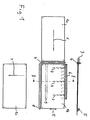
- Fig. 1 shows a schematic plan view of the transport table. Plates 1 can retract from the left side in an X direction lying horizontally in FIG. 1 and Extend in a Y direction lying vertically in FIG. 1 (downwards in FIG. 1). in the 1 is a schematic sectional view along a top right area X-cutting direction is shown, which shows that in front of the actual transport table 2, a roller conveyor 3 running from the left in the X direction is. About this roller transport path 3, plates, such as the one designated in Fig. 1 with 1a Plate, moved up to the transport table 2 and there directly from one X-roller unit 4 arranged in front of the transport table 2 is detected. The axes of rotation of the Rollers of the roller unit 4 lying vertically one above the other lie parallel to the Y direction.
- a plate 1 can then be increasingly delayed are fed to the transport table 2 until they are elastic at one in the X direction yielding stop 5 abuts.
- This stop 5 does not take large forces more on, rather the plates 1 are almost complete before contact with the stop 5 braked. It only serves as a security attack. It can also be used for Serve positioning on a Y fixed edge embodied by him.
- the X-stop 5 can be adjustable along the X direction, so that the Transport table 2 can be set to different formats of the plates 1.
- a plate abutting the stop 5 is designated 1b.
- the plate 1b has just left the X-roll mill 4.
- a cross slide 6 is arranged, the detailed structure will be explained in more detail with reference to FIG. 2.
- the cross slide 6 is over a driving range corresponding to lines denoted by 7 (with 7 Slots designated for holders of the cross slide 6, which are shown in FIG. 2 in more detail explained) can be moved in the Y direction, in this example approximately up to the center of the width of the plate 1b in the Y direction.
- the slider can the plate 1b a Y roller unit 8 arranged directly in front of its front edge in the Y direction feed that corresponds structurally to the already mentioned X-roller unit 4, wherein however, the axes are parallel to the X direction.
- the plate 1b is then from the Y-roll mechanism 8 detected and further accelerated in the Y direction. If the plate about half went through the Y-roll mechanism 8, it has the Leave the travel range of the cross slide 6, so that the extension in the following through the Y-roll mechanism 8 and - optionally - further transport devices in the Y direction can take place downstream of the Y-roll mechanism 8.
- Such Transport devices can be another roller conveyor, which is not in the figure is shown in detail.
- the transport table 2 thus serves as 90 ° -Winkelstation.
- the plate 1c shown in FIG. 1 has the Y-roll mechanism as an example 8 already left and continues on the Y transport track. she stays thereby on the reference edge predetermined by the X stop 5 along the Y direction aligned.
- the section line II-II drawn in Fig. 1 illustrates the perspective of the schematic Sectional view from Fig. 2. So there is the X direction perpendicular to Drawing plane and the Y direction horizontal in it (pointing to the right).
- the transport table 2 is an actual table surface 10 with recesses for the slide bar 9 and brackets of the cross slide 6.
- the Y-roll mechanism 8 is shown.
- the plate 1d is in the situation shown by the X roller assembly 4, not shown, is held and, moreover, slides on the upper one Sliding edge of the cross slide 6.
- the plastic is selected so that it has a low coefficient of friction with that used Has plate material and leaves no traces.
- the plate 1e is the plate running ahead and already in the lower-lying cross slide transport plane lowered so that it moves from the cross slide 6 in the Y direction, i.e. 2 to the right, from the area of the transport table 2 and is extended by the Y-roll mechanism 8.
- Fig. 2 clearly shows the significant Overlap between plates 1d and 1e.
- the slide bar 9 is shown, which is under a corresponding recess the actual table surface 10 is arranged and when the plate 1e in Y direction has moved beyond the slide bar 9, can be raised.
- thin lines show that it also supports the plate 1d, this that is, on the upper side of the slide bar 9, which is configured analogously to the cross slide 6 can slide.
- the lifting and lowering movement of the slide bar 9 takes place on the one hand via a guide on a pivotable about an axis 11 lever 12 and driven to the second by a pneumatic cylinder 13.
- the cross slide 6 is moved and driven by a linear guide 14 by a belt drive 15 with a motor drive 16.
- a linear guide 14 On the linear guide 14 supports 17 are attached, which extend horizontally in FIG Grip slots 7 in table surface 10 and hold cross slide 6.
Landscapes
- Engineering & Computer Science (AREA)
- Mechanical Engineering (AREA)
- Attitude Control For Articles On Conveyors (AREA)
Abstract
Description
- Fig. 1
- zeigt eine schematische Draufsicht auf einen erfindungsgemäßen Transporttisch.
- Fig. 2
- zeigt eine schematische Schnittansicht durch den Transporttisch aus Fig. 1.
Claims (13)
- Transporttisch (2) zum Umlenken transportierter Platten (1),
auf den Platten (1a, 1d, 1b) in einer X-Richtung eingefahren werden können
und der einen in einer Schiebertransportebene verfahrbaren Querschieber (6) aufweist, der dazu ausgelegt ist, die Platten (1e) auf dem Transporttisch (2) in einer quer zu der X-Richtung und in der Schiebertransportebene liegenden Y-Richtung zu beschleunigen,
so dass die Platten (1e, 1c) durch den Transporttisch (2) aus der X-Richtung in die Y-Richtung umgelenkt und in der Y-Richtung ausgefahren werden können,
dadurch gekennzeichnet, dass der Transporttisch (2) dazu ausgelegt ist, die Platten (1a, 1d) in der X-Richtung zunächst in einer Einfahrtransportebene einzufahren, die höher als die Schiebertransportebene und der Querschieber (6) angeordnet ist,
die Platten (1 b) dann in die Schiebertransportebene abzusenken
und dann in der Schiebertransportebene durch den Querschieber (6) zu beschleunigen,
und jeweils nachfolgende Platten (1d) in der Einfahrtransportebene noch während des Ausfahrens der vorderen Platten (1e) einzufahren, so dass sich in einer zu der X-Richtung und der Y-Richtung senkrechten Z-Richtung eine Überlappung aufeinanderfolgender Platten (1d, 1e) ergibt. - Transporttisch (2) nach Anspruch 1, bei dem der Querschieber (6) eine als Gleitkante für einfahrende Platten (1d) ausgestaltete Oberseite aufweist.
- Transporttisch (2) nach Anspruch 1 oder 2 mit einem vor einem durch den Querschieber (6) erfassten Fahrbereich angeordneten X-Rollenwerk (4) zum Verzögern der Platten (1) beim Einfahren.
- Transporttisch (2) nach Anspruch 1, 2 oder 3 mit einem vor einem durch den Querschieber (6) erfassten Fahrbereich angeordneten X-Rollenwerk (4) zum Halten der Platten (1) in der Y-Richtung, um einem unbeabsichtigten Verschieben der Platten (1) durch den Querschieber (6) entgegen zu wirken.
- Transporttisch (2) nach einem der vorstehenden Ansprüche mit einem hinter einen durch den Querschieber (6) erfassten Fahrbereich angeordneten Y-Rollenwerk (8) zur Unterstützung des Plattentransports beim Ausfahren.
- Transporttisch (2) nach einem der vorstehenden Ansprüche mit einem hinter einem durch den Querschieber (6) erfassten Fahrbereich angeordneten X-Anschlag (5) für einfahrende Platten (1).
- Transporttisch (2) nach Anspruch 6, bei dem der X-Anschlag (5) zur Anpassung an verschiedene Plattenformate in der X-Richtung einstellbar ist.
- Transporttisch (2) nach einem der vorstehenden Ansprüche, der so ausgelegt ist, dass die Platten (1b) jeweils in der X-Richtung ganz in einen durch den Querschieber (6) erfassten Fahrbereich einfahren, bevor der Querschieber (6) die Platten (1e) jeweils in der Y-Richtung beschleunigt.
- Transporttisch (2) nach einem der vorstehenden Ansprüche, bei dem der Querschieber (6) durch eine Linearführung (14) geführt und über einen Riemenantrieb (15, 16) angetrieben ist.
- Transporttisch (2) nach einem der vorstehenden Ansprüche mit einer in einer zu der X-Richtung und zu der Y-Richtung senkrechten Z-Richtung heb- und senkbaren Gleitleiste (9), die eine als Gleitkante ausgebildete Oberseite aufweist und mit ihrer Längsrichtung parallel zu der X-Richtung so angeordnet ist, dass sie beim Absenken eingefahrener Platten (1 b) ihrerseits abgesenkt ist, um in der Schiebertransportebene nicht zu stören, und andererseits beim Ausfahren von Platten (1) hinter diesen angehoben werden kann, um eine nachfolgende Platte über der vorderen Platte zu halten und damit eine gegenseitige Beschädigung in X-Richtung verlaufender Kanten der aufeinanderfolgenden Platten zu vermeiden.
- Transporttisch (2) nach Anspruch 10, bei dem die Gleitleiste (9) über eine Hebelführung (11, 12) geführt und über einen Pneumatikzylinder (13) angetrieben ist.
- Verfahren zum Umlenken transportierter Platten (1 ) auf einem Transporttisch (2) , bei dem die Platten (1a, 1b) in einer X-Richtung auf den Transporttisch (2) eingefahren werden,
mit einem in einer Schiebertransportebene verfahrbaren Querschieber (6) in einer zu der X-Richtung quer und in der Schiebertransportebene liegenden Y-Richtung beschleunigt werden,
so dass die Platten (1e, 1c) aus der X-Richtung in die Y-Richtung umgelenkt und in der Y-Richtung ausgefahren werden,
dadurch gekennzeichnet, dass die Platten (1a, 1d) in der X-Richtung zunächst in einer Einfahrtransportebene eingefahren werden, die höher als die Schiebertransportebene und der Querschieber (6) angeordnet ist,
dann in die Schiebertransportebene abgesenkt werden
und dann in der Schiebertransportebene durch den Querschieber (6) beschleunigt werden,
und jeweils nachfolgende Platten (1d) in der Einfahrtransportebene noch während des Ausfahrens der vorderen Platten (1e) eingefahren werden, so dass sich in einer zu der X-Richtung und der Y-Richtung senkrechten Z-Richtung eine Überlappung aufeinanderfolgender Platten (1d, 1e) ergibt. - Verfahren nach Anspruch 12 unter Verwendung eines Transporttisches (2) nach einem der Ansprüche 2 bis 11.
Priority Applications (2)
| Application Number | Priority Date | Filing Date | Title |
|---|---|---|---|
| DE50203899T DE50203899D1 (de) | 2002-09-17 | 2002-09-17 | Vorrichtung und Verfahren zum Umlenken transportierter Platten mit einem Querschieber |
| EP20020020808 EP1400470B1 (de) | 2002-09-17 | 2002-09-17 | Vorrichtung und Verfahren zum Umlenken transportierter Platten mit einem Querschieber |
Applications Claiming Priority (1)
| Application Number | Priority Date | Filing Date | Title |
|---|---|---|---|
| EP20020020808 EP1400470B1 (de) | 2002-09-17 | 2002-09-17 | Vorrichtung und Verfahren zum Umlenken transportierter Platten mit einem Querschieber |
Publications (2)
| Publication Number | Publication Date |
|---|---|
| EP1400470A1 true EP1400470A1 (de) | 2004-03-24 |
| EP1400470B1 EP1400470B1 (de) | 2005-08-10 |
Family
ID=31896863
Family Applications (1)
| Application Number | Title | Priority Date | Filing Date |
|---|---|---|---|
| EP20020020808 Expired - Lifetime EP1400470B1 (de) | 2002-09-17 | 2002-09-17 | Vorrichtung und Verfahren zum Umlenken transportierter Platten mit einem Querschieber |
Country Status (2)
| Country | Link |
|---|---|
| EP (1) | EP1400470B1 (de) |
| DE (1) | DE50203899D1 (de) |
Cited By (1)
| Publication number | Priority date | Publication date | Assignee | Title |
|---|---|---|---|---|
| CN117566409A (zh) * | 2023-11-23 | 2024-02-20 | 北新集团建材股份有限公司 | 一种触发式石膏板转向输送自动行进装置 |
Citations (2)
| Publication number | Priority date | Publication date | Assignee | Title |
|---|---|---|---|---|
| US3463295A (en) * | 1967-07-31 | 1969-08-26 | Potlatch Forests Inc | Apparatus for overlapping scarfed veneer sheets |
| DE29723395U1 (de) * | 1997-07-16 | 1998-08-20 | Podnar, Michael, 42327 Wuppertal | Vorrichtung zum Stapeln von stückigem Gut, insbesondere quaderförmigen Packungen |
-
2002
- 2002-09-17 DE DE50203899T patent/DE50203899D1/de not_active Expired - Lifetime
- 2002-09-17 EP EP20020020808 patent/EP1400470B1/de not_active Expired - Lifetime
Patent Citations (2)
| Publication number | Priority date | Publication date | Assignee | Title |
|---|---|---|---|---|
| US3463295A (en) * | 1967-07-31 | 1969-08-26 | Potlatch Forests Inc | Apparatus for overlapping scarfed veneer sheets |
| DE29723395U1 (de) * | 1997-07-16 | 1998-08-20 | Podnar, Michael, 42327 Wuppertal | Vorrichtung zum Stapeln von stückigem Gut, insbesondere quaderförmigen Packungen |
Cited By (1)
| Publication number | Priority date | Publication date | Assignee | Title |
|---|---|---|---|---|
| CN117566409A (zh) * | 2023-11-23 | 2024-02-20 | 北新集团建材股份有限公司 | 一种触发式石膏板转向输送自动行进装置 |
Also Published As
| Publication number | Publication date |
|---|---|
| DE50203899D1 (de) | 2005-09-15 |
| EP1400470B1 (de) | 2005-08-10 |
Similar Documents
| Publication | Publication Date | Title |
|---|---|---|
| DE68919977T2 (de) | Schachtelschneidevorrichtung und -verfahren. | |
| DE3111256C2 (de) | ||
| DE3303956C2 (de) | Vorrichtung zum Umreifen eines quaderförmigen Packgutes | |
| EP3563959A1 (de) | Sägevorrichtung | |
| EP3498637B1 (de) | Transportanordnung für holzfaserplatten und verfahren zum transportieren von holzfaserplatten | |
| EP4230369B1 (de) | Plattenaufteilanlage | |
| EP1883538B1 (de) | Haltevorrichtung für tintenstrahldrucker | |
| DE3716666A1 (de) | Plattenaufteilanlage mit einer laengssaege und einer quersaege | |
| EP0504442B1 (de) | Vorrichtung zum Zuführen von Werkstücken zu einer Bearbeitungsmaschine | |
| EP0270493B1 (de) | Winkelschere | |
| DE2312376C2 (de) | Aufteilsägemaschine | |
| DE102021125391B4 (de) | Entstapelungsvorrichtung und Holzbearbeitungsanlage mit einer derartigen Entstapelungsvorrichtung | |
| AT390026B (de) | Vorrichtung zum buntaufteilen von plattenfoermigen werkstuecken | |
| DE2106091C3 (de) | Vorrichtung zum verschachtelten, lageweisen Stapeln von profiliertem Walzgut | |
| DE3632018A1 (de) | Aufteilanlage fuer plattenfoermige werkstuecke | |
| DE2518359A1 (de) | Holzbearbeitungs-maschine | |
| EP2158070B1 (de) | Transportvorrichtung für eine keilverzinkungsanlage | |
| EP1400470B1 (de) | Vorrichtung und Verfahren zum Umlenken transportierter Platten mit einem Querschieber | |
| DE10047385C2 (de) | Verfahren und Vorrichtung zur Bearbeitung von fortlaufend bewegten Werkstücken | |
| EP3369663B1 (de) | Bundbildungseinrichtung für längliche werkstücke sowie verfahren zum bündeln von länglichen werkstücken | |
| EP0026755B1 (de) | Zubringervorrichtung für Blechbearbeitungsmaschinen | |
| EP4353432A1 (de) | Plattenaufteilanlage | |
| DE2828210A1 (de) | Vorrichtung zum vereinzeln stirnseitig keilgezinkter bretter aus einem paket und zum zusammenfuegen zu einem strang | |
| DE3827108C2 (de) | Abstapler | |
| DE19839923C2 (de) | Vorrichtung zur Abnahme von Folien von einem Folienstapel in einer Stapelstation und zur Ablage der abgenommenen Folien in einer Zusammenlegestation |
Legal Events
| Date | Code | Title | Description |
|---|---|---|---|
| PUAI | Public reference made under article 153(3) epc to a published international application that has entered the european phase |
Free format text: ORIGINAL CODE: 0009012 |
|
| 17P | Request for examination filed |
Effective date: 20030625 |
|
| AK | Designated contracting states |
Kind code of ref document: A1 Designated state(s): AT BE BG CH CY CZ DE DK EE ES FI FR GB GR IE IT LI LU MC NL PT SE SK TR |
|
| AX | Request for extension of the european patent |
Extension state: AL LT LV MK RO SI |
|
| RAP3 | Party data changed (applicant data changed or rights of an application transferred) |
Owner name: SHS SIEMPELKAMP HANDLING SYSTEME GMBH & CO |
|
| GRAP | Despatch of communication of intention to grant a patent |
Free format text: ORIGINAL CODE: EPIDOSNIGR1 |
|
| AKX | Designation fees paid |
Designated state(s): DE FI IT SE |
|
| GRAS | Grant fee paid |
Free format text: ORIGINAL CODE: EPIDOSNIGR3 |
|
| GRAA | (expected) grant |
Free format text: ORIGINAL CODE: 0009210 |
|
| AK | Designated contracting states |
Kind code of ref document: B1 Designated state(s): DE FI IT SE |
|
| REF | Corresponds to: |
Ref document number: 50203899 Country of ref document: DE Date of ref document: 20050915 Kind code of ref document: P |
|
| REG | Reference to a national code |
Ref country code: SE Ref legal event code: TRGR |
|
| RAP4 | Party data changed (patent owner data changed or rights of a patent transferred) |
Owner name: SHS SIEMPELKAMP HANDLING SYSTEME GMBH & CO |
|
| PLBE | No opposition filed within time limit |
Free format text: ORIGINAL CODE: 0009261 |
|
| STAA | Information on the status of an ep patent application or granted ep patent |
Free format text: STATUS: NO OPPOSITION FILED WITHIN TIME LIMIT |
|
| 26N | No opposition filed |
Effective date: 20060511 |
|
| REG | Reference to a national code |
Ref country code: DE Ref legal event code: R081 Ref document number: 50203899 Country of ref document: DE Owner name: SIEMPELKAMP MASCHINEN - UND ANLAGENBAU, DE Free format text: FORMER OWNER: SIEMPELKAMP HANDLING SYSTEME GMBH & CO, 82515 WOLFRATSHAUSEN, DE Effective date: 20110509 |
|
| PGFP | Annual fee paid to national office [announced via postgrant information from national office to epo] |
Ref country code: FI Payment date: 20130923 Year of fee payment: 12 Ref country code: SE Payment date: 20130925 Year of fee payment: 12 |
|
| PGFP | Annual fee paid to national office [announced via postgrant information from national office to epo] |
Ref country code: IT Payment date: 20130921 Year of fee payment: 12 |
|
| PGFP | Annual fee paid to national office [announced via postgrant information from national office to epo] |
Ref country code: DE Payment date: 20130930 Year of fee payment: 12 |
|
| REG | Reference to a national code |
Ref country code: DE Ref legal event code: R119 Ref document number: 50203899 Country of ref document: DE |
|
| PG25 | Lapsed in a contracting state [announced via postgrant information from national office to epo] |
Ref country code: FI Free format text: LAPSE BECAUSE OF NON-PAYMENT OF DUE FEES Effective date: 20140917 |
|
| REG | Reference to a national code |
Ref country code: SE Ref legal event code: EUG |
|
| PG25 | Lapsed in a contracting state [announced via postgrant information from national office to epo] |
Ref country code: SE Free format text: LAPSE BECAUSE OF NON-PAYMENT OF DUE FEES Effective date: 20140918 |
|
| REG | Reference to a national code |
Ref country code: DE Ref legal event code: R119 Ref document number: 50203899 Country of ref document: DE Effective date: 20150401 |
|
| PG25 | Lapsed in a contracting state [announced via postgrant information from national office to epo] |
Ref country code: DE Free format text: LAPSE BECAUSE OF NON-PAYMENT OF DUE FEES Effective date: 20150401 |
|
| PG25 | Lapsed in a contracting state [announced via postgrant information from national office to epo] |
Ref country code: IT Free format text: LAPSE BECAUSE OF NON-PAYMENT OF DUE FEES Effective date: 20140917 |