EP1398552B1 - Support pivotant pour un tuyau - Google Patents
Support pivotant pour un tuyau Download PDFInfo
- Publication number
- EP1398552B1 EP1398552B1 EP20030020628 EP03020628A EP1398552B1 EP 1398552 B1 EP1398552 B1 EP 1398552B1 EP 20030020628 EP20030020628 EP 20030020628 EP 03020628 A EP03020628 A EP 03020628A EP 1398552 B1 EP1398552 B1 EP 1398552B1
- Authority
- EP
- European Patent Office
- Prior art keywords
- receptacle
- holder according
- pipe
- axis
- yoke
- Prior art date
- Legal status (The legal status is an assumption and is not a legal conclusion. Google has not performed a legal analysis and makes no representation as to the accuracy of the status listed.)
- Expired - Lifetime
Links
- NJPPVKZQTLUDBO-UHFFFAOYSA-N novaluron Chemical compound C1=C(Cl)C(OC(F)(F)C(OC(F)(F)F)F)=CC=C1NC(=O)NC(=O)C1=C(F)C=CC=C1F NJPPVKZQTLUDBO-UHFFFAOYSA-N 0.000 claims description 3
- 230000000295 complement effect Effects 0.000 claims description 2
- 241000047428 Halter Species 0.000 description 4
- 244000089486 Phragmites australis subsp australis Species 0.000 description 3
- 238000006073 displacement reaction Methods 0.000 description 3
- 230000002093 peripheral effect Effects 0.000 description 3
- 239000002131 composite material Substances 0.000 description 1
- 238000002347 injection Methods 0.000 description 1
- 239000007924 injection Substances 0.000 description 1
- 238000011144 upstream manufacturing Methods 0.000 description 1
Images


Classifications
-
- F—MECHANICAL ENGINEERING; LIGHTING; HEATING; WEAPONS; BLASTING
- F16—ENGINEERING ELEMENTS AND UNITS; GENERAL MEASURES FOR PRODUCING AND MAINTAINING EFFECTIVE FUNCTIONING OF MACHINES OR INSTALLATIONS; THERMAL INSULATION IN GENERAL
- F16L—PIPES; JOINTS OR FITTINGS FOR PIPES; SUPPORTS FOR PIPES, CABLES OR PROTECTIVE TUBING; MEANS FOR THERMAL INSULATION IN GENERAL
- F16L3/00—Supports for pipes, cables or protective tubing, e.g. hangers, holders, clamps, cleats, clips, brackets
- F16L3/16—Supports for pipes, cables or protective tubing, e.g. hangers, holders, clamps, cleats, clips, brackets with special provision allowing movement of the pipe
Definitions
- the invention relates to a holder for the pivotable mounting of a tube, in particular a corrugated tube.
- the holder according to the invention is preferably used for holding a cable conduit designed as a corrugated pipe, which receives one or more power supply or control cable, to a robot such that the corrugated pipe can follow the pivotal movements of the robot arms or the like.
- a holder for a garden hose which allows two pivotable about mutually orthogonal axes holding parts a pivoting of the garden hose in the vertical and horizontal directions in the manner of a universal joint, but one of the pivot axes does not extend through the tube axis and the holder is locked self-locking in the respective pivot position.
- a holder for a burner tube of a gas turbine in which the burner tube is fixed at its end to the turbine housing and is also held at two axially spaced locations in a fork, on which the burner tube to a vertical rotatably or flexibly to the turbine housing is mounted such that the two forks form a parallelogram for the burner tube, which allows small movements or expansions of the burner tube in its longitudinal direction.
- the invention has for its object to provide a particularly simple and inexpensive to produce holders for pivotally mounting a tube, in particular corrugated tube, which allows the greatest possible freedom of movement of the tube for pivotal movements in all directions and especially for guiding cable conduits for robots or the like. suitable.
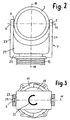
- a corrugated tube 1 is received in an annular receptacle 3, which is shown in the upper part of Fig. 1 in section, otherwise in side view.
- the annular receptacle 3 is pivotally mounted by means of bearing pin 5 in the legs of a fork 7, so that the receptacle 3 with the corrugated tube 1 in the direction of the double arrow 9 about a first axis 11 is pivotally, in Fig. 1 perpendicular to the plane and thus perpendicular to the axis 13 of the tube 1, this cutting, runs.
- the fork 7 is rotatably supported by a rotary base 15 in a bearing ring 17 about the axis 19, which is perpendicular to the first axis of rotation 11 and the tube axis 13 intersects.
- the bearing ring 17 is z. B. with screws (not shown) to a pad 20, z. B. a structural part of a robot attached.
- Fig. 2 shows a frontal view of the annular receptacle 3, which is mounted by means of their bearing pin 5 on the legs 23 of the fork 7 about the axis 11 pivotally.
- On the lower part 25 of the fork 7 of the rotary base 15 is fixed, which is received in the bearing ring 17 (Fig. 1) to support the fork 7 rotatably about the axis 19.
- a stiffening web 27 may be located between the legs 23 of the fork.
- Fig. 3 shows seen from above the receptacle 3, which is mounted by means of its lateral bearing pin 5 in the bearing openings 29 of the (shown here in section) ends of the legs 23 of the fork 7. Also visible in Fig. 3 is the (later described in detail) bearing ring 17 in which the rotary base 15 of the fork 7 is rotatably mounted so that the fork 7 together with the holder 3 in the sense of the double arrow 31 of FIG the axis 19 (Fig. 2) can be rotated.
- the freedom of movement for the rotation about the vertical axis 19 in FIG. 1 is 360 °.
- the freedom of movement about the transverse axis 11 depends on the distance of the tube 1 from the pad 19 and thus u. a. from the height of the fork 7 and z. B. 130 °.
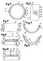
- the receptacle 3 is annular and composed of two semicircular jaws 3a, 3b.
- a single jaw 3a is shown in FIG. 6 as viewed in the direction of arrow A in FIG. 4 and in FIG. 7 in a view parallel to the axis.
- Each semicircular jaw 3a, 3b has two bearing surfaces 33 which lie in a common meridian plane and which adjoin one another to form the parting line 35 (FIG. 5) of the annular receptacle 3.
- Centering projections 37 and centering recesses 39 can be formed in the contact surfaces 33 in order to center the two jaws 3a, 3b exactly to one another.
- the semi-cylindrical bearing journals 5a, 5b are surrounded by over the peripheral surface of the jaws 3a, 3b raised shoulders 6a, 6b, which together form a bearing pin 5 surrounding annular abutment shoulder 6 (also shown in Fig. 2 in section), which abutment against the Inner surface of the legs 23 of the fork 7 is determined.
- a bearing pin 5 surrounding annular abutment shoulder 6 also shown in Fig. 2 in section
- the inner circumferential surface 41 of the receptacle 3 formed by the jaws 3a, 3b has, as can be seen from FIGS. 1 and 6, a smooth and preferably convexly curved shape.
- the corrugated tube 1 is slidably received in the receptacle 3 in the axial direction.
- an additional degree of freedom of the displacement in the direction of the tube axis 13 added.
- the receptacle 3 can be assembled from jaws of a different shape.
- An example is shown in FIGS. 8 and 9.
- the jaw 3c shown in FIGS. 8 and 9 differs from the jaw 3a according to FIG. 6 only in that a number of inwardly projecting ribs 43 are formed on the inner surface 41, which are inserted into the shaft grooves of the corrugated tube 1 (FIG 1) engage and thereby set the corrugated tube in the receptacle 3 immovable.
- FIG. 10 A further alternative embodiment of the jaws is shown in FIG. 10.
- the jaw 3d shown in FIG. 10 has on its inner peripheral surface an inwardly projecting step 45 as a stop for the end of a corrugated tube. Upstream of the stage 45 are one or two annular ribs 43 for engagement in the shaft grooves of the corrugated pipe.
- a composite of jaws 3d as shown in FIG. 10 receptacle 3 is used for such cases in which the corrugated tube should end in the holder and the corrugated tube end is to be secured in the receptacle 3 against withdrawal.
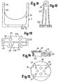
- the fork 7 shown in FIGS. 11 to 13 is an injection-molded part and has two legs 23 and a base 25. Between the legs 23, a stiffening web 27 extends in the legs 23, the bearing openings 29 are formed.
- the base 25 has, as can be seen in the plan view of Fig. 13, a rectangular widening 25a, in the area of openings 47 are formed for the passage of fastening screws.
- the rotary base 15 shown in Fig. 14 or 15 is an injection molded part having a circular plate 49 on the underside of which projects a circular cylindrical collar 51 having a number of protruding ribs 53 on its outer peripheral surface.
- the rotary base 15 has a shallow recess 55 whose shape is adapted to the contour of the base 25 of the fork 7 ( Figures 11 to 13) and of its extension 25a.
- the recess 55 thus forms a seat for the base 25 of the cable 7.
- screw holes 57 are formed in the plate 49, which are arranged corresponding to the openings 47 of the fork 7 and the fixing screws for fixing the fork 7 on the rotary base 15 record.
- the bearing ring 17 shown in Fig. 16 to 18 consists of two substantially semicircular jaws 17a, 17b, which are shown separately in Fig. 17 from each other and as shown in FIG. 18 can be fused together to form the complete bearing ring.
- Each Lagerringbakke 17 a, 17 b has at one end an elastic hook 61 which can engage behind a corresponding shoulder 63 of the other bearing ring jaw.
- Each bearing ring jaw 17a, 17b has z. B. two openings 65 for receiving mounting screws to the bearing ring 17 to a pad, z. B. the pad 20 in Fig. 1, to attach.
- Each of the bearing ring jaws 17a, 17b carries on its inner circumferential surface projecting ribs 67 which can engage between the ribs 53 of the bearing pedestal according to FIG. 14 in order to support the bearing cam 15 rotatably but immovably in the bearing ring 17 in the axial direction.
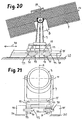
- the components of the holder according to FIGS. 20 and 21, namely the tube holder 3, the fork 7, the rotary base 15 and the bearing ring 17, are identical to those of the previously described embodiment and are designated by the same reference numerals.
- the difference of the embodiment of FIGS. 20 and 21 from the previous embodiment is that the bearing ring 17, in which the fork 7 is rotatably supported about the vertical axis 19 by means of the rotary base 15, is not fixed directly to the base 20 rigidly. Rather, four downwardly projecting axle 71 are fixed to the bearing ring 17, for example in its openings shown in Fig.
- Each guide roller 73 has a radially projecting flange 77, which engages in a guide groove 79 of the respective guide rail 75.
- This displaceability of the entire holder in the direction of displacement 70 can replace the displaceability of the corrugated tube 1 along the tube axis 13 in the tube receiving 3, so that the corrugated tube is spared.
Landscapes
- Engineering & Computer Science (AREA)
- General Engineering & Computer Science (AREA)
- Mechanical Engineering (AREA)
- Supports For Pipes And Cables (AREA)
Claims (11)
- Support pour un tube ou un dispositif similaire, avec un réceptacle (3) pour le tube (1) qui peut entourer le tube (1) sur une très grande partie de sa circonférence,
une fourche (7) sur laquelle le réceptacle (3) est logé de manière à pouvoir tourner autour d'un premier axe (11) et un coussinet de pivotement (15, 17) dans lequel la fourche (7) est logée de manière à pouvoir tourner autour d'un second axe (19),
le premier axe (11) étant perpendiculaire à l'axe (13) d'un tube (1) logé dans le réceptacle et le second axe (19) étant perpendiculaire au premier axe (11). - Support selon la revendication 1, caractérisé en ce que le réceptacle (3) est de forme annulaire et composé de deux mâchoires semi-circulaires (3a, 3b).
- Support selon la revendication 1 et 2, caractérisé en ce que le réceptacle (3) comporte deux tourillons (5) saillant vers l'extérieur, alignés l'un par rapport à l'autre, qui sont logés de manière rotative dans les ouvertures de logement correspondantes (29) de la fourche (7).
- Support selon la revendication 2 et 3, caractérisé en ce que chaque mâchoire (3a, 3b) comporte deux tourillons semi-circulaires (5a, 5b), les tourillons (5a, 5b) des deux mâchoires appliquées l'une à l'autre (3a, 3b) se complétant pour former des tourillons circulaires (5) qui sont logés ensemble dans les ouvertures de logement (29) de la fourche (7) et sont maintenus fixés l'un à l'autre par celles-ci.
- Support selon l'une quelconque des revendications 1 à 4, caractérisé en ce que le réceptacle (3) comporte, sur une circonférence interne (41), un profil lisse de telle sorte qu'un tube (1) logé, dans le réceptacle (3) soit guidé de manière à pouvoir être déplacé dans le sens longitudinal par rapport au réceptacle (3).
- Support selon l'une quelconque des revendications 1 à 4, caractérisé en ce que le réceptacle (3) comporte, sur une circonférence interne (41), au moins une saillie (43) qui est réalisée pour l'engrènement dans un creux de vague d'un tube ondulé (1) logé dans le réceptacle (3) de telle sorte que le tube ondulé (1) soit fixé dans le réceptacle (3) de manière à ne pas être déplaçable dans son sens longitudinal.
- Support selon la revendication 6, caractérisé en ce qu'au moins une saillie (45) est réalisée pour la fixation de l'extrémité d'un tube ondulé.
- Support selon l'une quelconque des revendications 1 à 7, caractérisé en ce que le palier rotatif (15, 17) comporte un socle rotatif (15) relié à la fourche (7) et un anneau de roulement (17) entourant le socle rotatif (15), des saillies (53, 67) et des rainures s'engrenant les unes dans les autres étant réalisées sur la circonférence du socle rotatif (15) et sur la circonférence interne de l'anneau de roulement (17).
- Support selon la revendication 8, caractérisé en ce que l'anneau de roulement (17) est composé de deux demi-cercles (17a, 17b) qui sont reliés l'un à l'autre par des liaisons à verrouillage (61, 63).
- Support selon la revendication 1, caractérisé en ce que le palier rotatif (15, 17) est guidé de manière à pouvoir être déplacé dans une glissière rectiligne (75).
- Support selon la revendication 10, caractérisé en ce que le palier rotatif (15, 17) comporte des galets de guidage (73) qui sont guidés sur des rails de guidage (75).
Applications Claiming Priority (2)
| Application Number | Priority Date | Filing Date | Title |
|---|---|---|---|
| DE20214103U DE20214103U1 (de) | 2002-09-12 | 2002-09-12 | Halter zur schwenkbaren Lagerung eines Rohres, insbesondere Wellrohres |
| DE20214103U | 2002-09-12 |
Publications (2)
| Publication Number | Publication Date |
|---|---|
| EP1398552A1 EP1398552A1 (fr) | 2004-03-17 |
| EP1398552B1 true EP1398552B1 (fr) | 2006-01-11 |
Family
ID=31724931
Family Applications (1)
| Application Number | Title | Priority Date | Filing Date |
|---|---|---|---|
| EP20030020628 Expired - Lifetime EP1398552B1 (fr) | 2002-09-12 | 2003-09-10 | Support pivotant pour un tuyau |
Country Status (2)
| Country | Link |
|---|---|
| EP (1) | EP1398552B1 (fr) |
| DE (2) | DE20214103U1 (fr) |
Families Citing this family (10)
| Publication number | Priority date | Publication date | Assignee | Title |
|---|---|---|---|---|
| DE102006025706B4 (de) * | 2006-06-01 | 2008-06-05 | Lisa Dräxlmaier GmbH | Wellrohrhalter |
| JP4261598B2 (ja) * | 2007-07-30 | 2009-04-30 | ファナック株式会社 | 産業用ロボットの線条体処理構造 |
| DE102010029737A1 (de) * | 2010-06-07 | 2011-12-08 | Kuka Roboter Gmbh | Haltevorrichtung für einen Leitungsstrang eines Industrieroboters |
| EP3124842B1 (fr) | 2014-03-28 | 2023-02-22 | Public Joint Stock Company "Transneft" | Support de conduit mobile et unité de support |
| WO2015147682A1 (fr) | 2014-03-28 | 2015-10-01 | Открытое акционерное общество "Акционерная компания по транспорту нефти "Транснефть" (ОАО "АК "Транснефть") | Support de conduit immobile |
| WO2015147685A1 (fr) | 2014-03-28 | 2015-10-01 | Открытое акционерное общество "Акционерная компания по транспорту нефти "Транснефть" (ОАО "АК "Транснефть") | Procédé d'installation de support immobile en position voulue |
| US9546745B2 (en) | 2015-04-13 | 2017-01-17 | Mueller International, Llc | Bi-directional roller assembly |
| CN106151686A (zh) * | 2016-08-26 | 2016-11-23 | 中国电力工程顾问集团中南电力设计院有限公司 | 一种热力管道用旋转限位支座及其旋转限位方法 |
| CN107676547B (zh) * | 2017-11-27 | 2019-08-09 | 常州轩豪机械有限公司 | 一种液压传动设备供油管固定装置 |
| CN113852329A (zh) * | 2021-07-27 | 2021-12-28 | 宁波住宅建设集团股份有限公司 | 一种光伏支架系统 |
Family Cites Families (10)
| Publication number | Priority date | Publication date | Assignee | Title |
|---|---|---|---|---|
| DE482629C (de) * | 1929-09-17 | Duerrwerke Akt Ges | Rollenlager mit einem oder mehreren isolierten Saetteln | |
| NL70468C (fr) * | 1945-02-20 | 1952-03-15 | ||
| US3415474A (en) * | 1966-10-21 | 1968-12-10 | Orlan C. Kindorf | Hanger for insulated pipe |
| US3390854A (en) * | 1966-10-28 | 1968-07-02 | Grinnell Corp | Movable bearing support |
| BE691082A (fr) * | 1966-12-12 | 1967-05-16 | ||
| DE2710601C2 (de) * | 1977-03-11 | 1984-07-26 | Wolfgang 7000 Stuttgart Kreikler | Rohrhalterung zur Befestigung von Rohren an Decken, Wänden o.dgl. |
| JPS5857581A (ja) * | 1981-10-02 | 1983-04-05 | 日揮株式会社 | 減衰機能を有する配管支持装置 |
| GB2258511B (en) * | 1991-07-31 | 1995-01-18 | Barry Richard Broome | A guide for an elongate flexible member |
| DE20107917U1 (de) * | 2001-05-10 | 2001-08-30 | Neuschwander, Martin, 78595 Hausen | Rohrbefestigung |
| DE10211212A1 (de) * | 2002-03-13 | 2003-09-25 | Andries Broekhuijsen | Roboterleitungsführungsvorrichtung |
-
2002
- 2002-09-12 DE DE20214103U patent/DE20214103U1/de not_active Expired - Lifetime
-
2003
- 2003-09-10 DE DE50302166T patent/DE50302166D1/de not_active Expired - Lifetime
- 2003-09-10 EP EP20030020628 patent/EP1398552B1/fr not_active Expired - Lifetime
Also Published As
| Publication number | Publication date |
|---|---|
| EP1398552A1 (fr) | 2004-03-17 |
| DE50302166D1 (de) | 2006-04-06 |
| DE20214103U1 (de) | 2004-02-12 |
Similar Documents
| Publication | Publication Date | Title |
|---|---|---|
| DE102008016572B4 (de) | Verbindungselement | |
| DE69612194T2 (de) | Selbstzentrierte stütze zur verwendung in rohren | |
| EP1398552B1 (fr) | Support pivotant pour un tuyau | |
| WO2015144613A1 (fr) | Bras de robot et kit de montage | |
| EP3310528B1 (fr) | Machine-outil pour l'usinage d'une pièce par enlèvement de copeaux | |
| DE19904702B4 (de) | Parallel-Kinematik-Maschine | |
| DE19712608A1 (de) | Abgasbehandlungsvorrichtung für Kraftfahrzeuge | |
| DE10321723A1 (de) | Schneidevorrichtung | |
| DE2914066C2 (de) | Rohrdrehgelenk | |
| DE69924764T2 (de) | Plandrehkopf | |
| EP4104977B1 (fr) | Robot avec fixations de connexion d'assemblage complémentaire | |
| DE3832244A1 (de) | Biegemaschine | |
| EP2392436A1 (fr) | Dispositif de retenue pour un faisceau de câbles d'un robot industriel | |
| WO2018010828A1 (fr) | Dispositif d'accouplement | |
| DE3405112A1 (de) | Lenkrolle fuer transportwagen, geraete, moebel u.dgl. | |
| EP0978353B1 (fr) | Meuleuse à carter de protection amovible | |
| DE3601895C1 (de) | Rohrverbindung | |
| DE3044142C2 (de) | Geräteträger zur dreiachsig verstellbaren Abstützung eines Gerätes | |
| DE19841812C1 (de) | Stumpfschweißmaschine für Kunststoffrohre | |
| EP1400740B1 (fr) | Dispositif de fixation d'un tuyau flexible | |
| DE102022115061B4 (de) | Zuführeinrichtung | |
| DE2620076A1 (de) | Halterungsvorrichtung fuer ein um sich selbst drehendes rad | |
| DE3045520C2 (de) | Zweiteilige Leitungsschelle | |
| DE202022002853U1 (de) | Zuführeinrichung | |
| WO2000022312A1 (fr) | Joint de cardan |
Legal Events
| Date | Code | Title | Description |
|---|---|---|---|
| PUAI | Public reference made under article 153(3) epc to a published international application that has entered the european phase |
Free format text: ORIGINAL CODE: 0009012 |
|
| AK | Designated contracting states |
Kind code of ref document: A1 Designated state(s): AT BE BG CH CY CZ DE DK EE ES FI FR GB GR HU IE IT LI LU MC NL PT RO SE SI SK TR |
|
| AX | Request for extension of the european patent |
Extension state: AL LT LV MK |
|
| 17P | Request for examination filed |
Effective date: 20040702 |
|
| 17Q | First examination report despatched |
Effective date: 20040929 |
|
| AKX | Designation fees paid |
Designated state(s): CH DE FR GB IT LI |
|
| GRAP | Despatch of communication of intention to grant a patent |
Free format text: ORIGINAL CODE: EPIDOSNIGR1 |
|
| GRAS | Grant fee paid |
Free format text: ORIGINAL CODE: EPIDOSNIGR3 |
|
| GRAA | (expected) grant |
Free format text: ORIGINAL CODE: 0009210 |
|
| AK | Designated contracting states |
Kind code of ref document: B1 Designated state(s): CH DE FR GB IT LI |
|
| REG | Reference to a national code |
Ref country code: CH Ref legal event code: EP |
|
| REG | Reference to a national code |
Ref country code: CH Ref legal event code: NV Representative=s name: TROESCH SCHEIDEGGER WERNER AG |
|
| REF | Corresponds to: |
Ref document number: 50302166 Country of ref document: DE Date of ref document: 20060406 Kind code of ref document: P |
|
| GBT | Gb: translation of ep patent filed (gb section 77(6)(a)/1977) |
Effective date: 20060410 |
|
| ET | Fr: translation filed | ||
| PLBE | No opposition filed within time limit |
Free format text: ORIGINAL CODE: 0009261 |
|
| STAA | Information on the status of an ep patent application or granted ep patent |
Free format text: STATUS: NO OPPOSITION FILED WITHIN TIME LIMIT |
|
| 26N | No opposition filed |
Effective date: 20061012 |
|
| REG | Reference to a national code |
Ref country code: FR Ref legal event code: PLFP Year of fee payment: 14 |
|
| REG | Reference to a national code |
Ref country code: FR Ref legal event code: PLFP Year of fee payment: 15 |
|
| REG | Reference to a national code |
Ref country code: FR Ref legal event code: PLFP Year of fee payment: 16 |
|
| PGFP | Annual fee paid to national office [announced via postgrant information from national office to epo] |
Ref country code: GB Payment date: 20220927 Year of fee payment: 20 Ref country code: DE Payment date: 20220926 Year of fee payment: 20 |
|
| PGFP | Annual fee paid to national office [announced via postgrant information from national office to epo] |
Ref country code: FR Payment date: 20220920 Year of fee payment: 20 |
|
| PGFP | Annual fee paid to national office [announced via postgrant information from national office to epo] |
Ref country code: IT Payment date: 20220930 Year of fee payment: 20 |
|
| PGFP | Annual fee paid to national office [announced via postgrant information from national office to epo] |
Ref country code: CH Payment date: 20220928 Year of fee payment: 20 |
|
| REG | Reference to a national code |
Ref country code: DE Ref legal event code: R071 Ref document number: 50302166 Country of ref document: DE |
|
| REG | Reference to a national code |
Ref country code: CH Ref legal event code: PL |
|
| REG | Reference to a national code |
Ref country code: GB Ref legal event code: PE20 Expiry date: 20230909 |
|
| PG25 | Lapsed in a contracting state [announced via postgrant information from national office to epo] |
Ref country code: GB Free format text: LAPSE BECAUSE OF EXPIRATION OF PROTECTION Effective date: 20230909 |