EP1398400A2 - Galvanisierungseinrichtung - Google Patents
Galvanisierungseinrichtung Download PDFInfo
- Publication number
- EP1398400A2 EP1398400A2 EP03019042A EP03019042A EP1398400A2 EP 1398400 A2 EP1398400 A2 EP 1398400A2 EP 03019042 A EP03019042 A EP 03019042A EP 03019042 A EP03019042 A EP 03019042A EP 1398400 A2 EP1398400 A2 EP 1398400A2
- Authority
- EP
- European Patent Office
- Prior art keywords
- bulkhead
- galvanizing device
- seal
- galvanizing
- cell
- Prior art date
- Legal status (The legal status is an assumption and is not a legal conclusion. Google has not performed a legal analysis and makes no representation as to the accuracy of the status listed.)
- Withdrawn
Links
Images


Classifications
-
- C—CHEMISTRY; METALLURGY
- C25—ELECTROLYTIC OR ELECTROPHORETIC PROCESSES; APPARATUS THEREFOR
- C25D—PROCESSES FOR THE ELECTROLYTIC OR ELECTROPHORETIC PRODUCTION OF COATINGS; ELECTROFORMING; APPARATUS THEREFOR
- C25D7/00—Electroplating characterised by the article coated
- C25D7/04—Tubes; Rings; Hollow bodies
-
- C—CHEMISTRY; METALLURGY
- C25—ELECTROLYTIC OR ELECTROPHORETIC PROCESSES; APPARATUS THEREFOR
- C25D—PROCESSES FOR THE ELECTROLYTIC OR ELECTROPHORETIC PRODUCTION OF COATINGS; ELECTROFORMING; APPARATUS THEREFOR
- C25D17/00—Constructional parts, or assemblies thereof, of cells for electrolytic coating
- C25D17/004—Sealing devices
-
- C—CHEMISTRY; METALLURGY
- C25—ELECTROLYTIC OR ELECTROPHORETIC PROCESSES; APPARATUS THEREFOR
- C25D—PROCESSES FOR THE ELECTROLYTIC OR ELECTROPHORETIC PRODUCTION OF COATINGS; ELECTROFORMING; APPARATUS THEREFOR
- C25D5/00—Electroplating characterised by the process; Pretreatment or after-treatment of workpieces
- C25D5/08—Electroplating with moving electrolyte e.g. jet electroplating
Definitions
- the invention relates to a galvanizing device at least one now cell, through which one to galvanizing workpiece, e.g. a brake line or the like, is passed through with an in Direction of transport arranged after the cell Contact zone and at least one of the cells from the Contact zone separating bulkhead, as well as a workpiece surrounding seal, which is between the bulkhead and the Jetzelle is arranged.
- one to galvanizing workpiece e.g. a brake line or the like
- Electroplating is used in electroplating Liquids (electrolytes) in which the workpieces immersed and in which they are covered with a metal be coated.
- Aqueous, acidic are used as electrolytes or alkaline solutions.
- the anodes are there mostly from the metal to be deposited.
- For galvanizing from e.g. A zinc electrolyte is used in steel. you dips the workpiece into the electrolyte and applies it the negative pole (cathode) of a DC voltage. additionally you dip a dissolving zinc anode (positive pole) into it Bath. They separate under the influence of the DC voltage split salt molecules depending on their charge.
- the positive zinc ions migrate to the negative pole, the Workpiece, and are deposited there.
- the invention is therefore based on the object Galvanizer to provide less Electrolyte is carried over and the service life of the Sealing is larger.
- the pre-bulkhead serves as a holder for a seal.
- a pre-seal is attached to the pre-bulkhead is attached or held by the bulkhead.
- a dynamic pressure is formed in the bulkhead which slows down the electrolyte current leaving the cell.
- the sealing of a wiper plate is preferred formed, which, however, since it is attached to the pre-bulkhead, is not subject to wear as it is the galvanized pipe not touched.
- the opening in the scraper plate can be chosen that only a small gap to the Workpiece remains so that almost all of the electrolyte is stripped. A carryover of electrolyte into the This reduces the contact zone to a minimum.
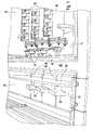
- FIG. 1 A total of three jet cells 10 can be seen in FIG. 1, which are arranged in an electroplating tub 12.
- the Now cells 10 are under high pressure from one Zinc electrolyte 14 flows through. It also runs through everyone Now cell 10 is a workpiece 16, namely a brake line 18.
- This brake line 18 is in a contact zone 20 in electrical contact with schematically shown cathodes 22, which are cooled by means of cooling water 24. Furthermore, in 1 shows a first bulkhead 26 and a second bulkhead 28 recognizable which the electroplating tub 12 from the contact zone 20 separate. Through the bulkheads a carryover of Zinc electrolyte 14 avoided in the contact zone 20.
- FIG. 2 which shows section II according to FIG shows enlarged view
- the output 30 is the Now cell 10 can be seen, on which a pre-bulkhead 32 is attached.
- the pre-bulkhead 32 generates a dynamic pressure for the zinc electrolyte 14 leaving the outlet 30, the thereby being slowed down.
- the pre-bulkhead 32 also serves as a holder for a total of 34 Seal, which is formed by a stripper plate 36.
- This scraper plate 36 has an opening that is slightly larger than the outer contour of the brake line 18, so that adhering to the outer circumference of the brake line 18 Zinc electrolyte 14 is stripped without contact.
- the Brake line 18 is thus free of zinc electrolyte 14. Da the brake line 18 electrolyte-free in the first and that second bulkhead 26 and 28 arrives, no zinc electrolyte 14 are dragged into the contact zone 20.
- FIG 3 is a perspective view Vorschott 32 shown as it is at the exit 30 of the Jetzelle 10 is used.
- the pre-bulkhead 32 has essentially a cubic bowl shape, with one side is missing.
- Two adjacent side walls 38 and 40 are provided with cutouts 42 and 44, the one for the Attaching the ballast 32 to the outlet 30 of the jet cell 10 serve, on the other hand for the passage of the brake line 18.
- the cutout 44 is open on the edge, so that Advance block 32 snapped onto output 30 without any problems can be.
- the cutout 42 is essentially slit-shaped, so that the bulkhead 32 over the Brake line 18 can be pushed over.
- the width of the Slit is slightly larger than the outside diameter the brake line 18, so that entrained electrolyte 14 is largely withheld.
- On the inside of the The side wall 38 has the stripping plate 36, which is held in position by the electrolyte level pressure.
Landscapes
- Chemical & Material Sciences (AREA)
- Engineering & Computer Science (AREA)
- Chemical Kinetics & Catalysis (AREA)
- Electrochemistry (AREA)
- Materials Engineering (AREA)
- Metallurgy (AREA)
- Organic Chemistry (AREA)
- Electroplating Methods And Accessories (AREA)
- Coating With Molten Metal (AREA)
- Braking Arrangements (AREA)
- Electrical Discharge Machining, Electrochemical Machining, And Combined Machining (AREA)
Abstract
Description
Dies hat den wesentlichen Vorteil, dass die Rohraußenseite unmittelbar am Ausgang der Jetzelle von anhaftendem Elektrolyt befreit wird und das von Elektrolyt befreite Rohr noch eine gewisse Wegstrecke zurücklegt, bis es durch das Schott in Richtung Kontaktzone hindurchtritt. Außerdem kann auf dieser Strecke evtl. noch auf der Rohraußenseite anhaftender Elektrolyt zusätzlich entfernt werden. Dies wäre nicht möglich, falls die Abdichtung, wie beim Stand der Technik, unmittelbar am Eingang des Schotts vorgesehen ist.
- Figur 1
- eine perspektivische Darstellung mehrer Jetzellen, einer Kontaktzone sowie eines dazwischen liegenden Schotts;
- Figur 2
- eine vergrößerte Wiedergabe eines Ausschnitts II gemäß Figur 1, den Ausgang einer Jetzelle mit Vorschott zeigend; und
- Figur 3
- eine perspektivische Ansicht eines Vorschotts.
Claims (10)
- Galvanisierungseinrichtung mit wenigstens einer Jetzelle (10), durch welche ein zu galvanisierendes Werkstück (16), z.B. eine Bremsleitung (18) oder dergleichen, hindurchgeführt wird, mit einer in Transportrichtung nach der Jetzelle (10) angeordneten Kontaktzone (20) und wenigstens einem die Jetzelle (10) von der Kontaktzone (20) trennenden Schott (26, 28), sowie einer das Werkstück (16) umgebenden Abdichtung (34), dadurch gekennzeichnet, dass die Abdichtung (34) am Ausgang (30) der Jetzelle (10) vorgesehen ist.
- Galvanisierungseinrichtung nach Anspruch 1, dadurch gekennzeichnet, dass der Ausgang (30) der Jetzelle (10) mit einem den Ausgang (30) umgebenden Vorschott (32) versehen ist.
- Galvanisierungseinrichtung nach Anspruch 2, dadurch gekennzeichnet, dass das Vorschott (32) als Halterung für die Abdichtung (34) dient.
- Galvanisierungseinrichtung nach Anspruch 2 oder 3, dadurch gekennzeichnet, dass im Vorschott (32) ein Staudruck gebildet wird, der den die Jetzelle (10) verlassenden Zinkelektrolytstrom (14) bremst.
- Galvanisierungseinrichtung nach einem der Ansprüche 2 bis 4, dadurch gekennzeichnet, dass die Abdichtung (34) von einer Abstreifplatte (36) gebildet wird.
- Galvanisierungseinrichtung nach Anspruch 5, dadurch gekennzeichnet, dass die Abdichtung (34) über das Vorschott (32) eine definierte Position bezüglich des Werkstücks (16) einnimmt.
- Galvanisierungseinrichtung nach einem der Ansprüche 2 bis 6, dadurch gekennzeichnet, dass das Vorschott (32) aus Kunststoff besteht.
- Galvanisierungseinrichtung nach einem der Ansprüche 2 bis 7, dadurch gekennzeichnet, dass das Vorschott (32) im wesentlichen eine kubische Napfform aufweist.
- Galvanisierungseinrichtung nach einem der vorhergehenden Ansprüche, dadurch gekennzeichnet, dass sie zum Galvanisieren von Bremsleitungen (18) ausgebildet ist.
- Galvanisierungseinrichtung nach einem der vorhergehenden Ansprüche, dadurch gekennzeichnet, dass sie eine high speed Galvanisierungseinrichtung ist.
Applications Claiming Priority (2)
| Application Number | Priority Date | Filing Date | Title |
|---|---|---|---|
| DE10242772A DE10242772B4 (de) | 2002-09-14 | 2002-09-14 | Galvanisierungseinrichtung |
| DE10242772 | 2002-09-14 |
Publications (2)
| Publication Number | Publication Date |
|---|---|
| EP1398400A2 true EP1398400A2 (de) | 2004-03-17 |
| EP1398400A3 EP1398400A3 (de) | 2006-10-04 |
Family
ID=31724780
Family Applications (1)
| Application Number | Title | Priority Date | Filing Date |
|---|---|---|---|
| EP03019042A Withdrawn EP1398400A3 (de) | 2002-09-14 | 2003-08-22 | Galvanisierungseinrichtung |
Country Status (3)
| Country | Link |
|---|---|
| US (1) | US7238264B2 (de) |
| EP (1) | EP1398400A3 (de) |
| DE (1) | DE10242772B4 (de) |
Family Cites Families (14)
| Publication number | Priority date | Publication date | Assignee | Title |
|---|---|---|---|---|
| GB761440A (en) * | 1952-07-24 | 1956-11-14 | Syncro Mach Co | Electroplating machine for wire strands |
| BE758436A (fr) * | 1969-06-06 | 1971-04-16 | Angelini S | Procede et appareillage pour le chromage continu en epaisseur de barres, fils et tubes a l'exterieur ou a l'interieur |
| US3852170A (en) * | 1970-11-13 | 1974-12-03 | Bes Brevetti Elettrogalvanici | Method and apparatus for carrying out continuous thick chrome plating of bar, wire and tube, both externally and internally |
| US3894924A (en) * | 1972-11-08 | 1975-07-15 | Raytheon Co | Apparatus for plating elongated bodies |
| FR2220600B2 (de) * | 1973-03-09 | 1976-09-10 | Mecano Bundy Gmbh | |
| JPS51137629A (en) * | 1975-05-23 | 1976-11-27 | Nippon Electro Plating | Highhspeed continuous plating method |
| DE2612730C2 (de) * | 1976-03-25 | 1983-05-26 | Electroplating Engineers of Japan, Ltd., Tokyo | Hochgeschwindigkeitsgalvanisierungseinrichtung für dünne Platten, Folien oder anderes flächiges Material |
| DE3023827C2 (de) * | 1980-06-25 | 1985-11-21 | Siemens AG, 1000 Berlin und 8000 München | Anlage zum galvanischen Abscheiden von Aluminium |
| IT1138370B (it) * | 1981-05-20 | 1986-09-17 | Brev Elettrogalvan Superfinitu | Metodo e apparecchiatura a doppia vasca,per la cromatura in continuo di barre e di pezzi di grosse dimensioni,con riciclo per la eliminazione dell'idrogeno |
| DE3438013A1 (de) * | 1984-10-17 | 1986-04-30 | Mannesmann AG, 4000 Düsseldorf | Metallisches rohr, das mit einem korrosionsschutz versehen ist, und verfahren zu dessen herstellung |
| IT1197479B (it) * | 1986-09-12 | 1988-11-30 | Angelini S | Cella per trattamento in continuo di deposizione elettrolitica su barre e simili |
| IT1251584B (it) * | 1991-10-02 | 1995-05-17 | Brev Elettrogalvan Superfinitu | Dispositivo intercambiabile di guida a tenuta per l'introduzione in continuo di elementi cilindrici in vasche di trattamento elettrolitico. |
| DE9400522U1 (de) * | 1994-01-13 | 1994-03-24 | Fulton-Rohr GmbH & Co. KG, 68766 Hockenheim | Rohrleitung für Systeme in Kraftfahrzeugen |
| IT1303889B1 (it) * | 1998-12-01 | 2001-03-01 | Giovanna Angelini | Procedimento ed apparecchiatura per la cromatura in continuo di barree relativa struttura di anodo |
-
2002
- 2002-09-14 DE DE10242772A patent/DE10242772B4/de not_active Expired - Fee Related
-
2003
- 2003-08-22 EP EP03019042A patent/EP1398400A3/de not_active Withdrawn
- 2003-09-12 US US10/661,703 patent/US7238264B2/en not_active Expired - Lifetime
Also Published As
| Publication number | Publication date |
|---|---|
| EP1398400A3 (de) | 2006-10-04 |
| US7238264B2 (en) | 2007-07-03 |
| US20040159542A1 (en) | 2004-08-19 |
| DE10242772A1 (de) | 2004-03-25 |
| DE10242772B4 (de) | 2005-06-09 |
Similar Documents
| Publication | Publication Date | Title |
|---|---|---|
| DE19717512C3 (de) | Vorrichtung zum Galvanisieren von Leiterplatten unter konstanten Bedingungen in Durchlaufanlagen | |
| DE102012206800B3 (de) | Verfahren und Vorrichtung zum elektrolytischen Abscheiden eines Abscheidemetalls auf einem Werkstück | |
| EP1007766A2 (de) | Vorrichtung und verfahren zum vergleichmässigen der dicke von metallschichten an elektrischen kontaktierstellen auf behandlungsgut | |
| DE1118565B (de) | Einrichtung zur Herstellung von Kupferblech durch galvanischen Niederschlag | |
| WO2003038158A2 (de) | Galvanisiereinrichtung und galvanisiersystem zum beschichten von bereits leitfähig ausgebildeten strukturen | |
| DE1496727B2 (de) | Verfahren zur elektrolytischen behandlung der innen und aussenflaeche von rohren | |
| DE2705158C2 (de) | Verfahren zum Teilgalvanisieren | |
| DE10242772B4 (de) | Galvanisierungseinrichtung | |
| EP0514796A1 (de) | Verfahren zum anodischen oder kathodischen Elektrolackieren von Band- oder Profilmaterial | |
| DE19633797B4 (de) | Vorrichtung zum Galvanisieren von elektronischen Leiterplatten oder dergleichen | |
| DE10234705A1 (de) | Galvanisiereinrichtung und Galvanisiersystem zum Beschichten von bereits leitfähig ausgebildeten Strukturen | |
| EP0369983A1 (de) | Verfahren und Vorrichtung zur elektrolytischen Herstellung einer Metallfolie | |
| DE102009013164A1 (de) | Verfahren und Vorrichtung zum elektrolytischen Behandeln von ausgedehntem Gut | |
| DE69501073T2 (de) | Zelle zur kontinuierlichen Elektrobeschichtung von Metalllegierungen | |
| EP0314053B1 (de) | Vorrichtung zur galvanischen Verstärkung einer Leiterspur auf einer Glasscheibe | |
| DE10215463C1 (de) | Durchlaufanlage und Verfahren zum elektrolytischen Metallisieren von Werkstück | |
| EP1753896A1 (de) | Verfahren und system zum selektiven beschichten oder ätzen von oberflächen | |
| EP0859071B1 (de) | Verfahren zum selektiven galvanischen Beschichten von elektrischen Kontaktelementen | |
| DE102004025827B3 (de) | Vorrichtung zum elektrischen Kontaktieren von ebenem Behandlungsgut in Durchlaufanlagen | |
| DE102006044673B3 (de) | Kontaktiereinheit für die galvanische Abscheidung, Galvanisiervorrichtung und Galvanisiersystem | |
| EP1168388A2 (de) | Verfahren zur Herstellung von Elektroden sowie damit hergestellte Elektroden | |
| DE2844708C2 (de) | Verfahren zur kontinuierlichen Galvanisierung eines Bandes aus porösem, nichtleitendem Material | |
| DE1496727C (de) | Verfahren zur elektrolytischen Behandlung der Innen- und Außenfläche von Rohren | |
| EP1201791A2 (de) | Anodenzelle zur kathodischen Elektro-Tauchlackierung von Werkstücken | |
| AT164823B (de) | Universalanlage zur Herstellung elektroplattierter Bänder, Bleche, Drähte u. dgl. Walzprodukte |
Legal Events
| Date | Code | Title | Description |
|---|---|---|---|
| PUAI | Public reference made under article 153(3) epc to a published international application that has entered the european phase |
Free format text: ORIGINAL CODE: 0009012 |
|
| AK | Designated contracting states |
Kind code of ref document: A2 Designated state(s): AT BE BG CH CY CZ DE DK EE ES FI FR GB GR HU IE IT LI LU MC NL PT RO SE SI SK TR |
|
| AX | Request for extension of the european patent |
Extension state: AL LT LV MK |
|
| PUAL | Search report despatched |
Free format text: ORIGINAL CODE: 0009013 |
|
| AK | Designated contracting states |
Kind code of ref document: A3 Designated state(s): AT BE BG CH CY CZ DE DK EE ES FI FR GB GR HU IE IT LI LU MC NL PT RO SE SI SK TR |
|
| AX | Request for extension of the european patent |
Extension state: AL LT LV MK |
|
| RIC1 | Information provided on ipc code assigned before grant |
Ipc: C25D 7/04 20060101ALI20060830BHEP Ipc: C25D 17/00 20060101AFI20031216BHEP |
|
| RIN1 | Information on inventor provided before grant (corrected) |
Inventor name: KULZER, PETER |
|
| AKX | Designation fees paid | ||
| STAA | Information on the status of an ep patent application or granted ep patent |
Free format text: STATUS: THE APPLICATION IS DEEMED TO BE WITHDRAWN |
|
| 18D | Application deemed to be withdrawn |
Effective date: 20070405 |
|
| REG | Reference to a national code |
Ref country code: DE Ref legal event code: 8566 |