EP1398258A2 - Klappbarer Rahmen für ein von physischer Kraft und/oder Motor angetriebenes Dreirad - Google Patents
Klappbarer Rahmen für ein von physischer Kraft und/oder Motor angetriebenes Dreirad Download PDFInfo
- Publication number
- EP1398258A2 EP1398258A2 EP03020328A EP03020328A EP1398258A2 EP 1398258 A2 EP1398258 A2 EP 1398258A2 EP 03020328 A EP03020328 A EP 03020328A EP 03020328 A EP03020328 A EP 03020328A EP 1398258 A2 EP1398258 A2 EP 1398258A2
- Authority
- EP
- European Patent Office
- Prior art keywords
- frame
- hinge
- configuration
- subframe
- tricycle
- Prior art date
- Legal status (The legal status is an assumption and is not a legal conclusion. Google has not performed a legal analysis and makes no representation as to the accuracy of the status listed.)
- Granted
Links
Images


Classifications
-
- B—PERFORMING OPERATIONS; TRANSPORTING
- B62—LAND VEHICLES FOR TRAVELLING OTHERWISE THAN ON RAILS
- B62K—CYCLES; CYCLE FRAMES; CYCLE STEERING DEVICES; RIDER-OPERATED TERMINAL CONTROLS SPECIALLY ADAPTED FOR CYCLES; CYCLE AXLE SUSPENSIONS; CYCLE SIDE-CARS, FORECARS, OR THE LIKE
- B62K5/00—Cycles with handlebars, equipped with three or more main road wheels
- B62K5/02—Tricycles
- B62K5/027—Motorcycles with three wheels
-
- B—PERFORMING OPERATIONS; TRANSPORTING
- B62—LAND VEHICLES FOR TRAVELLING OTHERWISE THAN ON RAILS
- B62K—CYCLES; CYCLE FRAMES; CYCLE STEERING DEVICES; RIDER-OPERATED TERMINAL CONTROLS SPECIALLY ADAPTED FOR CYCLES; CYCLE AXLE SUSPENSIONS; CYCLE SIDE-CARS, FORECARS, OR THE LIKE
- B62K15/00—Collapsible or foldable cycles
- B62K15/006—Collapsible or foldable cycles the frame being foldable
- B62K15/008—Collapsible or foldable cycles the frame being foldable foldable about 2 or more axes
Definitions
- the present invention relates to a foldable frame for a three-wheeled vehicle or so-called "tricycle” powered by physical force or a motor.
- the foldable frame is designed to permit a considerable reduction in size for easy stowage in the luggage compartment of a car, camper, aeroplane, etc.
- the present invention also relates to a tricycle comprising such a frame.
- Foldable tricycle frames are known which are folded and unfolded by hand, at times not without a certain amount of difficulty.
- Italian Patent IT-981 018 describes a foldable two-wheel vehicle frame comprising at least a first subframe in the form of an articulated quadrilateral and connected by means of at least one lever to a saddle fitted to a second subframe also in the form of an articulated quadrilateral.
- the first subframe is deformed so that the rear wheel of the vehicle moves towards the front wheel, thus reducing the length of the vehicle.
- Italian Patent IT-1 262 538 describes the front subframe of a vehicle with two or more wheels, in which the handlebar and the front wheel are connected by a mechanism, so that, once the handlebar is detached from a fastening hook, downward rotation of the handlebar about a hinge shifts a connecting rod, which in turn rotates the front fork about another hinge, thus simultaneously lowering the handlebar and moving the front wheel back to reduce the length and height of the vehicle.
- the present invention relates to a foldable frame for a three-wheeled vehicle (tricycle) powered by physical force or a motor, which incorporates a number of mechanisms for simultaneously reducing the size of the various subframes defining the foldable frame.
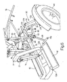
- Number 1000 in the accompanying drawings indicates a tricycle comprising a frame 100 in accordance with the present invention.
- Frame 100 in turn comprises a central subframe 10 forming the main subframe on which the other subframes and component elements of frame 100 are mounted.
- frame 100 also comprises a subframe 20 supporting a seat S; and two rear subframes 30, which are specular with respect to the longitudinal plane (a) of symmetry of frame 100, and each of which is fitted on the end with one of the two rear wheels W1 ( Figures 2, 5-9, 12).
- Frame 100 also comprises a subframe 40 by which to fold the backrest of seat S; and a front assembly 50 relative to the front fork, the direction wheel, and the handlebar of tricycle 1000 (see below).
- Tricycle 1000 may also comprise:
- subframes 10, 20, 30, 40 are all based on the known "articulated quadrilateral" principle.
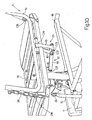
- Central subframe 10 in fact, is substantially defined by four members 11, 13, 14, 15 arranged in the form of an articulated quadrilateral.
- a front portion 11a of member 11 substantially supports a steering tube, which acts as a hinge for the front fork/handlebar assembly (see below); an intermediate portion 11b of member 11 supports two footrests 12 shown in Figure 1; and a top portion 11c of member 11 supports subframes 20 and 40.
- Member 13 opposite member 11, is fitted at the rear with two lateral subframes 30, each supporting a lateral wheel W1 ( Figures 1 and 2), and which, as stated, are specular with respect to the longitudinal plane (a) of symmetry of frame 100.
- Member 14 of central subframe 10 is hinged at one end by a hinge C1 to an intermediate point of member 11 (portion 11c), and at the other end by a hinge C2 to the front portion of member 13.
- Member 15 is hinged at one end by a hinge C3 to a point at the rear of member 11 (portion 11c), and at an intermediate point by a hinge C4 to an intermediate point of member 13.
- central subframe 10 can be converted from the unfolded configuration ( Figures 1, 5) corresponding to the running configuration of tricycle 1000, to a folded configuration ( Figure 7) corresponding to the minimum-size configuration of tricycle 1000.
- Devices can also be provided to lock frame 100 in each of the two limit configurations.
- a member 16, integral with member 15, serves as a luggage rack when tricycle 1000 is in the running configuration ( Figures 1, 5), and moves down within the rear outline of tricycle 1000 when frame 100 is folded into the minimum-size configuration (Figure 7).
- the force required to fold or unfold frame 100 may be transmitted by means of member 16.
- Subframe 20 substantially comprises the following four members arranged in the form of an articulated quadrilateral:
- subframe 20 can be converted from the unfolded configuration ( Figures 1, 5) corresponding to the running configuration of the tricycle, to a collapsed configuration on top of central subframe 10 and corresponding to the minimum-size configuration of tricycle 1000 ( Figures 7, 12).
- Central subframe 10 is connected to subframe 20 by two connecting rods 70 (only one shown in Figure 1) specular with respect to the longitudinal plane (a) of symmetry of frame 100.
- each connecting rod 70 is hinged by a hinge C9 to a projection of member 23 of subframe 20, and at the opposite end by a hinge C10 to a projection of member 14 of central subframe 10.
- the rear end of member 13 of central subframe 10 is fitted with two lateral subframes 30 specular with respect to the longitudinal plane (a) of symmetry of tricycle 1000.
- each of the two lateral subframes 30 substantially comprises the following four members, also arranged in the form of an articulated quadrilateral:
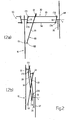
- each of the two lateral subframes 30 can be converted from the fully unfolded configuration ( Figures 1, 2a, 5) with respect to the longitudinal plane (a) of symmetry of tricycle 1000, to a withdrawn configuration adjacent to plane (a) ( Figures 2b and 7).
- members 33 and 34 are substantially perpendicular to the longitudinal plane (a) of symmetry of tricycle 1000, and wheel W1 is in the running configuration.
- Each lateral subframe 30 is connected to central subframe 10 by a mechanism 80 ( Figure 2a) comprising a connecting rod 81, which is connected at one end to a projection of member 33 by an articulated joint G1, and at the other end by an articulated joint G2 (see also Figure 1) to an extension 15a of member 15 of central subframe 10.
- lateral subframes 30 also assume the minimum-size configuration, with members 33, 34 and wheels W1 substantially adjacent to central subframe 10 ( Figure 2b) .
- a mechanism 90 which comprises a member 91 hinged by a hinge C15 to a projection of member 13, and by a hinge C16 to one end of a connecting rod 17, the other end of which is hinged by a hinge C17 to the end of an extension of member 15 of central subframe 10.
- a substantially rectangular seat portion 18 of seat S is fitted integrally to member 22 of subframe 22 and hinged at the rear by a hinge C18 to a backrest 19 of seat S.
- a mechanism 25 is provided to rotate backrest 19 about hinge C18 into a minimum-size configuration lying flat on seat portion 18 ( Figure 12). Conversely, when tricycle 1000 is unfolded into the running configuration, backrest 19 rotates into the erect position ( Figures 1, 3, 10).
- Backrest 19 of seat S is folded using folding mechanism 25, which comprises a subframe 40, in turn comprising the following four members arranged in the form of an articulated quadrilateral:
- Member 41 of subframe 40 is integral with member 24 of subframe 20.
- Mechanism 25 also comprises a connecting rod 26 hinged at one end by a hinge C23 to a projection of member 42, and at the other end by a hinge C24 to a projection of backrest 19 of seat S.
- each deformation of subframe 20 corresponds to a deformation of subframe 40 of folding mechanism 25 and displacement of connecting rod 26, which rotates backrest 19 about hinge C18 onto seat portion 18, as shown in detail in Figure 12.
- subframe 20 therefore corresponds at all times to the configuration of mechanism 25 and backrest 19, so that, when subframe 20 lies flat on member 11 of central subframe 10 in the minimum-size configuration of the tricycle, backrest 19 also lies flat on seat portion 18 in the minimum-size configuration. Conversely, when subframe 20 is unfolded upwards into the running configuration of tricycle 1000, so that seat S also assumes the as-used configuration, backrest 19 moves into a substantially erect as-used position.
- two lateral supporting members 27 are provided to increase the width of seat S in the as-used configuration, but which fold into a minimum-size configuration when tricycle 1000 is also folded into the minimum-size configuration.
- Each of the two lateral members 27 is substantially rectangular, and is hinged to one side of seat portion 18 by a hinge C25 having a substantially horizontal axis of rotation parallel to the longitudinal plane (a) of symmetry of seat S.
- portion 11b of member 11 of central subframe 10 is fitted at the bottom with two substantially rectangular footrests 12 ( Figures 1, 5, 6, 9) arranged specularly with respect to the longitudinal plane (a) of symmetry of frame 100.
- Each footrest 12 is hinged to portion 11b by a hinge C26 having a substantially horizontal axis of rotation parallel to the longitudinal plane (a) of symmetry of tricycle 1000.
- footrests 12 When tricycle 1000 is folded into the minimum-size configuration, footrests 12 must also be set to a minimum-size configuration, which is done by rotating footrests 12 about hinges C26 from the horizontal as-used position to a substantially vertical position of maximum compactness with respect to plane (a).
- the above rotation may be performed automatically when frame 100 is folded into the minimum-size configuration, as stated, by appropriately deforming interconnected subframes 10, 20, 30 and 40.
- member 32 of each lateral subframe 30 comprises a projection 35 integral with member 32 and so located that, when lateral subframe 30 is deformed from the extended running configuration to the minimum-size configuration, projection 35 slides along an inclined surface 36 ( Figure 9) formed on footrest 12, so that footrest 12 rotates about hinge C26 from a substantially horizontal as-used position to a substantially vertical minimum-size position. Conversely, when lateral subframe 30 is extended from the minimum-size configuration to the running configuration of the tricycle, projection 35 releases footrest 12, which returns, by force of gravity, to the horizontal as-used position, in which it is arrested by appropriate locking devices (not shown in Figure 1) formed on portion 11b of member 11 of central subframe 10.
- central subframe 10 may be equipped with a linear actuator 60 powered by an electric d.c. motor in turn powered by batteries (not shown) housed, for example, beneath luggage rack member 16.
- Actuator 60 is hinged at one end by a hinge C27 to a projection of portion 11c of member 11, and at the other end by a hinge C28 to a projection of member 15, so that each extension of linear actuator 60 corresponds to one, and only one, configuration of central subframe 10. More specifically, in the extended configuration, linear actuator 60 braces central subframe 10 in the extended configuration corresponding to the running configuration of tricycle 1000, whereas, in the withdrawn configuration, linear actuator 60 braces central subframe 10 in the deformed configuration corresponding to the minimum-size configuration of tricycle 1000.
- the front steering assembly 50 of frame 100 substantially comprises a front fork 51, a front direction wheel W2, and a handlebar 52.
- the component members of front steering assembly 50 are assembled as follows:
- Hinges C30, C31 and C32 are so located that, when handlebar 52 is in the raised running position, fork 51 is also forced into the running position; whereas, when handlebar 52 is folded down into the minimum-size position, front fork 51 is folded rearwards (in direction D) into the minimum-size configuration, in which wheel W2 is inserted between the two arms defining each of portions 11a, 11b of member 11, in the position shown by the dash line in Figure 1 (wheel W2'), thus greatly reducing the length and height of frame 100.
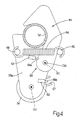
- a hook 61 is hinged to a portion 55a of member 55 by a hinge C33 having an axis (c) substantially parallel to the axis of rotation (b) of sleeve 53.
- Hook 61 rotates about axis (c) along an arc of rotation bounded at one end by a first stop member 62 integral with portion 55a of member 55, and at the other end by a second stop member 63 also integral with portion 55a.
- a spring 64 is hooked at one end to a projection 65 of hook 61, and at the other end to a projection 66 of portion 55a of member 55, so that hook 61 is forced to stably assume only the above two limit configurations.
- hook 61 When resting against first stop member 62 (hereinafter referred to as the "closed” position of hook 61) as shown in Figure 4, hook 61 prevents handlebar 52 from rotating about hinge C30 ( Figure 1), and locks it in the running position; whereas, when hook 61 rests against second stop member 63 (hereinafter referred to as the "open” position of hook 61), handlebar 52 is allowed to rotate about hinge C30.
- projection 65 (which extends on both sides with respect to the thickness of hook 61) fits inside a seat 67 integral with steering tube 54 integral with member 11 of central subframe 10.
- C-shaped member 55 is thus prevented from rotating about axis (b) of sleeve 53, by hook 61 connecting hinge C33 on member 55 to seat 67 integral with steering tube 54.
- handlebar 52 when hook 61 is open, handlebar 52 can be folded frontwards about hinge C30, and is prevented from rotating about axis (b) by member 55, which supports handlebar 52, being connected as described above to steering tube 54 integral with member 11 of central subframe 10.
- the angular position of seat 67 determines the angular position in which C-shaped member 55 is locked with respect to steering tube 54. More specifically, seat 67 is so located that member 55 is locked in a position in which the axis of hinge C29, integral with member 55, is perpendicular to the longitudinal plane (a) of symmetry of tricycle 1000. In this configuration, when handlebar 52 is lowered from the running to the minimum-size position, front fork 51 rotates about hinge C29, so that the plane of symmetry of wheel W2 is substantially coincident with the longitudinal plane (a) of symmetry of the tricycle.
- Foldable tricycle 1000 may be driven by an electric d.c. motor M, which may be housed, for example, in the hub of front wheel W2 ( Figure 1), and which is powered by batteries (not shown) located, for example, beneath luggage rack member 16.
- an electric d.c. motor M which may be housed, for example, in the hub of front wheel W2 ( Figure 1), and which is powered by batteries (not shown) located, for example, beneath luggage rack member 16.
- Tricycle 1000 is also equipped with an electric system (not shown) for controlling motor M and linear actuator 60 to perform the functions described previously.
- a safety device 68 prevents operation of actuator 60 to fold frame 100 when hook 61 is closed, and prevents operation of motor M when hook 61 is open.
- Safety device 68 substantially comprises a switch 69a fixed to projection 62 and connected to the electric circuit powering actuator 60. When closed, hook 61 presses against switch 69a to cut off the electric circuit to, and so prevent operation of, actuator 60.
- hook 61 presses against a switch 69b to cut off the electric circuit to, and so prevent operation of, motor M.
Landscapes
- Engineering & Computer Science (AREA)
- Mechanical Engineering (AREA)
- Automatic Cycles, And Cycles In General (AREA)
- Motorcycle And Bicycle Frame (AREA)
Applications Claiming Priority (2)
| Application Number | Priority Date | Filing Date | Title |
|---|---|---|---|
| IT000572A ITBO20020572A1 (it) | 2002-09-10 | 2002-09-10 | Telaio per triciclo pieghevole mosso a forza muscolare |
| ITBO20020572 | 2002-09-10 |
Publications (3)
| Publication Number | Publication Date |
|---|---|
| EP1398258A2 true EP1398258A2 (de) | 2004-03-17 |
| EP1398258A3 EP1398258A3 (de) | 2004-12-15 |
| EP1398258B1 EP1398258B1 (de) | 2009-11-11 |
Family
ID=31726538
Family Applications (1)
| Application Number | Title | Priority Date | Filing Date |
|---|---|---|---|
| EP03020328A Expired - Fee Related EP1398258B1 (de) | 2002-09-10 | 2003-09-09 | Klappbarer Rahmen für ein von physischer Kraft und/oder Motor angetriebenes Dreirad |
Country Status (4)
| Country | Link |
|---|---|
| US (1) | US7059621B2 (de) |
| EP (1) | EP1398258B1 (de) |
| DE (1) | DE60329957D1 (de) |
| IT (1) | ITBO20020572A1 (de) |
Cited By (7)
| Publication number | Priority date | Publication date | Assignee | Title |
|---|---|---|---|---|
| ITCT20100015A1 (it) * | 2010-10-01 | 2012-04-02 | Blasi Ind Srl Di | Veicolo pieghevole a tre o quattro ruote |
| EP2623407A1 (de) * | 2012-02-06 | 2013-08-07 | DI Blasi Industriale S.r.l. | Klappbares Fahrzeug |
| WO2013071907A3 (de) * | 2011-11-09 | 2014-02-13 | Hoerdum Martin | Faltrad |
| ITUB20154677A1 (it) * | 2015-09-24 | 2015-12-24 | Corrado Zaghini | triciclo elettrico multifunzione |
| CN105905216A (zh) * | 2015-02-25 | 2016-08-31 | 通用汽车环球科技运作有限责任公司 | 带有马达辅助折叠装置的自行车 |
| CN109278916A (zh) * | 2018-10-15 | 2019-01-29 | 王建民 | 拉杆箱式快速折叠微型电动车 |
| WO2020121100A1 (fr) * | 2018-12-14 | 2020-06-18 | Compagnie Générale Des Établissements Michelin | Vehicule a roue avant escamotable |
Families Citing this family (12)
| Publication number | Priority date | Publication date | Assignee | Title |
|---|---|---|---|---|
| US8181981B2 (en) * | 2008-02-26 | 2012-05-22 | Stenberg Eric E | Variable geometry cycle frame |
| CN101549724B (zh) * | 2009-05-20 | 2011-07-27 | 韩子超 | 全折叠人力、电动两用三轮车 |
| US8226104B2 (en) * | 2009-09-14 | 2012-07-24 | Konstantin Kulikov | Energy efficient tricycle |
| US8342555B2 (en) | 2010-04-13 | 2013-01-01 | Alan Roy Ball | Collapsible recumbent tricycle |
| US8523213B2 (en) | 2011-08-19 | 2013-09-03 | Thomas Raphael | Orthopedic mobility device |
| US20130062846A1 (en) * | 2011-09-09 | 2013-03-14 | Sunpex Technology Co., Ltd. | Collapsible frame structure of scooter |
| US10011316B2 (en) * | 2012-06-04 | 2018-07-03 | Smart Trike Mnf Pte Ltd. | Vehicle with foldable double-wheel assembly |
| US8714292B1 (en) * | 2012-09-19 | 2014-05-06 | Keith K. Wong | Motorized wheeled chair assembly |
| NL2012245C2 (en) | 2014-02-12 | 2015-08-17 | Royalty Bugaboo Gmbh | A foldable vehicle. |
| KR102398870B1 (ko) * | 2017-07-04 | 2022-05-17 | 현대자동차주식회사 | 주행 모드 변경이 가능한 소형 모빌리티 |
| IT201800009994A1 (it) * | 2018-10-31 | 2020-05-01 | Hydra Consulting Srl | Veicolo pieghevole per la mobilita' urbana |
| WO2020188345A1 (en) * | 2019-03-18 | 2020-09-24 | Motion Concepts L.P. | Suspension system for power wheelchair stander |
Citations (4)
| Publication number | Priority date | Publication date | Assignee | Title |
|---|---|---|---|---|
| US3887218A (en) * | 1973-02-28 | 1975-06-03 | Blasi Rosario Di | Collapsible vehicle |
| EP0648667A1 (de) * | 1993-10-14 | 1995-04-19 | DI BLASI S.r.l. | Zusammenklappbarer Rahmen für Zweirad- und Dreiradfahrzeug |
| EP1053168A1 (de) * | 1998-02-02 | 2000-11-22 | Alessandro Belli | Zweirad mit zusammenklappbarem rahmen mit betätigungskontrolle und übertragungsvorrichtung |
| EP1086888A2 (de) * | 1999-09-22 | 2001-03-28 | Carmelo Di Blasi | Klapprahmen für pedal- und/oder motorgetriebenes Dreirad |
Family Cites Families (7)
| Publication number | Priority date | Publication date | Assignee | Title |
|---|---|---|---|---|
| US1274045A (en) * | 1918-03-18 | 1918-07-30 | John Hudry | Combined velocipede, go-cart, and sled. |
| US5145196A (en) * | 1991-04-02 | 1992-09-08 | Langkamp Dennis J | Collapsible tricycle |
| JP3311163B2 (ja) * | 1994-09-21 | 2002-08-05 | アップリカ▲葛▼西株式会社 | 乳母車およびその座席のための座板の製造方法 |
| US5855387A (en) * | 1997-05-01 | 1999-01-05 | Caribbean Billing International, Ltd. | Wheel chair with independent suspension |
| US6325406B1 (en) * | 1999-10-08 | 2001-12-04 | American Recreation Products, Inc. | Collapsible stroller |
| ITVR20010022A1 (it) * | 2001-02-20 | 2002-08-20 | Inglesina Baby Spa L | Telaio ripiegabile ad ombrello particolarmente per passeggini |
| US6659488B1 (en) * | 2002-06-13 | 2003-12-09 | Bernardo Yuri Beresnitzky | Tricycle |
-
2002
- 2002-09-10 IT IT000572A patent/ITBO20020572A1/it unknown
-
2003
- 2003-09-09 EP EP03020328A patent/EP1398258B1/de not_active Expired - Fee Related
- 2003-09-09 US US10/657,702 patent/US7059621B2/en not_active Expired - Fee Related
- 2003-09-09 DE DE60329957T patent/DE60329957D1/de not_active Expired - Lifetime
Patent Citations (4)
| Publication number | Priority date | Publication date | Assignee | Title |
|---|---|---|---|---|
| US3887218A (en) * | 1973-02-28 | 1975-06-03 | Blasi Rosario Di | Collapsible vehicle |
| EP0648667A1 (de) * | 1993-10-14 | 1995-04-19 | DI BLASI S.r.l. | Zusammenklappbarer Rahmen für Zweirad- und Dreiradfahrzeug |
| EP1053168A1 (de) * | 1998-02-02 | 2000-11-22 | Alessandro Belli | Zweirad mit zusammenklappbarem rahmen mit betätigungskontrolle und übertragungsvorrichtung |
| EP1086888A2 (de) * | 1999-09-22 | 2001-03-28 | Carmelo Di Blasi | Klapprahmen für pedal- und/oder motorgetriebenes Dreirad |
Cited By (10)
| Publication number | Priority date | Publication date | Assignee | Title |
|---|---|---|---|---|
| ITCT20100015A1 (it) * | 2010-10-01 | 2012-04-02 | Blasi Ind Srl Di | Veicolo pieghevole a tre o quattro ruote |
| WO2013071907A3 (de) * | 2011-11-09 | 2014-02-13 | Hoerdum Martin | Faltrad |
| EP2623407A1 (de) * | 2012-02-06 | 2013-08-07 | DI Blasi Industriale S.r.l. | Klappbares Fahrzeug |
| ITCT20120002A1 (it) * | 2012-02-06 | 2013-08-07 | Blasi Ind Srl Di | Veicolo pieghevole a tre o quattro ruote |
| CN105905216A (zh) * | 2015-02-25 | 2016-08-31 | 通用汽车环球科技运作有限责任公司 | 带有马达辅助折叠装置的自行车 |
| CN105905216B (zh) * | 2015-02-25 | 2018-11-30 | 通用汽车环球科技运作有限责任公司 | 带有马达辅助折叠装置的自行车 |
| ITUB20154677A1 (it) * | 2015-09-24 | 2015-12-24 | Corrado Zaghini | triciclo elettrico multifunzione |
| CN109278916A (zh) * | 2018-10-15 | 2019-01-29 | 王建民 | 拉杆箱式快速折叠微型电动车 |
| EP3868639A4 (de) * | 2018-10-15 | 2022-07-20 | Suntech UK Limited | Schnell faltbares elektrisches fahrzeug vom typ einer ziehbaren kiste |
| WO2020121100A1 (fr) * | 2018-12-14 | 2020-06-18 | Compagnie Générale Des Établissements Michelin | Vehicule a roue avant escamotable |
Also Published As
| Publication number | Publication date |
|---|---|
| EP1398258B1 (de) | 2009-11-11 |
| DE60329957D1 (de) | 2009-12-24 |
| US7059621B2 (en) | 2006-06-13 |
| US20040130126A1 (en) | 2004-07-08 |
| EP1398258A3 (de) | 2004-12-15 |
| ITBO20020572A1 (it) | 2004-03-11 |
Similar Documents
| Publication | Publication Date | Title |
|---|---|---|
| EP1398258B1 (de) | Klappbarer Rahmen für ein von physischer Kraft und/oder Motor angetriebenes Dreirad | |
| EP2318254B1 (de) | Kompakter zusammenklappbarer kinderwagen | |
| CN105480342B (zh) | 可折叠的儿童三轮车及其折叠方法 | |
| US20140077476A1 (en) | Collapsible vehicle | |
| CN103085850B (zh) | 推车车架 | |
| EP2036806A2 (de) | Zusammenfaltbarer Fahrzeugrahmen für ein Fahrzeug mit zwei oder mehr Rädern | |
| WO2007071141A1 (fr) | Poussette pour enfant en bas age | |
| JP2019163036A (ja) | ロボット式三輪車 | |
| TWI576269B (zh) | Folding drive structure of folding car | |
| CN109177832A (zh) | 一种折叠座椅 | |
| AU2020217450A1 (en) | Foldable beach wagon | |
| CN106364541B (zh) | 一种可折叠车架 | |
| CN111409686A (zh) | 后轮可收合的车架 | |
| EP1086888A2 (de) | Klapprahmen für pedal- und/oder motorgetriebenes Dreirad | |
| NL2022079B1 (en) | Cargo bike | |
| US11242109B2 (en) | Folding bicycle | |
| US20060113823A1 (en) | Roof-raising/lowering mechanism for a-frame style folding trailers and method for using the same | |
| CN201545035U (zh) | 折叠式婴儿车 | |
| WO2017094312A1 (ja) | 折畳車両 | |
| JP2002249091A (ja) | キャリアー兼用のx型フレ−ムによる折畳み自転車 | |
| CN1221425C (zh) | 推摇式童车 | |
| CN106043402B (zh) | 儿童推车 | |
| CN1115276C (zh) | 双人童车 | |
| CN211336138U (zh) | 一种可折叠的童车 | |
| CN211391420U (zh) | 一种儿童折叠助载车 |
Legal Events
| Date | Code | Title | Description |
|---|---|---|---|
| PUAI | Public reference made under article 153(3) epc to a published international application that has entered the european phase |
Free format text: ORIGINAL CODE: 0009012 |
|
| AK | Designated contracting states |
Kind code of ref document: A2 Designated state(s): AT BE BG CH CY CZ DE DK EE ES FI FR GB GR HU IE IT LI LU MC NL PT RO SE SI SK TR |
|
| AX | Request for extension of the european patent |
Extension state: AL LT LV MK |
|
| PUAL | Search report despatched |
Free format text: ORIGINAL CODE: 0009013 |
|
| AK | Designated contracting states |
Kind code of ref document: A3 Designated state(s): AT BE BG CH CY CZ DE DK EE ES FI FR GB GR HU IE IT LI LU MC NL PT RO SE SI SK TR |
|
| AX | Request for extension of the european patent |
Extension state: AL LT LV MK |
|
| 17P | Request for examination filed |
Effective date: 20050610 |
|
| AKX | Designation fees paid |
Designated state(s): DE FR GB IT NL |
|
| 17Q | First examination report despatched |
Effective date: 20070810 |
|
| GRAP | Despatch of communication of intention to grant a patent |
Free format text: ORIGINAL CODE: EPIDOSNIGR1 |
|
| GRAS | Grant fee paid |
Free format text: ORIGINAL CODE: EPIDOSNIGR3 |
|
| GRAA | (expected) grant |
Free format text: ORIGINAL CODE: 0009210 |
|
| AK | Designated contracting states |
Kind code of ref document: B1 Designated state(s): DE FR GB IT NL |
|
| REG | Reference to a national code |
Ref country code: GB Ref legal event code: FG4D |
|
| REF | Corresponds to: |
Ref document number: 60329957 Country of ref document: DE Date of ref document: 20091224 Kind code of ref document: P |
|
| PLBE | No opposition filed within time limit |
Free format text: ORIGINAL CODE: 0009261 |
|
| STAA | Information on the status of an ep patent application or granted ep patent |
Free format text: STATUS: NO OPPOSITION FILED WITHIN TIME LIMIT |
|
| 26N | No opposition filed |
Effective date: 20100812 |
|
| PGFP | Annual fee paid to national office [announced via postgrant information from national office to epo] |
Ref country code: FR Payment date: 20101005 Year of fee payment: 8 |
|
| PGFP | Annual fee paid to national office [announced via postgrant information from national office to epo] |
Ref country code: GB Payment date: 20100831 Year of fee payment: 8 |
|
| PGFP | Annual fee paid to national office [announced via postgrant information from national office to epo] |
Ref country code: NL Payment date: 20100928 Year of fee payment: 8 |
|
| PGFP | Annual fee paid to national office [announced via postgrant information from national office to epo] |
Ref country code: DE Payment date: 20100922 Year of fee payment: 8 |
|
| PGFP | Annual fee paid to national office [announced via postgrant information from national office to epo] |
Ref country code: IT Payment date: 20100923 Year of fee payment: 8 |
|
| REG | Reference to a national code |
Ref country code: NL Ref legal event code: V1 Effective date: 20120401 |
|
| GBPC | Gb: european patent ceased through non-payment of renewal fee |
Effective date: 20110909 |
|
| PG25 | Lapsed in a contracting state [announced via postgrant information from national office to epo] |
Ref country code: IT Free format text: LAPSE BECAUSE OF NON-PAYMENT OF DUE FEES Effective date: 20110909 |
|
| REG | Reference to a national code |
Ref country code: FR Ref legal event code: ST Effective date: 20120531 |
|
| REG | Reference to a national code |
Ref country code: DE Ref legal event code: R119 Ref document number: 60329957 Country of ref document: DE Effective date: 20120403 |
|
| PG25 | Lapsed in a contracting state [announced via postgrant information from national office to epo] |
Ref country code: NL Free format text: LAPSE BECAUSE OF NON-PAYMENT OF DUE FEES Effective date: 20120401 Ref country code: DE Free format text: LAPSE BECAUSE OF NON-PAYMENT OF DUE FEES Effective date: 20120403 |
|
| PG25 | Lapsed in a contracting state [announced via postgrant information from national office to epo] |
Ref country code: GB Free format text: LAPSE BECAUSE OF NON-PAYMENT OF DUE FEES Effective date: 20110909 Ref country code: FR Free format text: LAPSE BECAUSE OF NON-PAYMENT OF DUE FEES Effective date: 20110930 |