EP1396598B1 - Schliessteil-Adapter - Google Patents
Schliessteil-Adapter Download PDFInfo
- Publication number
- EP1396598B1 EP1396598B1 EP03017088A EP03017088A EP1396598B1 EP 1396598 B1 EP1396598 B1 EP 1396598B1 EP 03017088 A EP03017088 A EP 03017088A EP 03017088 A EP03017088 A EP 03017088A EP 1396598 B1 EP1396598 B1 EP 1396598B1
- Authority
- EP
- European Patent Office
- Prior art keywords
- combination
- accordance
- shape
- adapter
- adapter part
- Prior art date
- Legal status (The legal status is an assumption and is not a legal conclusion. Google has not performed a legal analysis and makes no representation as to the accuracy of the status listed.)
- Expired - Lifetime
Links
Images
Classifications
-
- E—FIXED CONSTRUCTIONS
- E05—LOCKS; KEYS; WINDOW OR DOOR FITTINGS; SAFES
- E05C—BOLTS OR FASTENING DEVICES FOR WINGS, SPECIALLY FOR DOORS OR WINDOWS
- E05C9/00—Arrangements of simultaneously actuated bolts or other securing devices at well-separated positions on the same wing
- E05C9/18—Details of fastening means or of fixed retaining means for the ends of bars
- E05C9/1808—Keepers
-
- E—FIXED CONSTRUCTIONS
- E05—LOCKS; KEYS; WINDOW OR DOOR FITTINGS; SAFES
- E05B—LOCKS; ACCESSORIES THEREFOR; HANDCUFFS
- E05B63/00—Locks or fastenings with special structural characteristics
- E05B63/0056—Locks with adjustable or exchangeable lock parts
-
- E—FIXED CONSTRUCTIONS
- E05—LOCKS; KEYS; WINDOW OR DOOR FITTINGS; SAFES
- E05B—LOCKS; ACCESSORIES THEREFOR; HANDCUFFS
- E05B63/00—Locks or fastenings with special structural characteristics
- E05B63/04—Locks or fastenings with special structural characteristics for alternative use on the right-hand or left-hand side of wings
Definitions
- the invention relates to a fitting for wings of windows, doors and the like with guided on Stulpschienen and adjustable via an actuating gear in its longitudinal direction of drive rods, which are provided with frame-fixed closing parts cooperating locking elements.
- the present invention relates to a combination of a closing part and an adapter part for use in such fittings.
- Fittings of the type discussed in practice often have to be adapted to specific requirements, in order to be able to realize desired and in some other cases unnecessary functions in one case.
- a correspondingly large number of different fitting parts required for the realization of various functions must always be kept in stock at the fitting manufacturer as well as at the fitting manufacturer, which in particular leads to a disturbing increase in the storage costs.
- DE 11 85 948 B discloses a locking device with a frame-fixed strike plate with an interchangeable tongue-like member, against which a locking pin leaning when closing.
- the different tongue-like members differ in their dimensions, which can be a distortion of the door or window sash or other changed passport conditions can be corrected.
- the CH 559 302 A discloses a center lock for pan-tilt wings of windows or doors with a mounted on a drive rod closure member and a posted on the fixed frame closing piece.
- the striker may be composed of a striker frame and a web insertable therein. This bridge is shaped so that different positions are possible depending on how it is used.
- the object of the invention is to provide for a closure mechanism having a fitting of the type specified and in particular for closure gear with counter-guided drive rods and thus achievable double locking a way to use both normal plugs and mushroom-shaped security pin and possibly even to implement additional functions, without the need for each individually adapted, closing parts, if necessary, items should be used.
- the inventive combination of closing part and adapter part it is possible to reduce the number of otherwise usually be kept in the warehouse single fittings parts, as combined by the combination of generally existing standard closing parts with special adapter parts in a simple and straightforward way, fully functional fitting parts which can perform functions which could not be fulfilled by the basic closing parts.
- a trouble-free adaptation of the closing parts to the use of normal closure pin as well as the use of mushroom-shaped security pin possible, and it can be created on the selected adapters and also counter bearing for example, a wing lifter, a catch or the like.
- each adapter part is provided with an insert foot, which can be inserted into a recess of the closing part in a form-fitting and / or force-locking manner and is dimensioned such that it can be securely fixed by clamping in this recess.
- no unusually large fixation forces are required because in the Practice the respective adapter part is exposed at least substantially not acting in the extension direction forces.
- the respective functional attachment formed on the insert foot can be L-shaped, V-shaped, W-shaped or in the form of combinations of these configurations.
- An L-shaped approach is usually used when a rear engagement of this approach is required by a normal locking pin, but such an L-shaped projection can also be used as an abutment for the investment and support of a wing lifter use.
- V- or W-shaped functional approaches are usually used when an interaction with a catch is required.
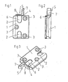
- FIG. 1 shows an example of a closing part 1 with two oppositely arranged recesses 2 for receiving locking pin.
- Such closing parts 1 are used in particular in connection with fittings, the actuating gear actuates two mutually oppositely arranged drive rods in opposite directions, so that two locking pins can be moved in opposite directions into these recesses 2 for locking.
- such closing parts 1 are designed for receiving mushroom-shaped safety pins.
- the closure member 1 is provided with a plurality of mounting holes 3, to ensure a stable frame-side screwing.
- an adapter part 5 is inserted by clamping, via an insert foot 6, to which a L-shaped in the present case functional projection 7 is formed.
- a contact surface 4 of the closing part 1 When completely wrapped adapter part 5 of the transition region between the insert foot 6 and functional projection 7 abuts against a contact surface 4 of the closing part 1 and thus assumes the desired position.
- the functional attachment 7 is designed L-shaped. This form of design is suitable, for example, for reshaping the closing part 1, which is initially suitable only in conjunction with a lock by means of safety mushroom pins, into a modified closing part 1, which makes it possible to lock by means of normal, cylindrical locking pins.
- FIG. 2 illustrates that, due to the adapter part 5 coupled to the closing part 1, the overall arrangement obtained remains within the height contour predetermined by the closing part 1, i. there can be no space problems.
- the perspective view of Fig. 3 can recognize the formation of the recess 2 as an undercut guide channel, and to this cross-sectional shape of the recess 2 of the insert 6 of the adapter part 5 is adjusted accordingly. Accordingly, the adapter part 5 can be easily pushed into this recess and then fixed with sufficient strength, for example, by a simple stroke.
- V-shape or W-shape in the foot area 8 of the adapter part 5 or their combination is mainly used when an interaction with a catch should be made with an elastic support member.
- the originally suitable only as a closing member 1 element is easily converted into a fitting part of fundamentally different function, ie it is then by the combination of closing part 1 and adapter part 5 in the same way as the original closing part 1 to be fastened new Functional component before, without such a functional component, which is required less frequently in practice than the closing part 1, even in storage would have to be kept.
Landscapes
- Engineering & Computer Science (AREA)
- Mechanical Engineering (AREA)
- Lock And Its Accessories (AREA)
- Closing And Opening Devices For Wings, And Checks For Wings (AREA)
- Window Of Vehicle (AREA)
- Crushing And Pulverization Processes (AREA)
- Food-Manufacturing Devices (AREA)
- Seal Device For Vehicle (AREA)
- Respiratory Apparatuses And Protective Means (AREA)
- Professional, Industrial, Or Sporting Protective Garments (AREA)
Description
- Die Erfindung betrifft einen Beschlag für Flügel von Fenstern, Türen und dergleichen mit an Stulpschienen geführten und über ein Betätigungsgetriebe in ihrer Längsrichtung verstellbaren Treibstangen, an denen mit rahmenfesten Schließteilen zusammenwirkende Riegelelemente vorgesehen sind. Zudem betrifft die vorliegende Erfindung eine Kombination aus einem Schließteil und einem Adapterteil zur Verwendung in derartigen Beschlägen.
- Bei derartigen Beschlägen ist es bereits bekannt, auf einer Stulpschiene im mittelbaren Bereich eines Schließzapfens ein Flachteil schwenkbeweglich anzuordnen, wobei je nach Beschlagkonzeption mit diesem Flachteil beispielsweise eine Schaltsperre bzw. eine Blockade des Schaltweges des Beschlages erzielt werden kann.
- Beschläge der erörterten Art müssen in der Praxis häufig an spezielle Anforderungen angepasst werden, um in einem Fall gewünschte und im anderen Fall nicht benötigte Funktionen realisieren zu können. Dies führt dazu, dass beim Beschlägehersteller wie auch beim Beschlägeverarbeiter stets eine entsprechend große Anzahl unterschiedlicher, zur Realisierung verschiedener Funktionen benötigter Beschlagteile auf Lager gehalten werden muss, was insbesondere zu einer störenden Erhöhung der Lagerhaltungskosten führt.
- Die DE 11 85 948 B offenbart eine Verriegelungseinrichtung mit einem rahmenfesten Schließblech mit einem auswechselbaren zungenartigen Glied, gegen das sich ein Schließzapfen beim Schließen anlehnt. Die verschiedenen zungenartigen Glieder unterscheiden sich in ihren Abmessungen, wodurch ein Verziehen der Tür-/oder Fensterflügel oder sonstige veränderte Passverhältnisse korrigiert werden können.
- Die CH 559 302 A offenbart einen Mittelverschluss für Schwenk-KippFlügel von Fenstern oder Türen mit einem an einer Treibstange angebrachten Verschlussglied und einem am feststehenden Rahmen angeschlagenen Schließstück. Das Schließstück kann aus einem Schließstückrahmen und einem in diesen einsetzbaren Steg zusammengesetzt sein. Dieser Steg ist so geformt, dass, je nachdem wie er eingesetzt wird, verschiedene Anschlagstellungen ermöglicht werden.
- Aus der DE 295 12 852 U1 ist eine Schubriegeleingriffsplatte für einen Fenster- oder Türverschluss mit einer für den Schubriegel vorgesehenen Eingriffsöffnung bekannt, deren Öffnungsweite mit Hilfe eines in zwei verschiedenen Positionen montierbaren Einsatzstückes verändert werden kann.
- Aufgabe der Erfindung ist es, für einen ein Verschlussgetriebe aufweisenden Beschlag der eingangs angegebenen Art und insbesondere für Verschlussgetriebe mit gegenläufig geführten Treibstangen und damit erzielbaren Doppelverriegelungen eine Möglichkeit zu schaffen, sowohl normale Verschlusszapfen als auch pilzförmige Sicherheitszapfen einzusetzen und ggf. noch zusätzliche Funktionen zu realisieren, ohne dass dazu jeweils individuell angepasste, Schließteile ggf. Einzelteile verwendet werden müssten.
- Gelöst wird diese Aufgabe nach der Erfindung durch eine Kombination aus einem Schließteil und einem Adapterteil nach Anspruch 1 und durch einen Beschlag nach Anspruch 9.
- Durch die erfindungsgemäße Kombination aus Schließteil und Adapterteil wird es möglich, die sonst üblicherweise im Lager vorzuhaltenden Einzel-Beschlagteile in ihrer Anzahl zu verringern, da durch die Kombination von generell vorhandenen Standard-Schließteilen mit speziellen Adapterteilen auf einfache und unkomplizierte Weise kombinierte, voll funktionstüchtige Beschlagteile entstehen, die Funktionen erfüllen können, welche von den Grund-Schließteilen nicht erfüllt werden konnten. So ist beispielsweise eine problemlose Anpassung der Schließteile an die Verwendung normaler Verschlusszapfen wie auch an die Verwendung pilzförmiger Sicherheitszapfen möglich, und es können über den jeweils ausgewählten Adaptern auch Gegenlager für beispielsweise einen Flügelheber, einen Schnäpper oder dergleichen geschaffen werden.
- Erfindungsgemäß ist jedes Adapterteil mit einem Einsatzfuß versehen, der form- und/oder Kraftschlüsig in eine Ausnehmung des Schließteils einbringbar ist und so dimensioniert ist, dass er vorzugsweise durch Klemmung in dieser Ausnehmung sicher fixierbar ist. Dabei sind keine ungewöhnlich großen Fixierungskräfte erforderlich, da in der Praxis das jeweilige Adapterteil zumindest im wesentlichen nicht in Auszugsrichtung wirkenden Kräften ausgesetzt ist.
- Der jeweils an den Einsatzfuß angeformte Funktionsansatz kann L-förmig, V-förmig, W-förmig oder in Form von Kombinationen dieser Gestaltungen ausgebildet sein.
- Ein L-förmiger Ansatz wird im Regelfall dann verwendet, wenn ein Hintergreifen dieses Ansatzes durch einen normalen Verschlusszapfen gefordert wird, aber ein derartiger L-förmiger Ansatz kann auch als Gegenlager zur Anlage und Abstützung eines Flügelhebers Verwendung finden. V- oder W-förmig ausgebildete Funktionsansätze werden im Regelfall dann verwendet, wenn ein Zusammenspiel mit einem Schnäpper gefordert ist.
- Weitere vorteilhafte Ausgestaltungen der Erfindung sind in den Unteransprüchen angegeben.
- Ein Ausführungsbeispiel der Erfindung wird unter Bezugnahme auf die Zeichnung erläutert; in dieser zeigt:
- Fig. 1
- eine Draufsicht einer Kombination von Schließteil und Adapterteil,
- Fig. 2
- eine Seitenansicht des Kombinationsteils nach Fig. 1, und
- Fig. 3
- eine perspektivische Darstellung des Kombinationsteils nach Fig. 1.
- Die Draufsicht nach Fig. 1 zeigt ein Beispiel eines Schließteils 1 mit zwei einander gegenüberliegend angeordneten Ausnehmungen 2 zur Aufnahme von Riegelzapfen. Derartige Schließteile 1 werden insbesondere im Zusammenhang mit Beschlägen verwendet, deren Betätigungsgetriebe zwei zueinanderliegend angeordnete Treibstangen gegenläufig betätigt, so dass zur Verriegelung zwei Riegelzapfen gegenläufig in diese Ausnehmungen 2 eingefahren werden können. Bevorzugt sind solche Schließteile 1 zur Aufnahme von pilzförmigen Sicherheitszapfen ausgebildet.
- Das Schließteil 1 ist mit mehreren Befestigungsöffnungen 3 versehen, um ein stabiles rahmenseitiges Verschrauben zu gewährleisten.
- In die obere der beiden Ausnehmungen 2 ist ein Adapterteil 5 klemmend eingebracht, und zwar über einen Einsatzfuß 6, an den ein im vorliegenden Fall L-förmig ausgebildeter Funktionsansatz 7 angeformt ist. Bei vollständig eingeschlagenem Adapterteil 5 liegt der Übergangsbereich zwischen Einsatzfuß 6 und Funktionsansatz 7 an einer Anlagefläche 4 des Schließteils 1 an und nimmt somit die Sollposition ein.
- Im dargestellten Ausführungsbeispiel ist der Funktionsansatz 7 L-förmig gestaltet. Diese Gestaltungsform eignet sich beispielsweise dazu, das zunächst nur im Zusammenhang mit einer Verriegelung mittels Sicherheits-Pilzzapfen geeignete Schließteil 1 in ein modifiziertes Schließteil 1 umzuformen, das eine Verriegelung mittels normaler, zylindrischer Verschlusszapfen ermöglicht.
- Die Seitenansicht nach Fig. 2 verdeutlicht, dass durch das mit dem Schließteil 1 gekoppelte Adapterteil 5 die erhaltene Gesamtanordnung innerhalb der durch das Schließteil 1 vorgegebenen Höhenkontur bleibt, d.h. es können keinerlei Raumprobleme entstehen.
- Die perspektivische Darstellung nach Fig. 3 lässt die Ausbildung der Ausnehmung 2 als hinterschnittenen Führungskanal erkennen, und an diese Querschnittsform der Ausnehmung 2 ist der Einsatzfuß 6 des Adapterteils 5 entsprechend angepasst. Das Adapterteil 5 lässt sich demgemäß einfach in diese Ausnehmung schieben und dann beispielsweise durch einen einfachen Schlag mit ausreichender Festigkeit fixieren.
- Durch die symmetrische Ausgestaltung des Adapterteils 5 kann eine Verwendung rechts und links erfolgen.
- Die in der Zeichnung nicht dargestellte V-Form oder W-Form im Fußbereich 8 des Adapterteils 5 oder deren Kombination wird vor allem dann verwendet, wenn ein Zusammenspiel mit einem Schnäpper mit einem elastischen Halteglied erfolgen soll. Für diesen Fall wird somit das ursprünglich nur als Schließteil geeignete Element 1 auf einfache Weise umgeformt in ein Beschlagteil von grundsätzlich anderer Funktion, d.h. es liegt dann durch die Kombination von Schließteil 1 und Adapterteil 5 ein in gleicher Weise wie das ursprüngliche Schließteil 1 zu befestigendes neues Funktionsbauteil vor, ohne dass ein solches Funktionsbauteil, das in der Praxis weniger häufig benötigt wird als das Schließteil 1, selbst auf Lager gehalten werden müsste.
-
- 1
- Schließteil
- 2
- Ausnehmung
- 3
- Befestigungsöffnung.
- 4
- Anlagefläche
- 5
- Adapterteil
- 6
- Einsatzfuß
- 7
- Funktionsansatz
- 8
- Fußbereich
Claims (9)
- Kombination aus Schließteil (1) und Adapterteil (5) zur Verwendung in ein Verschlussgetriebe aufweisenden Beschlägen für Fenster, Türen und dergleichen, die mit rahmenfesten Schließteilen zusammenwirkende Riegelelemente aufweisen, wobei
das Schließteil (1) durch form- und/ oder kraftschlüssige Verbindung mit wenigstens einem Adapterteil (5) zu einem Multifunktionsteil umrüstbar ist, wobei das Schließteil (1) eine Ausnehmung (2) für Riegelelemente aufweist, in die ein an dem Adapterteil (5) vorgesehener Einsatzfuß (6) einbringbar ist. - Kombination nach Anspruch 1,
dadurch gekennzeichnet,
dass das Schließteil (1) eine weitere Ausnehmung (2) zum Aufnehmen des Einsatzfußes (6) aufweist. - Kombination nach Anspruch 1 oder 2,
dadurch gekennzeichnet,
dass der Einsatzfuß (6) in der Ausnehmung (2) unter Klemmwirkung gehaltert ist. - Kombination nach einem der vorstehenden Ansprüche,
dadurch gekennzeichnet,
dass an den Einsatzfuß (6) jeweils ein Fußbereich (8) und ein Funktionsansatz (7) angeformt sind. - Kombination nach Anspruch 4,
dadurch gekennzeichnet,
dass der Funktionsansatz (7) L-förmig ausgebildet und insbesondere zum Zusammenwirken mit einem zumindest im wesentlichen zylindrischen Verschlusszapfen oder als Gegenlager zur Abstützung eines Flügelhebers bestimmt ist. - Kombination nach Anspruch 4,
dadurch gekennzeichnet,
dass der Fußbereich (8) V- oder W-förmig ausgebildet ist und insbesondere zur Aufnahme eines elastischen Rastglieds, z.B. eines Schnäppers, bestimmt ist. - Kombination nach Anspruch 4 und 5,
dadurch gekennzeichnet,
dass im Fußbereich (8) eine Kombination von L-Form, V-Form und/oder W-Form realisiert ist. - Kombination nach einem oder mehreren der vorhergehenden Ansprüche,
dadurch gekennzeichnet,
dass das Adapterteil (5) zur Ermöglichung einer Rechts-Links-Verwendung symmetrisch ausgebildet ist. - Beschlag für Flügel von Fenstern, Türen oder dergleichen mit an Stulpschienen geführten und über ein Betätigungsgetriebe in ihrer Längsrichtung verstellbaren Treibstangen, an denen mit rahmenfesten Schließteilen (1) zusammenwirkende Riegelelemente vorgesehen sind,
dadurch gekennzeichnet,
dass die Schließteile (1) gemeinsam mit Adapterteilen (5) eine Kombination nach einem der vorstehenden Ansprüche bilden.
Priority Applications (1)
| Application Number | Priority Date | Filing Date | Title |
|---|---|---|---|
| SI200330786T SI1396598T1 (sl) | 2002-09-03 | 2003-07-28 | Adapter za zapiralni del |
Applications Claiming Priority (2)
| Application Number | Priority Date | Filing Date | Title |
|---|---|---|---|
| DE20213561U | 2002-09-03 | ||
| DE20213561U DE20213561U1 (de) | 2002-09-03 | 2002-09-03 | Schließteil-Adapter |
Publications (2)
| Publication Number | Publication Date |
|---|---|
| EP1396598A1 EP1396598A1 (de) | 2004-03-10 |
| EP1396598B1 true EP1396598B1 (de) | 2007-02-21 |
Family
ID=30469905
Family Applications (1)
| Application Number | Title | Priority Date | Filing Date |
|---|---|---|---|
| EP03017088A Expired - Lifetime EP1396598B1 (de) | 2002-09-03 | 2003-07-28 | Schliessteil-Adapter |
Country Status (4)
| Country | Link |
|---|---|
| EP (1) | EP1396598B1 (de) |
| AT (1) | ATE354713T1 (de) |
| DE (2) | DE20213561U1 (de) |
| SI (1) | SI1396598T1 (de) |
Family Cites Families (4)
| Publication number | Priority date | Publication date | Assignee | Title |
|---|---|---|---|---|
| DE1185948B (de) * | 1958-09-23 | 1965-01-21 | Curt Weinert | Verriegelungseinrichtung fuer Fenster, Tueren od. dgl. |
| CH559302A5 (de) * | 1972-06-09 | 1975-02-28 | Bilstein August Fa | |
| GB8706436D0 (en) * | 1987-03-18 | 1987-04-23 | Scholes E M H | Keeper for retaining door/window |
| DE29512852U1 (de) * | 1995-08-10 | 1995-10-26 | Siegenia-Frank Kg, 57074 Siegen | Schubriegel-Eingriffsplatte für Fenster- und Türverschlüsse |
-
2002
- 2002-09-03 DE DE20213561U patent/DE20213561U1/de not_active Expired - Lifetime
-
2003
- 2003-07-28 EP EP03017088A patent/EP1396598B1/de not_active Expired - Lifetime
- 2003-07-28 SI SI200330786T patent/SI1396598T1/sl unknown
- 2003-07-28 AT AT03017088T patent/ATE354713T1/de active
- 2003-07-28 DE DE50306567T patent/DE50306567D1/de not_active Expired - Lifetime
Also Published As
| Publication number | Publication date |
|---|---|
| DE20213561U1 (de) | 2004-01-15 |
| SI1396598T1 (sl) | 2007-08-31 |
| ATE354713T1 (de) | 2007-03-15 |
| EP1396598A1 (de) | 2004-03-10 |
| DE50306567D1 (de) | 2007-04-05 |
Similar Documents
| Publication | Publication Date | Title |
|---|---|---|
| EP3266969B1 (de) | Eckumlenkung eines beschlages für einen flügel eines fensters oder einer tür | |
| DE69805903T2 (de) | Beschlag mit einstellbarem Riegel für Schiebeflügel | |
| EP2113624B1 (de) | Tür- oder Fenstersicherungsvorrichtung | |
| EP0556442B1 (de) | Treibstangenbeschlag für Fenster, Türen od. dgl. | |
| DE29620246U1 (de) | Band für Türen oder Fenster | |
| EP1678402B1 (de) | Vorrichtung zur aufnahme des gewichtes einer ein- oder zweiflügeligen tür für einen schaltschrank | |
| EP0761920B2 (de) | Fenster/Tür mit Dreh-Kipp-Beschlag | |
| EP0733761B1 (de) | Flügelrahmen | |
| EP1746235B1 (de) | Beschlaganordnung | |
| EP0795669B1 (de) | Kantriegelbeschlag für den Standflügel einer doppelflügeligen Tür | |
| DE1964842A1 (de) | Beschlag fuer Fenster,Tueren u.dgl. | |
| EP1425489B1 (de) | Drehkippbeschlag | |
| DE29600891U1 (de) | Sicherungseinrichtung | |
| EP1396598A1 (de) | Schliessteil-Adapter | |
| EP0913546B1 (de) | Getriebebeschlag für einen Flügelrahmen | |
| DE29815095U1 (de) | Niveauschaltsperre | |
| DE2805465A1 (de) | Beschlagsbaugruppe fuer fenster, tueren o.dgl. | |
| EP0748913B1 (de) | Funktionselement | |
| DE29901473U1 (de) | Bandseitensicherung für Tür- oder Fensterflügel | |
| EP4375463A1 (de) | Beschlagsteil | |
| DE29512995U1 (de) | Anschlagvorrichtung für Türen oder Tore | |
| EP0672811A1 (de) | Fehlbedienungssperre für das Betätigungsgestänge eines Fensters, einer Tür od. dgl. | |
| DE202007011394U1 (de) | Fenster oder Tür und Bauteilsatz eines Riegelteils für ein Fenster oder eine Tür | |
| DE29602615U1 (de) | Vorrichtung zur Sicherung eines zwischen zwei Endstellungen bewegbaren Bauteils zum Verschließen einer Wandöffnung eines Gebäudes | |
| DE29715560U1 (de) | Schwenkhebelverschlußvorrichtung |
Legal Events
| Date | Code | Title | Description |
|---|---|---|---|
| PUAI | Public reference made under article 153(3) epc to a published international application that has entered the european phase |
Free format text: ORIGINAL CODE: 0009012 |
|
| AK | Designated contracting states |
Kind code of ref document: A1 Designated state(s): AT BE BG CH CY CZ DE DK EE ES FI FR GB GR HU IE IT LI LU MC NL PT RO SE SI SK TR |
|
| AX | Request for extension of the european patent |
Extension state: AL LT LV MK |
|
| 17P | Request for examination filed |
Effective date: 20040415 |
|
| 17Q | First examination report despatched |
Effective date: 20041018 |
|
| AKX | Designation fees paid |
Designated state(s): AT BE BG CH CY CZ DE DK EE ES FI FR GB GR HU IE IT LI LU MC NL PT RO SE SI SK TR |
|
| GRAP | Despatch of communication of intention to grant a patent |
Free format text: ORIGINAL CODE: EPIDOSNIGR1 |
|
| GRAS | Grant fee paid |
Free format text: ORIGINAL CODE: EPIDOSNIGR3 |
|
| GRAA | (expected) grant |
Free format text: ORIGINAL CODE: 0009210 |
|
| AK | Designated contracting states |
Kind code of ref document: B1 Designated state(s): AT BE BG CH CY CZ DE DK EE ES FI FR GB GR HU IE IT LI LU MC NL PT RO SE SI SK TR |
|
| PG25 | Lapsed in a contracting state [announced via postgrant information from national office to epo] |
Ref country code: FI Free format text: LAPSE BECAUSE OF FAILURE TO SUBMIT A TRANSLATION OF THE DESCRIPTION OR TO PAY THE FEE WITHIN THE PRESCRIBED TIME-LIMIT Effective date: 20070221 Ref country code: IE Free format text: LAPSE BECAUSE OF FAILURE TO SUBMIT A TRANSLATION OF THE DESCRIPTION OR TO PAY THE FEE WITHIN THE PRESCRIBED TIME-LIMIT Effective date: 20070221 Ref country code: DK Free format text: LAPSE BECAUSE OF FAILURE TO SUBMIT A TRANSLATION OF THE DESCRIPTION OR TO PAY THE FEE WITHIN THE PRESCRIBED TIME-LIMIT Effective date: 20070221 |
|
| REG | Reference to a national code |
Ref country code: GB Ref legal event code: FG4D Free format text: NOT ENGLISH |
|
| REG | Reference to a national code |
Ref country code: CH Ref legal event code: EP |
|
| REF | Corresponds to: |
Ref document number: 50306567 Country of ref document: DE Date of ref document: 20070405 Kind code of ref document: P |
|
| REG | Reference to a national code |
Ref country code: IE Ref legal event code: FG4D Free format text: LANGUAGE OF EP DOCUMENT: GERMAN |
|
| PG25 | Lapsed in a contracting state [announced via postgrant information from national office to epo] |
Ref country code: SE Free format text: LAPSE BECAUSE OF FAILURE TO SUBMIT A TRANSLATION OF THE DESCRIPTION OR TO PAY THE FEE WITHIN THE PRESCRIBED TIME-LIMIT Effective date: 20070521 |
|
| PG25 | Lapsed in a contracting state [announced via postgrant information from national office to epo] |
Ref country code: BG Free format text: LAPSE BECAUSE OF EXPIRATION OF PROTECTION Effective date: 20070522 |
|
| PG25 | Lapsed in a contracting state [announced via postgrant information from national office to epo] |
Ref country code: ES Free format text: LAPSE BECAUSE OF FAILURE TO SUBMIT A TRANSLATION OF THE DESCRIPTION OR TO PAY THE FEE WITHIN THE PRESCRIBED TIME-LIMIT Effective date: 20070601 |
|
| PG25 | Lapsed in a contracting state [announced via postgrant information from national office to epo] |
Ref country code: PT Free format text: LAPSE BECAUSE OF FAILURE TO SUBMIT A TRANSLATION OF THE DESCRIPTION OR TO PAY THE FEE WITHIN THE PRESCRIBED TIME-LIMIT Effective date: 20070723 |
|
| ET | Fr: translation filed | ||
| GBV | Gb: ep patent (uk) treated as always having been void in accordance with gb section 77(7)/1977 [no translation filed] |
Effective date: 20070221 |
|
| REG | Reference to a national code |
Ref country code: IE Ref legal event code: FD4D |
|
| PG25 | Lapsed in a contracting state [announced via postgrant information from national office to epo] |
Ref country code: GB Free format text: LAPSE BECAUSE OF FAILURE TO SUBMIT A TRANSLATION OF THE DESCRIPTION OR TO PAY THE FEE WITHIN THE PRESCRIBED TIME-LIMIT Effective date: 20070221 |
|
| PLBE | No opposition filed within time limit |
Free format text: ORIGINAL CODE: 0009261 |
|
| STAA | Information on the status of an ep patent application or granted ep patent |
Free format text: STATUS: NO OPPOSITION FILED WITHIN TIME LIMIT |
|
| PG25 | Lapsed in a contracting state [announced via postgrant information from national office to epo] |
Ref country code: RO Free format text: LAPSE BECAUSE OF FAILURE TO SUBMIT A TRANSLATION OF THE DESCRIPTION OR TO PAY THE FEE WITHIN THE PRESCRIBED TIME-LIMIT Effective date: 20070221 |
|
| 26N | No opposition filed |
Effective date: 20071122 |
|
| REG | Reference to a national code |
Ref country code: CH Ref legal event code: PL |
|
| PG25 | Lapsed in a contracting state [announced via postgrant information from national office to epo] |
Ref country code: MC Free format text: LAPSE BECAUSE OF NON-PAYMENT OF DUE FEES Effective date: 20070731 Ref country code: LI Free format text: LAPSE BECAUSE OF NON-PAYMENT OF DUE FEES Effective date: 20070731 Ref country code: CH Free format text: LAPSE BECAUSE OF NON-PAYMENT OF DUE FEES Effective date: 20070731 Ref country code: GR Free format text: LAPSE BECAUSE OF FAILURE TO SUBMIT A TRANSLATION OF THE DESCRIPTION OR TO PAY THE FEE WITHIN THE PRESCRIBED TIME-LIMIT Effective date: 20070522 |
|
| PG25 | Lapsed in a contracting state [announced via postgrant information from national office to epo] |
Ref country code: EE Free format text: LAPSE BECAUSE OF FAILURE TO SUBMIT A TRANSLATION OF THE DESCRIPTION OR TO PAY THE FEE WITHIN THE PRESCRIBED TIME-LIMIT Effective date: 20070221 |
|
| PG25 | Lapsed in a contracting state [announced via postgrant information from national office to epo] |
Ref country code: CY Free format text: LAPSE BECAUSE OF FAILURE TO SUBMIT A TRANSLATION OF THE DESCRIPTION OR TO PAY THE FEE WITHIN THE PRESCRIBED TIME-LIMIT Effective date: 20070221 |
|
| PG25 | Lapsed in a contracting state [announced via postgrant information from national office to epo] |
Ref country code: LU Free format text: LAPSE BECAUSE OF NON-PAYMENT OF DUE FEES Effective date: 20070728 |
|
| PG25 | Lapsed in a contracting state [announced via postgrant information from national office to epo] |
Ref country code: HU Free format text: LAPSE BECAUSE OF FAILURE TO SUBMIT A TRANSLATION OF THE DESCRIPTION OR TO PAY THE FEE WITHIN THE PRESCRIBED TIME-LIMIT Effective date: 20070822 Ref country code: TR Free format text: LAPSE BECAUSE OF FAILURE TO SUBMIT A TRANSLATION OF THE DESCRIPTION OR TO PAY THE FEE WITHIN THE PRESCRIBED TIME-LIMIT Effective date: 20070221 |
|
| PGFP | Annual fee paid to national office [announced via postgrant information from national office to epo] |
Ref country code: CZ Payment date: 20090723 Year of fee payment: 7 Ref country code: NL Payment date: 20090730 Year of fee payment: 7 |
|
| PGFP | Annual fee paid to national office [announced via postgrant information from national office to epo] |
Ref country code: BE Payment date: 20090713 Year of fee payment: 7 |
|
| BERE | Be: lapsed |
Owner name: MAYER & CO. Effective date: 20100731 |
|
| REG | Reference to a national code |
Ref country code: NL Ref legal event code: V1 Effective date: 20110201 |
|
| PG25 | Lapsed in a contracting state [announced via postgrant information from national office to epo] |
Ref country code: CZ Free format text: LAPSE BECAUSE OF NON-PAYMENT OF DUE FEES Effective date: 20100728 Ref country code: NL Free format text: LAPSE BECAUSE OF NON-PAYMENT OF DUE FEES Effective date: 20110201 |
|
| REG | Reference to a national code |
Ref country code: FR Ref legal event code: TP |
|
| PG25 | Lapsed in a contracting state [announced via postgrant information from national office to epo] |
Ref country code: BE Free format text: LAPSE BECAUSE OF NON-PAYMENT OF DUE FEES Effective date: 20100731 |
|
| REG | Reference to a national code |
Ref country code: SK Ref legal event code: TE4A Ref document number: E 1819 Country of ref document: SK Owner name: MACO VERMOEGENSVERWALTUNG GMBH, SALZBURG, AT Effective date: 20110603 Ref country code: SK Ref legal event code: PC4A Ref document number: E 1819 Country of ref document: SK Owner name: MACO VERMOEGENSVERWALTUNG GMBH, TRIEBEN, AT Free format text: FORMER OWNER: MAYER & CO., SALZBURG, AT Effective date: 20110603 |
|
| REG | Reference to a national code |
Ref country code: SI Ref legal event code: SP73 Owner name: MACO VERMOEGENSVERWALTUNG GMBH; AT Effective date: 20110905 |
|
| REG | Reference to a national code |
Ref country code: FR Ref legal event code: TP Owner name: MACO TECHNOLOGIE GMBH, AT Effective date: 20120207 |
|
| REG | Reference to a national code |
Ref country code: DE Ref legal event code: R081 Ref document number: 50306567 Country of ref document: DE Owner name: MACO TECHNOLOGIE GMBH, AT Free format text: FORMER OWNER: MACO VERMOEGENSVERWALTUNG GMBH, SALZBURG, AT Effective date: 20120126 Ref country code: DE Ref legal event code: R082 Ref document number: 50306567 Country of ref document: DE Representative=s name: MANITZ, FINSTERWALD & PARTNER GBR, DE Effective date: 20120126 Ref country code: DE Ref legal event code: R082 Ref document number: 50306567 Country of ref document: DE Representative=s name: MANITZ FINSTERWALD PATENTANWAELTE PARTMBB, DE Effective date: 20120126 |
|
| REG | Reference to a national code |
Ref country code: SI Ref legal event code: SP73 Owner name: MACO TECHNOLOGIE GMBH; AT Effective date: 20120524 |
|
| REG | Reference to a national code |
Ref country code: SK Ref legal event code: PC4A Ref document number: E 1819 Country of ref document: SK Owner name: MACO TECHNOLOGIE GMBH, SALZBURG, AT Free format text: FORMER OWNER: MACO VERMOEGENSVERWALTUNG GMBH, SALZBURG, AT Effective date: 20120403 |
|
| REG | Reference to a national code |
Ref country code: AT Ref legal event code: PC Ref document number: 354713 Country of ref document: AT Kind code of ref document: T Owner name: MACO TECHNOLOGIE GMBH, AT Effective date: 20121005 |
|
| REG | Reference to a national code |
Ref country code: FR Ref legal event code: PLFP Year of fee payment: 14 |
|
| REG | Reference to a national code |
Ref country code: FR Ref legal event code: PLFP Year of fee payment: 15 |
|
| REG | Reference to a national code |
Ref country code: FR Ref legal event code: PLFP Year of fee payment: 16 |
|
| PGFP | Annual fee paid to national office [announced via postgrant information from national office to epo] |
Ref country code: GB Payment date: 20180719 Year of fee payment: 17 |
|
| REG | Reference to a national code |
Ref country code: AT Ref legal event code: MM01 Ref document number: 354713 Country of ref document: AT Kind code of ref document: T Effective date: 20190728 |
|
| PG25 | Lapsed in a contracting state [announced via postgrant information from national office to epo] |
Ref country code: AT Free format text: LAPSE BECAUSE OF NON-PAYMENT OF DUE FEES Effective date: 20190728 |
|
| PGFP | Annual fee paid to national office [announced via postgrant information from national office to epo] |
Ref country code: SK Payment date: 20220721 Year of fee payment: 20 Ref country code: IT Payment date: 20220726 Year of fee payment: 20 Ref country code: DE Payment date: 20220720 Year of fee payment: 20 |
|
| PGFP | Annual fee paid to national office [announced via postgrant information from national office to epo] |
Ref country code: SI Payment date: 20220719 Year of fee payment: 20 Ref country code: FR Payment date: 20220720 Year of fee payment: 20 |
|
| REG | Reference to a national code |
Ref country code: DE Ref legal event code: R071 Ref document number: 50306567 Country of ref document: DE |
|
| REG | Reference to a national code |
Ref country code: SK Ref legal event code: MK4A Ref document number: E 1819 Country of ref document: SK Expiry date: 20230728 |
|
| PG25 | Lapsed in a contracting state [announced via postgrant information from national office to epo] |
Ref country code: SK Free format text: LAPSE BECAUSE OF EXPIRATION OF PROTECTION Effective date: 20230728 Ref country code: SI Free format text: LAPSE BECAUSE OF EXPIRATION OF PROTECTION Effective date: 20230729 |